The Capture, Compare, and PWM (CCP) modules are built-in modules in the PIC microcontrollers. These modules are designed for modulation, waveform generation, and time delay applications. They contain a 16-bit register that can operate as:
Capture Mode
If a register constantly changes its value, this mode provides access to the current state of that register. In this case, it is the timer TMR1 register.
Compare Mode
This mode constantly compares the values of two registers. One of those registers is the timer TMR1 register. When a predetermined amount of time expires, this circuit also allows the user to trigger an external event.
PWM (Pulse Width Modulation)
This mode can generate signals of varying frequency and duty cycle on one or more output pins.
CCP Module in PIC18F452 Microcontroller
PIC18F452 microcontroller contains built-in two CCP modules (CCP1 and CCP2). Both modules are identical in their operation except in the special event trigger operation. In this article, the CCP1 module is discussed in detail.
TIMER RESOURCES
The CCP module requires the use of a timer in combination with it to function. Each CCP module utilizes different timer resources for the capture, compare, and PWM modes. The timers needed by them are:
- Capture Timer1
- Compare Timer1
- PWM Timer2
CCP1 Module of PIC Microcontroller
The central part of this module’s circuit contains a 16-bit CCPR1 Register which consists of:
- 8-bit CCPR1L Register (low byte)
- 8-bit CCPR1H Register (high byte)
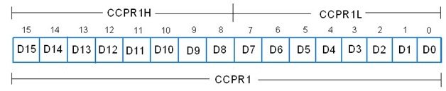
The timer register TMR1 uses this register to capture or compare binary numbers, or we can say that it loads a count in this register for comparison.
CCP1CON Register
The CCPCON register selects the modes of the CCP module by using its bits (CCPxM CCPxM0). It explains the selection of the CCP mode in the process of capture and compare modes.

CCP1 CAPTURE MODE:
In this mode, the CCPR1 register (CCPR1H and CCPR1L) copies the timer register TMR1, which consists of TMR1H and TMR1L. The transfer of 16-bit data is determined by the combination of the four bits (CCP1M3-CCP1M0) of the control register, indicating which events will cause the transfer.
| CCP1 Mode | CCP1CON Register Bits 3:0 |
|---|---|
| Capture mode, Every falling edge on RC2/CCP1 pin | 0100 |
| Capture mode, Every rising edge on CCP1 pin | 0101 |
| Capture mode, Every 4th rising edge on CCP1 pin | 0110 |
| Capture mode, Every 16th rising edge on CCP1 pin | 0111 |
Configure the RC2/CCP1 pin as an input pin and ensure that the TMR1 module operates as a timer or synchronous counter.
CCP1 COMPARE MODE:
In this mode, the microcontroller constantly compares the value stored in the 16-bit CCPR1 register with the value stored in the TMR1 or TMR3 register. If the value in the CCPR1 register matches the Timer value, it can change the logic state of the RC2/CCP1 output pin and generate the CCPIF (Interrupt Flag). The specific logic state depends on the configuration of bits in the control register (CCP1M3 – CCP1M0).
| CCP1 Mode | CCP1CON Register Bits 3:0 |
|---|---|
| Compare mode, Initialize CCP pin Low, on compare match force CCP pin High (CCPIF bit is set) | 1000 |
| Compare mode, Initialize CCP pin High, on compare match force CCP pin Low (CCPIF bit is set) | 1001 |
| Compare mode, Generate software interrupt on compare match, CCP pin is unaffected (CCPIF bit is set) | 1010 |
| Compare mode, Trigger special event (CCPIF bit is set) | 1011 |
To convert the sentence into active voice, we need to identify the subject performing the action. However, the given sentence does not contain an action or a subject. Could you please provide more context or a sentence with an action?
The Timer3 Control Register selects Timer1 or Timer3 for compare mode.
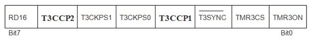
The T3CCP2:T3CCP1 bits are used to select the Timer for Compare mode operation.
- 00: Timer1 for both CCP modules
- 01: Timer1 for CCP1 module
- 10: Timer3 for CCP2 module
- 1x: Timer3 for both CCP modules
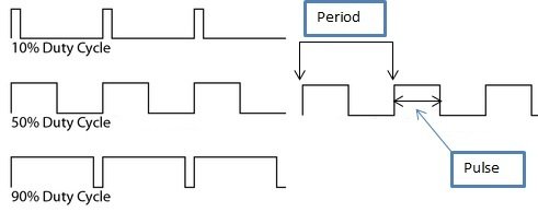
CCP1 PWM MODE:
The signals that have varied frequency and duty cycle have a wide range of applications in automation. Pulse width modulation (PWM) is a great technique for controlling analog circuits with microcontroller digital outputs. If the signal is high, that will indicate the on-time, and if it is low, that is the off-time. From this, we can determine the duty cycle.
Set PWM Period of CCP Module in PIC Microcontroller
The output pulse period (T) of the waveform is determined by the PR2 register of the timer TMR2. The PWM period can be calculated as:
PWM Period = TPWM = (PR2 + 1) * 4 * TOSC * TMR2 Prescale Value
- If FOSC is 20MHz
- TOSC = 1 / FOSC = 0.05 µs
- TMR2 prescaler value = 1
- If PR2 = 0xFFFF = 65535
PWM Period = TPWM = (65535 + 1) * 4 * 0.05µs * 1 = 13.1ms
FPWM = 1 / TPWM = 76KHz.
Set PWM Duty Cycle
The PWM duty cycle is specified by using a total of 10 bits:
- MSBs consist of eight bits of CCPR1L register
- LSBs consist of the 2 bits of CCP1CON register (DC1B1 and DC1B0)
Firstly, we have to write a 10-bit value (from 0 to 1023) to the CCPR1L register concatenated with CCP1CON<5:4> bits. The formula for calculation is:
Pulse Width = (CCPR1L, DC1B1, DC1B0) * Tosc * TMR2 Prescale Value
Since the duty cycle = value / [4 * (PR2 + 1)], if the program starts with a 50% duty cycle, TOSC = 0.05 µs, TMR2 prescale value = 1:
- duty cycle = value / [4 * (PR2 + 1)]
- value = duty cycle * [4 * (PR2 + 1)]
- value = (50 / 100) * [4 * (65535 + 1) = 131072
PWM Duty Cycle = (CCPR1L:CCP1CON<5:4>) * Tosc * Timer2 prescale value
= 131072 * 0.05 µs * 1 = 6.5ms
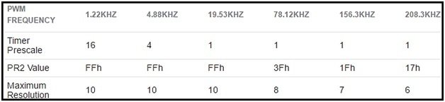
To get the desired PWM frequencies using Fosc = 20MHz, the Timer Prescaler, and PR2 values can be set as:
How to Generate PWM Using CCP Module of PIC Microcontroller
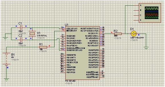
In this example, we will use the compare mode to generate a 50Hz output with a 50% duty cycle. A crystal oscillator of frequency 20MHz is used with PIC18F452. Pin RC2 is used as the output pin, and an oscilloscope is used to monitor the output wave.
CALCULATIONS:
- FOSC is 20 MHz
- TOSC = 1 / FOSC = 0.05 µs
- TMR2 prescale value = 1
- If PR2 = 0xFFFF = 65535
PWM Period = TPWM = (65535 + 1) * 4 * 0.05µs * 1 = 13 ms
FPWM = 1 / TPWM = 76KHz.
TMR1 increment takes 1 instruction cycle (with Prescaler 1:1), or we can say that TMR1 overflow takes 65536 instruction cycles. For 50Hz:
- Time period = TPWM = 20ms
- Tcy = (1 / 20MHz) * 4 = 0.2µs
- With a 50% duty cycle, on-time is 10ms
- The number of instruction cycles in 10ms = 10ms / 0.2 µs = 50000
This means that 10ms have elapsed when TMR1 counted from 0 to 50000. So what we do next is:
- Assign CCPR1 = 50000 = 0xC350.
- CCPR1H is set to 0xC3 and CCPR1L is set to 0x50.
- A compare match occurs every 10ms now.
- TMR1 is reset upon a compare match.
Program CCP Module
- Set the output pin as RC2.
- Set CCP1CON to 0x0B for our required mode of operation.
- Enable CCP1IE, GIE, and PEIE for interrupted usage.
- Toggle the state of RC2 in the interrupt service routine (ISR).
- Toggle the state of RC2 every 10ms.
Circuit Diagram

Generated WaveForm

MikroC Code
This code essentially generates a 50 Hz square wave with a 50% duty cycle on pin RC2 (Port C, Pin 2) output using the CCP1 module and Timer1 of the PIC18F452 microcontroller.
The code for this project is written in the MIKROC compiler. If you do not know how to use MikroC for Pic, you can refer to these tutorials:
- How to Use “MikroC PRO for PIC” to Program PIC Microcontrollers
- Pic microcontroller programming in c using Mikroc Pro for PIC
// PIC18F452 Configuration
// Crystal oscillator frequency: 20 MHz
// Internal oscillator frequency: 1 MHz
// Timer1 Prescaler: 1:1

void main() {
    PORTC = 0x00;      // Configure Port C as output
    TRISC = 0x00;      // Set all pins of Port C as output
    CCP1CON = 0x0B;    // Configure CCP1 module for Compare mode, Trigger special event (CCPIF bit is set)
    CCP1IE_bit = 1;    // Enable CCP1 interrupt
    GIE_bit = 1;       // Enable global interrupts
    PEIE_bit = 1;      // Enable peripheral interrupts

    // Set the compare value for CCP1 to generate a 50 Hz signal
    CCPR1H = 0xC3;     // High byte of counter value (CCPR1)
    CCPR1L = 0x50;     // Low byte of counter value (CCPR1)

    T1CON = 0x01;      // Timer1 configuration: Prescaler 1:1, Start Timer 1

    while (1) {
        // Any additional tasks you want to perform
    }
}

void interrupt() {
    if (CCP1IF_bit == 1) {   // Check if CCP1 interrupt flag is set
        RC2_bit = ~RC2_bit;  // Toggle RC2 (Port C, Pin 2) to generate the 50 Hz square wave
        CCP1IF_bit = 0;      // Clear CCP1 interrupt flag
    }
}
How does this Code Work?
Here’s an explanation of the code:
Configuration
The code sets up the necessary configuration for the PIC18F452 microcontroller. It configures Port C (RC) as an output and initializes the CCP1 module for Compare mode with a special event trigger. It enables the CCP1 interrupt, global interrupts (GIE), and peripheral interrupts (PEIE).
CCP1 Compare Value
The compare value (CCPR1) is set to generate a 50 Hz signal. The values 0xC350 are loaded into CCPR1H and CCPR1L. These values are calculated to create a 50 Hz waveform with a 50% duty cycle.
Timer1 Configuration
Timer1 (TMR1) configures with a prescaler of 1:1, and it starts to count.
Main Loop: The while (1) loop is the main program loop where you can perform additional tasks if needed.
Interrupt Service Routine
The interrupt service routine (ISR) executes the interrupt() function when the CCP1 interrupt flag (CCP1IF_bit) is set. It toggles Pin RC2 (Port C, Pin 2) to generate the square wave and clears the CCP1 interrupt flag.
Conclusion
In conclusion, the CCP module, which stands for Capture, Compare, and PWM, is a crucial component built into PIC microcontrollers. It offers various modes of operation, such as capturing the state of a register, comparing two register values, and generating signals with varying frequency and duty cycle. The CCP module, along with the associated timers, provides a versatile toolset for modulation, waveform generation, and time delay applications. Understanding the functionality and configuration of the CCP module allows developers to harness the power of PIC microcontrollers for a wide range of tasks. With its ability to capture, compare, and generate signals, the CCP module proves to be an essential feature that enhances the capabilities of PIC microcontrollers.
You may also like to read:
- Internal EEPROM of PIC Microcontroller (PIC18F452)
- SPI Communication with PIC microcontroller
- Use UART Interrupt of Pic Microcontroller with Examples (PIC18F4550)
- UART Communication with Pic Microcontroller( Programming in MPLAB XC8 )
- How to use DAC Module of Pic Microcontroller and Generate waveforms
- PIC Microcontroller ADC – How to Use PIC18F4550 ADC
- Pulse width measurement using pic microcontroller
how can you have value in pr2 more tha 255
how can i modify duty cycle from 10% to 20% ?
good effort thank you sir
Hello,
Do you have the source code in capture mode? I am having problem to read the pulse width using CCP mode of pic16f877a.