In this tutorial, we will learn to measure AC voltage using a pic microcontroller with two methods. One is using a potential transformer and the second one is using an op-amp as a difference amplifier. That means, in the first method, we will use a voltage transformer to step down 220V AC and in the second method, we will use an operational amplifier as a difference amplifier to step down high AC voltage. But for both methods, we will use pic microcontroller ADC to take AC voltage samples. For this tutorial, we will use the PIC16F877A microcontroller. However, the logic used in this tutorial can be used with other microcontrollers such as 8051, AVR, Arduino, Raspberry Pi, Beaglebone, etc.
You have come across many online tutorials on various websites about voltage measurement using different microcontrollers. But all these tutorials are about measurement of low DC voltage. In this project, you will learn how to measure high AC voltage using PIC16f877A micrcontroller.
In this tutorial, We will discuss ac voltage sensing with two methods:
- Using the difference amplifier method.
- Using the potential transformer method.
Alternating Voltage Measurement using Difference Amplifier Method and Pic Microcontroller
To measure 220V AC, it is necessary to step down the voltage as microcontrollers are unable to measure voltages greater than 5V. Applying a voltage higher than 5V to the analog input of a microcontroller can result in permanent damage. Thus, in order to protect the microcontroller, it is crucial to step down the 220V AC voltage to an AC voltage with a peak value lower than 5V. For instance, 220V AC represents the RMS voltage, with a corresponding peak value of 311 volts. Therefore, it is essential to reduce the high AC voltage to a level where its peak value does not exceed 5 volts.
There are two methods to step down 220 alternating voltage into low alternating voltage whose peak value should not be greater than 5 volts.
- Potential Transformer ( All Electrical Engineering students must know about P.T and its use)
- Difference amplifier ( We will discuss the difference amplifier method in this project.)
The Potential Transformer is capable of stepping down 220 Alternating current voltage. However, why would you want to spend more money when you can achieve this using inexpensive operational amplifiers and just a few resistors? The difference amplifier method proves to be more economical than using a Potential Transformer when stepping down voltages below 400 volts AC.
NOTE: Difference amplifier method is economical for voltage measurement less than 400 volt. Because above 400 volt, this method become expensive than potential Transformer. There are reasons behind it. I am not going to discuss reasons here.This method is suitable for final year students who want to measure Alternating voltage and current.
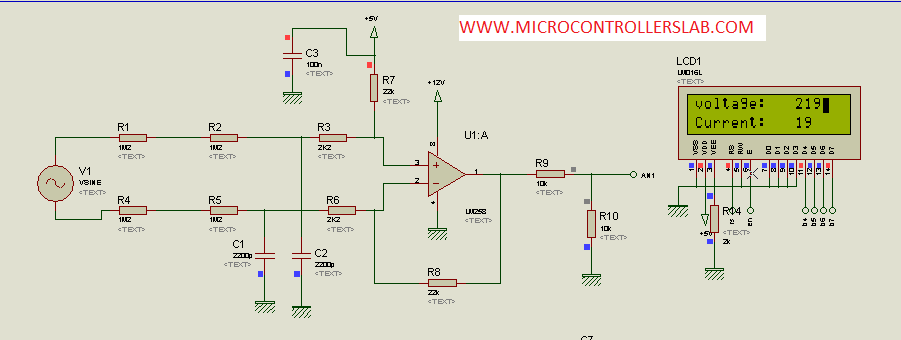
Difference Amplifier circuit
The difference amplifier is a circuit used to amplify voltage between two different voltage levels. When dealing with alternating voltage, there are two distinct voltage levels: one is positive relative to neutral, and the other is negative relative to neutral. For more detailed information on the difference amplifier and its applications, I would suggest conducting a search on Google.
You can adjust the gain of the difference amplifier according to your requirements by selecting the proper values of resistors. In this project, the gain is equal to:
Gain= R8/(R1+ R2+ R3) ;
In the case of alternating voltage, the second voltage level is zero. This is because during the positive and negative cycles, the other side is considered to be zero or neutral. As a result, the output voltage will be zero during these cycles.
vout = gain * Vinput;

In the above picture, resistors R1, R2, R3, R4, and R5 have high values, which prevent high voltage from appearing across the op-amp. The use of high input resistors ensures that the current is in the microampere range, resulting in low power loss in the milliwatt range. According to the difference amplifier gain formula, the gain can be calculated as follows:
gain= (22K)/( 1.2M + 1.2M + 2.2K) = 0.0091
NOTE: Please make sure to calculate the peak value of the sine wave, as the peak voltage is the maximum voltage input to the microcontroller’s analog pin. Therefore, with a gain of 0.0091 in respect to the peak voltage of the sine wave, the output voltage from the op-amp is:
Vout = .0091 * 311 = 2.8301 volt (peak output voltage)
In the figure above, we can observe that the other terminal of R7 is connected to the 5-volt supply instead of the ground, which is typically done when using a differential amplifier in various applications. The purpose of the R7 resistor is to raise the DC voltage level at the output of the op-amp. Since a sine wave has a zero DC voltage level and negative voltage cycle, it becomes important to increase the DC level of the sine wave by 5 volts. By doing so, we prevent any negative voltage from appearing across the microcontroller. Consequently, the output peak voltage from the op-amp becomes 5 volts plus 2.8301 volts, resulting in a total of 7.8301 volts. However, it is important to note that microcontrollers are unable to measure voltages greater than 5 volts. To address this, as illustrated in the figure above, a voltage divider is employed to divide the output voltage by 2. This ensures that the output voltage level is within the microcontroller’s measurement range.
Vout = 7.8301/2 = 3.90155;
Capacitors C1, C2, and C3 are used to filter harmonics from the input voltage and to provide protection to the microcontroller from harmonics. Now, the AN pin can be connected to the microcontroller analog pin to measure voltage easily.
Video lecture on AC voltmeter design
To know about how to measure analog voltage using the analog module of the PIC16F877A microcontroller, go through the PIC microcontrollers tutorials.
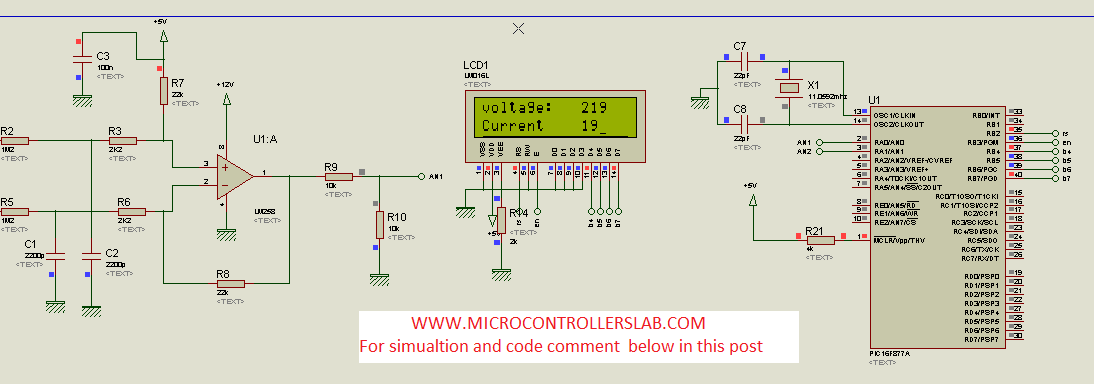
Circuit Diagram
To know about LCD interfacing with PIC microcontrollers, go through PIC microcontrollers tutorials.
Complete circuit diagram:
AC Voltage Measurement Code Pic Microcontroller
Code for this project is written using MikroC. To download code for AC voltage measurement click on the link below:
sbit LCD_RS at RB2_bit;
sbit LCD_EN at RB3_bit;
sbit LCD_D4 at RB4_bit;
sbit LCD_D5 at RB5_bit;
sbit LCD_D6 at RB6_bit;
sbit LCD_D7 at RB7_bit;
sbit LCD_RS_Direction at TRISB2_bit;
sbit LCD_EN_Direction at TRISB3_bit;
sbit LCD_D4_Direction at TRISB4_bit;
sbit LCD_D5_Direction at TRISB5_bit;
sbit LCD_D6_Direction at TRISB6_bit;
sbit LCD_D7_Direction at TRISB7_bit;
float v;
char txt[5];
char txt1[5];
void voltage_READ(void)
 {
 float max;
 int i;
 int t[40];
 ADCON0.ADON=1;
 for(i=0; i<=39; i++)
 {
 v= ADC_Read(0); //Digital value convert
 v =v*(10.0/1023.0);
 v=(v-5.0);
 t[i]=v*110.1909091;
 }

 ADCON0.ADON=0;
 max=t[0];
 for(i=0; i<=39; i++)
 {
 if(max<t[i])
 max=t[i];
 }
 max=max*.707106781;
 intToStr(max, txt);
 Lcd_out(1,9,txt);
 delay_ms(1000);
 }

void main()
{
 Lcd_Init(); // Initialize LCD
 ADCON0.ADCS1=1;
 ADCON0.ADCS1=0;
 ADCON0.ADON=0;

 while(1)
 {

 Lcd_out(1,1, "Voltage:");
 voltage_READ();
 }
}
AC Voltage Measurement using PT and Pic Microcontroller
In this section, we will see how to measure AC voltage using a potential transformer and Pic Microcontroller. In the last section, we have seen how to use an operational amplifier as a difference amplifier to step down AC voltage level from 220 volts AC to less than 5 volts AC. Here, we will delve further into the process of measuring AC voltage with the help of a potential transformer and a Pic Microcontroller. Understanding the intricacies and the practical applications of this setup is essential for accurate voltage measurements. By following the steps mentioned in the previous section, we can ensure that the AC voltage is accurately measured with the help of the potential transformer and Pic Microcontroller.
How to measure ac voltage?
Ac voltage can be measure with following methods:
- AC voltage measurement using digital millimeter
- AC voltage measurement using analog voltmeter
- AC voltage measurement using microcontroller
- AC voltage measurement using potential transformer and digital display (I will discuss this method in this tutorial)
- AC voltage measurement using difference amplifier and pic microcontroller
As I have already discussed in this project, I will be using potential transformer to step down 220volt ac voltage to less than 5 volt ac. I will discuss it later why we need to step down ac voltage to measure it with the help of pic microcontroller.
Components required
Followings are the main components of ac voltage measurement project. Brief descriptions of all components are also given below:
- Potential transformer
- Bridge rectifier
- voltage divider circuit
- Liquid crystal display
- PIC16F877A pic microcontroller
What is a potential transformer (PT)?
A potential transformer, also known as a voltage transformer, is a specific type of transformer that is used to decrease or “step down” the magnitude of AC voltage. Its primary purpose is to measure high voltage levels by transforming them into lower, more manageable values.
In this project, the potential transformer plays a crucial role in reducing the voltage from 220 volts AC to 12 volts AC. By utilizing a carefully calculated turns ratio, the secondary winding of the potential transformer consists of fewer turns than its primary winding, resulting in a significant decrease in voltage.
The turning ratio formula serves as a fundamental guideline for determining the appropriate number of winding turns, allowing the potential transformer to effectively step down the alternating current voltage and facilitate safe and accurate voltage measurement.
Ns/Np = Vs/VpWhat is bridge rectifier?
The bridge rectifier is an electronic circuit used to convert AC voltage into pulsating DC voltage. Essentially, it transforms the negative cycle of AC voltage into a positive cycle. So why do we need a bridge rectifier in this project? It’s because microcontrollers are unable to read negative voltage. Consequently, we must convert the negative half cycle of AC voltage into a positive cycle. The bridge rectifier is constructed by connecting rectifier diodes in a specific arrangement to form a bridge. For this purpose, we employ 1N4007 rectifier diodes to create an H Bridge.
Voltage Divider Circuit
The voltage divider circuit, as the name suggests, is used to divide voltage. It employs two resistors to achieve this. In this setup, a potential transformer steps down the 220V AC voltage to 12V AC. To convert the 12V AC into pulsating DC, a bridge rectifier is used. However, it is important to note that microcontrollers can only read voltages up to 5V. Therefore, the voltage divider circuit further divides the voltage into two parts, ensuring that less than 5V appears across the analog-to-digital converter pin of the PIC microcontroller. We will discuss the analog-to-digital converter in more detail later.
Liquid crystal display
Liquid crystal display or LCD is used to used to display value of measured ac voltage. 16X2 LCD is used in this project. LCD is interfaced with pic16f877a microcontroller. IF you don’t know how to interface LCD with PIC16F877A microcontroller, check following article:
PIC16F877A microcontroller
PIC16F877A microcontroller is used in this project. PIC16F877A microcontroller is belongs to 16F family of pic microcontrollers. It have built in analog to digital converters module. Some of basic features of PIC16F877A microcontroller is given below:
- Built in analog to digital converters
- Comparator modules
- Digital input and output pins
- Serial communication
- UART communication
- I2C communication and many others.
For more information about pic16f877a microcontroller features and if you are new to microcontroller’s worlds, check following article.
Circuit diagram of how to measure ac voltage using microcontroller
The circuit diagram for measuring AC voltage is presented below. In this section, we have discussed all the components of this project.
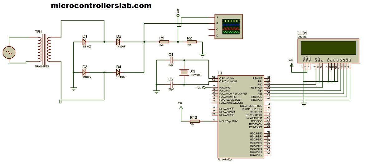
The input to the circuit is a 220-volt AC voltage. A potential transformer is used to step down the voltage from 220 volts AC to 12 volts AC. After that, a bridge rectifier converts the stepped-down AC voltage into pulsating DC voltage. A voltage divider is then used to further divide the voltage into two parts.
The voltage of less than 5 volts appears across the analog-to-digital converter pin of the PIC16F877A microcontroller. Microcontrollers are essentially small microcomputers that only understand digital values. The built-in analog-to-digital converter module of the PIC16F877A microcontroller converts the analog values of the AC voltage into digital values. These digital values are then used in processing the data within the microcontroller.
Instructions written in the form of code instruct the microcontroller on what to do. The microcontroller itself does not perform any tasks on its own. You need to provide it with instructions by writing a program that outlines what you want it to do.
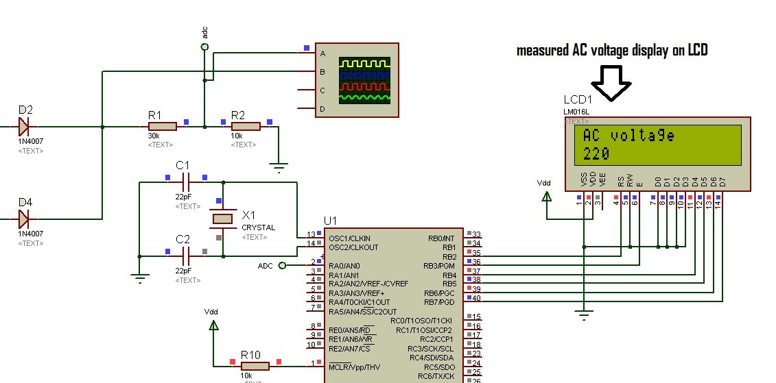
Proteus Simulation
The diagram below shows the simulation results of an AC voltage measurement project. The LCD displays a reading of 220 volts AC, which is measured using a microcontroller and the necessary components connected to it, including a potential transformer.
Code AC voltage Measurment using PT
The program given below is written using MikroC compiler.
// LCD module connections
sbit LCD_RS at RB2_bit;
sbit LCD_EN at RB3_bit;
sbit LCD_D4 at RB4_bit;
sbit LCD_D5 at RB5_bit;
sbit LCD_D6 at RB6_bit;
sbit LCD_D7 at RB7_bit;

sbit LCD_RS_Direction at TRISB2_bit;
sbit LCD_EN_Direction at TRISB3_bit;
sbit LCD_D4_Direction at TRISB4_bit;
sbit LCD_D5_Direction at TRISB5_bit;
sbit LCD_D6_Direction at TRISB6_bit;
sbit LCD_D7_Direction at TRISB7_bit;
// End LCD module connections

float maxpoint = 0;
int i;
unsigned int temp=0;

char ch[5];

void main()
{

TRISA = 0XFF;// All input
TRISB0_bit = 1;//set as input
TRISB1_bit = 1;//set as input
ADC_Init();

// Initialize LCD configuration...
Lcd_Init();
Lcd_Cmd(_LCD_CLEAR); // Clear display
Lcd_Cmd(_LCD_CURSOR_OFF); // Cursor off

while(1)

{
Lcd_Out(1,1,"AC voltage");

for(i=0;i<500;i++)
{
if(temp = ADC_Read(0),temp>maxpoint)
{
maxpoint = temp;
}
}
maxpoint = ( maxpoint * 5 )/ (1023) ;
maxpoint = maxpoint * 4;
maxpoint = maxpoint + 1.4;
maxpoint = maxpoint * 18;
maxpoint = maxpoint * ( 1 / sqrt(2) );
intToStr(maxpoint, ch);
lcd_out(2,1, Ltrim(ch));
maxpoint = 0;
}// while
}// void mai
These lines define the connections of the LCD module to the microcontroller’s pins. sbit stands for “single bit” and is used to specify the pin connections for the LCD control and data lines.
// LCD module connections
sbit LCD_RS at RB2_bit;
sbit LCD_EN at RB3_bit;
sbit LCD_D4 at RB4_bit;
sbit LCD_D5 at RB5_bit;
sbit LCD_D6 at RB6_bit;
sbit LCD_D7 at RB7_bit;
These lines define the direction of the LCD pins. TRISBx_bit are used to configure the corresponding pins as input (1) or output (0). These lines specify that RB2 (LCD_RS), RB3 (LCD_EN), RB4 (LCD_D4), RB5 (LCD_D5), RB6 (LCD_D6), and RB7 (LCD_D7) are configured as outputs, so they will be used to control the LCD.
sbit LCD_RS_Direction at TRISB2_bit;
sbit LCD_EN_Direction at TRISB3_bit;
sbit LCD_D4_Direction at TRISB4_bit;
sbit LCD_D5_Direction at TRISB5_bit;
sbit LCD_D6_Direction at TRISB6_bit;
sbit LCD_D7_Direction at TRISB7_bit;
These lines declare some variables used in the main function. maxpoint is a floating-point variable to store the maximum voltage value measured. i is an integer variable used as a loop counter. temp is an unsigned integer variable used to store the ADC reading. ch is an array of characters used to store the string representation of the voltage value.
float maxpoint = 0;
int i;
unsigned int temp = 0;
char ch[5];
In the main function, after initializing the LCD, it enters an infinite loop (while(1)). The loop does the following:
- Displays “AC voltage” on the first line of the LCD using Lcd_Out.
- It then starts a for loop that runs 500 times (from i = 0 to i < 500).
- Inside the loop, it reads an analog voltage value from channel 0 of the ADC using ADC_Read(0) and stores it in the variable temp.
- It then compares temp with the current maxpoint value, and if temp is greater, it updates maxpoint with the new value. This is done to find the maximum voltage value among the 500 readings.
- After the loop, it processes the maxpoint value to convert it into an AC voltage value. The exact formula used for conversion is defined above.
- The converted voltage value is then converted into a string using intToStr and stored in the ch array.
- The voltage value is displayed on the second line of the LCD using lcd_out.
In summary, in this tutorial, we have learned how to measure AC voltage using two different methods and a PIC microcontroller.
You may also like to read:
Hi,
can you send me its code and simulation file……………?
thanks ,
id: tahirnaeem90@hotmail.com
Hi,
can you send me its code and simulation file……………?
thanks ,
jone-1992@hotmail.com
Hello can you help me for the code.
Thanks in advanced.
hi bro please send me code for this AC voltmeter and ammeter projects
Thank you
Nice post.
Send schematic and code on prashantyerande@gmail.com
hello , iam idreesmuhamed , in the fact , your project is very important because iam electric engineer
, please send to me the code and iam be thankfull for you .
Dear i am new here on your blog.Can you please send me the code of this alternating voltage measurement project.
code downloading link is available at the end of post
cannot dowload the code bro
The information provided on your page here turns very useful for me and i thanks you for this.
I have made the simulation but having a little problem with the code so if you send me the code then i am very grateful to you.
I am an electrical engineering student in Delhi Technological University and the topic here on this page is similar to my minor topic so please help me and send the code as soon as possible.
I have added code downloadable link at the end of post. use this link to download code. Good luck
Please I need to measure three phase voltage line to line and three. Phase current by using pic18f4550
bro send the simulation and code
good tutorial can u send me the simulation
Use pictures given in article to draw circuit diagram
Dear Bilal,
Good work keep going, send me the source code in .c file if possible.
Pls try to elaborate on your ADC conversion using differential amplifier
Pls try to elaborate on your ADC conversion using differential amplifier in the software… Thanks
hi! can you explain me how to find the formular “for” look of source code:
v=v*(10.0/1023.0);
v=(v-5);
t[i]=v*110.1909091;
thanks you so much!
Hi please send for me the code
thanks so much!
Hello
Can you sent me the simulation file to wilsonabysj123@gmail.com
thank u so much Mr.bilal
can i follow ur website?
nice work
think you
kindly send me code at
ateebakmal1@gmail.com
Nice work! you have shown a easy way to interface and measure high voltage using microcontroller. Thank you. but I am having some doubts, after calculating current through resistors, it is 9.57×10^-5 so by calculating voltage drop across R1, so (9.57×10^-5) x(2.2M) is 219.34V it should be low isn’t it? please guide me.
Thank you for sharing with us! I have assembled this ckt on bread board, without interfacing it with PIC. So the output voltage should be 7V DC(without voltage dividing) isn’t it? but mine is getting 5V DC so what might be the problem? or its normal ?
check your circuit connections and its also depend on maximum input voltage to difference amplifier
If you are using a multimeter to measure the o/p voltage it shows the average voltage . use dso instead.
Hi, will you please explain your code of voltage_Read routine? I didn’t get how you have done calculation.. Thank you.
Hi Bilal Malik
I would like to ask is this circuit is also applicable to 110Vac. I was able to try your circuit in 220Vac and I was successful on it but when I try to 100Vac it shows different voltage readings. I appreciate if you reply on my inquiry.
thanks
frendy
my LCD is showing 388V always, though I remove input from LM258! what might be the problem?
Now its working! thanks man! but reading is not constant! fluctuating
you are checking it on hardware or software ?
I am checking it on hardware. And now reading is constant. I added one 0.1uf cap.
Where u added the cap
please is it working alright for you? where did you add the capacitor?
Please where did u add the cap? I am also having the same fluctuation issues, and I eally need this project urgently.
Is it this project for measure voltage and current ? or voltage only
voltage only you can buy complete code for current and voltage both
It would be helpful if you please explain the code.
That is great, Please send me the code and simulation file for voltmeter and ammeter project
Thank you so much!
Please send me the code and schematic of voltmeter and ammeter projects.
great work,, pls send the code in mikroC. would love to see this work on my pc.
code link is given in article. check the article again
Nice post Please send schematics and code .i am also interested in MCU projects Kindly help me..
asfandsattar93@yahoo.com
Please Email !
Thank you
hi dear
please send me your code and explain more about how measuring voltage and current.
Hi there please send me your code for this AC voltmeter and ammeter project. I am very much interested in this project .
Thanks a million
I am very much interesting to do PIC mcu projects with mikroC compiler. Especially AC voltage measurement by PIC mcu.Kindly send me the complete circuit diagram and Source code for 16F 877A AC voltage measurement projects.
Hi
can you send me its code and simulation file
email: glorious_green@live.com
Code link is given at the end of post
can u please send me the code in my email
email—- sujonmce11@gmail.com
hi,
can u pls send me the code and its simulation file..
thanks
Ajay Rai
raiajay_11@yahoo.co.in
Hi,
I am Tanvir Mahtab from Bangladesh. Is this circuit work in 220VAC ?
Please give me complete project.
e-mail: tanvirblack@gmail.com
Thank you.
yes it can measure 220volt AC
Can you send the complete source code with proteus file
code link is given at the end of post
sir i code is not downloading can send to my mail id abhishekc.c7@gmail.com
ID : sajanmittal@hotmail.com
Can i Do the Same Stuff Using AC-AC adapter????
hi
please send me the code and schematic of voltmeter and ammeter.
thank you.
m.khaleghee@yahoo.com
please send the ckt and source code of pic for voltmeter and ammeter
regards
kalyan
Plz send me the mickroC code and proteus file. I am an electronics engr
hello sir i m unable to download the code can u send the code my mail id abhishekc.c7@gmail.com
Hi,
can you send me its code and simulation file……………?
thanks ,
id: lacika@mail.ru
Sir,
will you pls mail me code of pic16f877a for closed loop voltage regulation of a converter in MPLAB if possible
Regards,
Chitra
I will try to write article on it
Plz send me a code..i cant open voltage code.txt in ur link provided..plz help me..
Hi!
Plz send me the mickroC code and proteus file for this project.
lacika0204@gmail.com
Thanks,
BR Vasyl
hello siir..could you sent me the code programming for this project?i need your..thank you…
Your post is a life saver, thanks. Can you send me the code buddy 🙂
very good
please send me its code and simulations
thanks you
Email: quocdatbk94@gmail.com
please send me code and simulation, thanks you very much
Email: quocdatbk94@gmail.com
please send me code and simulation, thanks you so much
email: qdatbk94@gmail.com
Hi Friends,
Can you explain this step on the source code:
v=v*(10.0/1023.0);
v=(v-5);
t[i]=v*110.1909091;
please explain how to find 110.1909091 value
Thank U
It is inverse of gain of difference amplifier
Thank u BILAL Malik friend ,
How to change the source code to the measure 3phase voltage (0-600v )
please tell friend……
try to adjust the gain of difference amplifier
Hi friend
I am try to adjust the gain of difference amplifier to change R8 value change to 15KOHm
gain =15K(1.2m+1.2m+2.2K)
gain = .0062443
source code
v=v*(10.0/1023.0);
v=(v-5);
t[i]=v*160.1467
input voltage 14V but display voltage 21V
how to sl the err plz tell frd ……..
i want source code
source code is given in post
Dear Bilal,
I’m having proplems with the circuit. When I plug in the mains , the fuse turns off.
Have you any idea what the problem could be?
Iro
Thenk’s!!!
thank you it is good project
hi,
thanks for such an interesting and nice tutorial. please send me the source code and simulation.
ngongajoel@gmail.com
sir please send the MPLAB program and code to this mail address chinnathambij@ymail.com
Good day Sir,
I cant find the circuit for the input AN2 to the microcontrollers pin 3. thanks in advance
plz share code
code is given in post
sir
we are using pic18 . how to provide input to pic18 from potential divider circuit. ? code is not clear please explain in detail. please reply to my email id.thank you……….
this code is not for potential divider. you have to make little bit changes in code to use directly with voltage divider second method can be used
hi
please send me code for this AC voltmeter and ammeter projects
Thank you
Hello Sir
Please send me simulation file.
Thanks a lot
sir can you please send me the MPLAB code using potential divider to this mail address.
mehreenkhan9273@yahoo.com
Hello
Please send me simulation file.
Thank you.
Hi please send perfect project to me
Tanks
please send me code and isis simulation thank you very much
Kindly share the complete code with comments.I am not able to understand the code.
Kindly share the code with comments on id Mayuri.Ghosalkar@lntebg.com
i need code project
hi any one have model related this topic ”
automatic load sharing of transformer by using gsm technique
you can purchase code from me fot automatic load sharing of transformer
is there any matlab or proteous simulation ? if there is how much its price?
@disqus_DxKEfDmTkd:disqus contact me at microcontrollerslabhub@gmail.com
Dear sir, Thanks for the tutorials. Can you send me the code for Atmega16 microcontroller. Thanks in Advance. My Email Id: gourabagrawal@gmail.com
pic code is given. You can hire me to write code using Atmega16
Dear Sir, can we use lm358 in place of lm258. will it work while measuring 230 VAC.
dear sir, Thanks for a fruitful tutorial. can lm358 work in place of lm258 fo measuring ac 230 V
sir,please give me complete coding and circuit diagram of this project(AC voltage measuring )
my Email id: althafk2010@gmail.com
HELLO SIR,
Current value is also shown in the simulation pic. sir can you please explain how that current is measured.
I have already explained it
hi
i appreciate for your great work…
sir what is the relevance of 40 in int t[40];
good project can you share it at my email; dankivutha@gmail.com
Can you share it at my email, I need it. help me; tiep281094@gmail.com
Everything is given in article, What else you need?
Hi, Do you measure the peak of Pulse?
Yes you can measure it using same concept
hello could you send me difference amplifier method’s circuits?thank you
hurcoo@hotmail.com
Can you sent me the simulation file to alcham2009@gmail.com
Pleassssssss Can you sent me the simulation file to alcham2009@gmail.com
Please send code and circuit diagram the difference amplifier method’s to nigromante83@gmail.com. thank you
Hai,
For the first method using difference amplifier, what is the wattage for resistor R1,R2,R3 and R4? Is it 10w,5w or 1/4w ?
quarter watt resistors are enough
waw you ara amazing
hello sir,
can you send me the complete file for this project.
my email: alifosman34@yahoo.com.
thank you.
Hello,
Will you please send me the code and Simulation of the difference method. @ Bilal Malik
email: omer_4526@yahoo.com
Great project.
Please send me the schematic diagrams and codes.
Can you please send me the voltage and current full circuit and full code to display both current and voltage as shown in the post.
s1542740@sms.ed.ac.uk
Please send me the whole circuit and full code. If you have the Python code that will be really nice!
I just did simulation in proteus and I dont know how generate the sine how you generated. Can u please help me??
My mail id: jagatheeswaran94@gmail.com
Comment Text*i prefer to do it .. so it will be helpful for me receiving ur full code n cct
I love this , Pls elaborate on code using lm258
And kindly pls send me the full code on my email
can i make the same project using 8051 microcontroller?
yes it can be designed
Hi,
can you pls send me its full code ……………?
thanks ,
can you pls send me its full code ……………?
thanks ,
ID: parthivinoth@gmail.com
cool job
ill like full code too . thanks mailfixit@yahoo.com
cool job,
pls sent me the code
ali-faz@hotmail.de
pls post to me c code electrotec99@gmail.com
thank u
Thanks for the codes… I juts tried building the codes it’s having a lil problem .please kindly check the line code:
ADC_Init();
There is were I got stuck when trying to build my codes and running it..
Please check and get back to me ..
Thanks
This code will work with Mikro C for PIC only and make sure to include adc library from the library manager
please i dont undertand when you write char ch(5) what does that 5 represent
please can i have the code in c++ language.
kindly send me code and circuit diagram at sg62554@gmail.com
Can you send me the full code and circuit diagram
at
jaffarhassankhan@gmail.com
Thanks man for everythings . this is my A.E : raouhi.saad@gmail.com …..Thank u again and have a great day 🙂
Hello,
thank you for this project ,please send me its code and simulation.
Great work!!
Please send me ALL the files (Full circuit diagram and code)?
Thanks.
simulation and full circuit diagram is not free of cost
Hello.
please me poject files. code and simulation.
akian@nave.com
akian@naver.com
You could just use a voltage divider down to below 5V and use the PIC ADC at a 10Ksamples/s or some appropriate sample rate. This way you can do more than just get voltage……can calculate peak to peak, RMS, noise, etc…
However, certain applications have regulatory requirements to isolate 220V, such as using a transformer (or optical)….for safety reasons….i.e. A voltage divider might not be enough.
sir please can u contact me by mail I Really need some help to find derivative using pic uc..my mail tejasshete74@gmail.com
Please send code and schematics, thanks!
please send me full code of voltage and current measurment
kraiemghazi19@gmail.com
I have a question.
Why you not use bridge diode & divider voltage as beginning without potential transformer. We use another resistor values transforming 220V to less than 5V?
Can you please send me the full code and circuit diagram
Hi
while simulate , output always remain constant as 5 v
even when i change ac source voltage o/p still 5 v
or will it works by practical
help
please send me full code of voltage and current measurment
Hi bro please send me code for this AC voltmeter : lahlou.adil1612@gmail.com
Thank you.
plz send me a code of this project with circuit diagram
Thanks for an informative lesson. I have a few questions. First, many people talk about the dangers of this kind of circuit not being isolated. Is this safe as long as the circuit is correctly implemented? If people are worried about AC voltage being connected to the CPU by a stray wire, then clearly this could happen to any design, even an optoisolated one.
Second, why the capacitor C3? What is that doing? It looks like just noise stabilization?
its great,
pls send me the simulation and code.
simulation is not for free
can i use Lm741 instead
can i also use rectifier to change to dc than adding 5v
Hello,
this is great contribution.
I want to use ur idea in geophysics.
After injecting a current from 220v ac modified sine wave with two electrode inserted in the earth, i will record the potential difference in another two electrodes that does not have any direct connection to the source electrodes.
so my questions are
1. can i use rectifier before/after the opamp to get positive voltage in micro-controller(i am using arduino uno).
2. can i replace the opamp with 741 ic
3. what do you suggest me to remove those noises(self potential of the earth) coming from the earth that does not have the same form from our modified sine wave. I saw some use synchronous rectifier tapping from the source as a reference signal.
please send me a code to mustech05@gmail.com.
anyone can explain the above mention code for voltage read?
why we multiply the ADC_read(0) value with 10/1023 and after this take minus 5 from it?
also tell me why we multiply it with 110.19 ?
thank you
Great job,very happy with your program,
can you just share your code
MAIL-ID:- logontokeerthi11@gmail.com
How to choose Value Cap(C1,C2,C3)???
duydien187@gmail.com
What if the input is half wave rectified AC? Then you measure the rms wrong by just processing the positive part..
please I need the code and simulation for AC voltage measurement
Hi, may I ask why is the input voltage for LM258 12v? Can I give it as 5V? Because If it is 12v, I have go put in an another DC source for this, which make it not really convinient compare to the project with transformers.
plzzz send me component name list used in circuit diagram on my gmail account
aishu4101997@gmail.com
Hi Bilal,
Please, could you explain to me why there are “for i=0; i<= x; i++" to get voltage?
Why use x=39 or 500?
Thanks.
great job sir, i found your article here so intriguing and i am iterested. i will be very grateful if you send me the complete work with code for the AC voltmeter in my email @ kingsoftng@gmail.com. thank you sir! i am Kingsley, a computer engineering student from Nigeria.
please i need the complete code for the AC voltmeter so i can design the setup as you have already done. Thank you sir
hie this tutorial is fascinating . may you send the code o bechalbert@gmail.com
Excellent help me a lot, almost to start a project about it.
Please send me code of the project , thanks from Buenos Aires
Alex
Difference amplifier method is economical for voltage measurement less than 400 volt. Because above 400 volt, this method become expensive than potential Transformer. There are reasons behind it.
What are those reasons..?
Can you send me the source code and simulation?
Hi,
can i use above circuit for three phase voltage measurement, please give me any idea for that and thanks.
hi bilal i have no experience in c language but there is something i’d like to explain me .
i have a project of building an automatic voltage regulator in assembly language.
your post on ac voltage measurment using difference amplifier surpases my mind .
at the output of the op amp we should get an alternating voltage .so how can a pic read an altenative voltage ???
what should be the value of the input voltage? that should be written in the assembly program for comparison ???
what’s the value obtained after conversion in a 8bit pic ADC??? of 100v,140,180,200,220,240?
Hi
Wish You Happy New Year.
Nice Explanation. Great Work.
Can you Please share the complete code for the Measurement of AC voltge & Current.
ravirke@gmail.com
Thanks& Regards
Ravi
Hi
V= (10.0/1023.0); why 10?
V =(v-5.0); v-5.0 howw?
t[i]=v*110.1909091;
Please explain
Tamilbig@gmail.com
hi how can a pic measure with accuracy the Ac voltage that comes from the op amp?
can you also explain it with some formulas??
in addition to that may you explain also
v =v*(10.0/1023.0); why 10????
v=(v-5.0); how v-5.0?????
t[i]=v*110.1909091;
v =v*(10.0/1023.0); why 10???? because of the voltage divider -> v =2*v*(5/1023.0)
v=(v-5.0); how v-5.0????? Remove offset
t[i]=v*110.1909091; Inverse Differential gain
Regards
Why we inverse differential gain?
@José Miguel
v =v*(10.0/1023.0); why 10???? because of the voltage divider -> v =2*v*(5/1023.0)
v=(v-5.0); how v-5.0????? Remove offset
t[i]=v*110.1909091; Inverse Differential gain
That does not add up,
v =v*(10.0/1023.0); why 10???? because of the voltage divider -> v
no way the maximum output from the ac setup can only amount to 3.915V given that the voltage divider halfs the output of the 7.831,
it doesn’t make sense why you would equate it to 10!!!!
t[i]=v*110.1909091; Inverse Differential gain ??? How is it calculated or the values just landed here from no where?
Late reply but i hope this will help someone someday.
1. Why He used 10. Originally, the resolution should be 5000mV/1023 (5V/1023) but because the negative half cycle was previously ignored since PIC cannot measure negative voltages, to compensate for that, you multiply by 2. i.e from +5v to 0V to -5V for normal sinusoidal signal. Note the 5000mV is actually the 5V supply to PIC. It has been used because the ADC module is using the supply voltage to the PIC as its reference voltage (Vref).
2. About the V-5 ==>> Recall the DC level of the Stepped down signal was raised by 5V to eliminate negative voltages to the PIC Pin. Since the negative part of the cycle has now been adequately compensated in V = V * (5.0*2/1023.0), it is necessary to subtracted the added DC level raising voltage which is 5V. Thus, V-5.
3. On t[i] = V * 110.1909091; I believe he used the already stated formula
Vout = gain * Vin
Since we now want to measure Vin,
Vi = V/gain
which is same as
Vi = V * (1/gain)
1/gain = 1/0.0091 = 109.190909143.
Thus,
Vi = V * 109.190909143.
Can’t tell why he used 110.1909091 instead.
Note, t is a variable (placeholder for Vi) and it is logging 40 different Vi levels (i.e. from 0 to 39) with respect to i that will make for better measurement accuracy and precision…
Hence,
t[i] = V * 109.1909091
Thank you!
Hi
Can you send me the source code please ?
burakcarikcii@outlook.com
Hi Bilal,
I read this article long time back, but didn’t got chance to used it.
Now for one of my project I decided to use above explained circuit.
I noticed one strange behaviour of above circuit which I am not able to understand fully.
Circuit gives exact calculated gain, when R1 is connected to neutral of grid & live wire to R4.
But moment we inter change the input connection gain of circuit comes totally different then previous case. Simulation does not show any behaviour like this.
did you observe anything like this ???
Thanks sir,more power to your elbow
I will like to have the full code sir
can u send me complete circuit diagram and code
Is a difference amplifier the same thing as a differential amplifier or are you referring to a method of measurement with an op amp? This was unclear to me.
Thanks,
Jay
I love this.please send me complete details on this.
Hello, I have a query. In the difference amplifier, I am giving the Amplitude of 311V (for 220v) but the LCD is showing 220v (No Fault) and for for the amplitude of 340V (240V), the LCD is showing 240v (No Fault).
Then I realized that the circuit trips (Shows fault) when the voltage reaches to 260V in the LCD.
I want to change this part. Can you please point out that which part of this code is needed to change?
Your project is really awesome, but if you help me a little, it will be very much appreciable.
Thanks in advance 🙂
great work,, pls send me the code and schematic of voltmeter and ammeter projects in mikroC.
thank you.
Hi Mr. Bilal Malik. actually im interested to the “Alternating voltage measurement circuit diagram(with complete code)”.Which is it can measure 240Vac and current flow. So how can i get the code and circuit? if need pay or anything. Please reply me on nasaiieng@gmail.com. Thank You Mr Bilal Malik
contact me at microcontrollerslabhub@gmail.com if you want to purchase code and circuit diagram
Hello. Thank you very much for your helpfull ac measurement circuit.
I built it in an pcb and make my own program. It work fine, but i am having a problem with the linearity.
I adjust the voltage for 120V and it look fine, but when the voltage is low than 60V, the voltage measured is more or less 4 to 5V different. When the voltage is 180V, the measurement is more or less 10V Different.
What could be the problem.?
Can i get help about it?
And the divider voltage was not considered in the calculations….
v= ADC_Read(0);
v =v*(10.0/1023.0);
…………
v = v*2; -> divider voltage was not considered
…………
v=(v-5.0);
t[i]=v*110.1909091;
Jajaja ok, I have paid more attention to C code.
v =v*(10.0/1023.0); // Here is v*2
Above is the same this:
v =v*(5/1023.0);
v =v*2;
Regards
Hi can i get full c code of this code . Thanks so much!!
Very nice design and tutorial. But I would really appreciate it if I get the the complete file on the difference applifier type via my email.
Thanks.
Cyytechs@gmail.com
sir kindly send all details with code at ali_akash44@yahoo.com
Hi,
why you are running for loop for only 39 times and where you are using t[40] value, it is confusing me,
i am also not able to change the value of power supply to amplifier and to R11 resistor, it is by default Vcc, does that make any difference- dont know how to make 12v or 5v.
How i can measure voltage being supplied by AC voltage source.
Awaiting response
please send me complete all details with code at kz2010@kiost.ac,thank you~
Hello dear,
thank you for this teach, I create this circuit but I have 2.5 volt in op-amp output(after R9), so I measurement input voltage, after R1,R4 I have 98.5V AC, after R2,R5 I have ~0.3 VAC and after R3,R6 I have ~0 VAC, so when I remove input 220 volt Output not change!!!
Can you help me for knowing where is my mistake???
thanks a lot.
Hello,
I use LM358, and couldn’t give a normal output, so when I remove the Op-Amp. I can see 3.01 VAC after 2.2K resistors. but when op-amp is in circuit output voltage is 0!!!!
please mail me the code for this project
my mail id ushalakshmi1729@gmail.com
hello…..plz mail me the code and proteus file
my id…akblackstinger@gmail.com
Send me code and circuit diagram please:
wrk33@wp.pl
hey ,
osm teach
how you maintain it to show current values on lcd
please send me other codes and details
can i get the simulation please
Hi, please send me the complete code and circuit diagram.
thank you in advance
Can you send me a code for AC Voltmeter?
djordjevicpoljak@gmail.com
Thank you.
pic 16f877a controllers adc can measures dc pulsating voltage or not…… if not how can i convert into steady dc… (i.e my input 2.5vdc pulsating voltage am required same voltage in steady dc voltage)….pls help me….
Input is not received in constant way , how we can use the formula.
Hi, please send me the complete code and circuit diagram.
thank you in advance.
hosjiu1702@gmail.com
Sir, please send me complete code and circuit diagram. thank you
Nice tutorial. I want to ask concerning the linearity of the circuit. Has anyone built it in real life? Is the linearity recommendable? I just ask because I tried it on proteus, and I didn’t get very impressive results, so I am curious if anyone has actually built it.
Thanks.
could you please send me the complete circuit diagram.
Can you send me a code for AC Voltmeter
please i need the complete code for the AC voltmeter so i can design the setup as you have already done. Thank you sir
I see that you have used Separate 5v source for incresing dc level and powering pic. What can you suggest if you want to achieve same just by using AC input . Could you Explain that
Excellent article. Can you pls send e the code
My mail ID : sanjayd101@gmail.com
hi
please send me code
help please i am getting a fixed -388v in my lcd.. i am using proteus and 16f876
Firstly thank you sir for ur support.
I did as u instructed but at output of my LCD it was giving me 388v please what is d solution sir.
Hi, I am looking for low cost ac voltage sensing circuit. would you pls email me the method using difference amplifier??
hello please send me code
Good day sir, I am Okoye Franklin from Enugu Nigeria, I what to no if I can get this project from you, How to Read AC voltage with comparator, Am using PIC16f886 MikroC.
Just use the code, and change the registers to match with the ic u are using. I did the project using pic16f886, and it works quite well. Nice tutorial. I learnt a lot.
Hi, can you send me the source code.
kgowtham0291@gmail.com
Hello can you please send me the C code for this project
Differential amplifier still needs a ground reference through a resistor or a voltage divider in your case if want to DC bias the output. Without this the output will get saturated due to supply limitation and voltage difference b.w the inputs. This will probably never give you a true representation of 50hz sine wave on the output.
Hi,
Pl send me the circuit diagram & code.
Thnaks
please send me the ckt and code for Alternating voltage and current measurement
Hi, please send me the code and circuit diagram .
Please I need the complete code
csabia2@yahoo.com
slt s’il vous plait envoyez moi le code sur diadia8ndiaye@gmail.com
Thanks a lot nice article
ekoemmanueljavl@gmail.com
i need to measure 220v ac using pic16f676 without comparator please send me the whole code and the schematic circuit
thank you
SEND ME THE FILE
Can I et a copy of te code
my emai;russell_hammad@yahoo.comr
hi it is a nice work. can I get the code. I have an assignment about it.
hey! this code helped me very well so far. it will help more if you can tell me how you calculated the multiplication and addition factors(values)……..thanks
Hi,can I get the code?
Will you be able to do a tutorial to measure wide range of AC input not just 220VAC. I would say from 85VAC to 264VAC. That will be helpful.
Thank You
Looking to build a high voltage DC/AC test meter.
This could be a good starting point
Hi,
Can I get the project.
Code and Proteus Project.
Mark
Excelentes proyectos ,muchas gracias
dear
how can i control controll load use this program? please help me.
thanks in advance.
Very informative.Thank you very much.Please share your mikroC code as well.
why do i get an offset of 17 volts?
How much cost if anyone use PT in this project you have mentioned?
Hi… Thanks for your circuited but … It can be so useful if you calculate the accuracy of this circuit by considering tolerance of resistors… I do that and Its too bad.
Assume : v in peak = 300v , tolerance = +%5 , u Controller ADC = 10 bits , v ref = 3.3v
gain = 0.00915827
v out real = 2.74788 => v out adc = 2.748 => v in (calculated by u controller) = 301 v
Assume : v in peak = 300v , tolerance R8 = +%5 , , tolerance R1 , R2 and R3 = +%5 ,u Controller ADC = 10 bits , v ref = 3.3v
gain = 0.0101223
v out real = 3.03669 => v out adc = 3.036 => v in (calculated by u controller)= 333.62
——————————————————————————————————————–
Well, it depends on how many samples you take and then average them out. Also, using a correction factor always serves the purpose for low costs designs like this.
Can you help me with a project
solar energy measurement using pic microcontroller
Please send this code and schematic to my mail address
Explain this code more to me:
maxpoint = ( maxpoint * 5 )/ (1023) ;
maxpoint = maxpoint * 4;
maxpoint = maxpoint + 1.4;
maxpoint = maxpoint * 18;
maxpoint = maxpoint * ( 1 / sqrt(2) );
Thank so much
Can u send m the code and simulation of ac voltmeter using Pic 16f8177a Plz
Great job, please send the codes and diagram for me
Hi my friend Bilal. It measures how accurately it is from 100V to 270V.
Hello thanks for your code on ac measurement. i understand the code and circuit but i dont understand why the array has to be 40 for sample measurement . How dose 40 sample reading only covers the 20ms of the full cycle of the ac voltage .
How will using a different array number affect the reading.
I will appreciate your kind response.
Thanks
hi sir please send me code for this AC voltmeter and ammeter projects
Wow, wonderful blog it is! Thanks for sharing the technical details about AC High Voltage Tester that includes ac voltage measurement using micro controller. Keep doing this great work!
sir we have made this project using Arduino microcontroller but we have made for measurement up to 480 volts. we have also made hardware circuit but we have an issue related to scaling. We have measured values practically those values are true but Arduino does not gives right value just due to scaling issue. Can you help us with this….?
Hi,
Thank you for your detailed information.
Had a question regarding the use of Resistors R3 and R6. Any specific reason to use it. What if we do not use these resistors. What are the implications.