In this tutorial, you will learn to interface an LCD with a pic microcontroller. It is very simple and easy to understand the project for beginners and is commonly used in several electronic products. LCD (Liquid Crystal Display)provides a user-friendly interface and can be very useful for debugging purposes. After completion of this tutorial, you will be able to display data on an LCD using MPLAB XC8 Compiler and Mikro C compiler. We will provide examples with two Compilers such as MPLAB XC8 Compiler and Mikro C for PIC.
The reason LCD is more popular than LED, Seven Segment displays. Because we can display characters, numbers and custom characters with ease ( Just by easily programming a module).If you just started with pic microcontrollers programming, you can read these suggested readings:
- How to Use “MikroC PRO for PIC” to Program PIC Microcontrollers
- Getting started & your first Program with MPLABX XC8
Recommended Components
The following components are used in this project or are helpful for building it with a PIC microcontroller.
| Component | How it’s used in this project | Buy on Amazon |
|---|---|---|
| PIC16F877A microcontroller | Host MCU that drives the 16×2 LCD in these interfacing examples. | Check Price |
| PICkit 5 programmer/debugger | Flashes the compiled hex file onto the PIC and debugs it. | Check Price |
| 16×2 LCD (parallel) | Parallel character LCD interfaced with the PIC in this tutorial. | Check Price |
| 10kΩ Potentiometer | Sets the LCD contrast (and provides an analog input for testing). | Check Price |
| Breadboard | Solderless base for wiring the PIC and components together. | Check Price |
| Jumper Wires | Connect power, ground and signal lines between the parts. | Check Price |
As an Amazon Associate we earn from qualifying purchases. Prices and availability are accurate as of the date/time indicated and are subject to change.
How to Interface 16X2 LCD with PIC Microcontroller?
First of all, to interface LCD with a pic microcontroller, we used GPIO pins. GPIO pins are general-purpose input-output pins. Because we send control and data signals to LCD through these I/O pins. Therefore, you should know how to use digital input-output pins of the pic microcontroller. To know about GPIO pins programming, check these tutorials:Now let’s first understand the pinout diagram and commands of 16×2 Liquid Crystal display.16X2 LCD Pinout
It consists of 14 pins. There are 8 data pins from D0-D7 and three control pins such as RS, RW, and E. LED+ and LED- pins are used to control the backlight LED.

Its pin configuration is given as follows:
| Pin Number | Name | Use |
|---|---|---|
| 1 | Vss | Ground |
| 2 | Vdd | Power |
| 3 | Vee | To adjust the contrast |
| 4 | RS | 1=Data input 0=Instruction input |
| 5 | R/W | 1=Read from LCD 0=Write to LCD |
| 6 | Enable (EN) | From 1 to 0 = Data is written to the LCD |
| 7 | DB0 | Data Bus Lines |
| 8 | DB1 | |
| 9 | DB2 | |
| 10 | DB3 | |
| 11 | DB4 | |
| 12 | DB5 | |
| 13 | DB6 | |
| 14 | DB7 | |
| 15 | LED+ | Backlight |
| 16 | LED- |
How to interface/Connect LCD with PIC Microcontroller
It can work in two modes, 4-bit and 8-bit. In this tutorial, we have used the 4-bit mode which uses only 4 data lines, thus saving pins of the microcontroller. So It is recommended to use LCD in four bits mode to save pins of the microcontroller for other applications.As you can see in this diagram, if we use 8-bit mode interfacing, we will need to use 11 pins of pic microcontroller. On the other hand, if we use 4-bit mode, we need only 6 GPIO pins. Therefore, it is recommended to use 4-bit mode interfacing. The only difference between 4-bit and 8-bit is that data transfer speed is faster for 8-bit mode. However, it doesn’t make any major difference.A variable resistor is used to adjust the contrast of 5×8 dot pixels according to background light. Therefore, if you are not able to see anything on LCD after programming, the maximum changes are that you need to adjust contrast with the variable resistor. This contrast register makes adjust to the voltage applied on the VEE pin.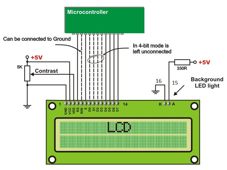
PIC Microcontroller LCD Interfacing Programming
In this tutorial, we will use two pic microcontroller compilers for programming:- MPLAB XC8 Compiler
- MikroC Pro For PIC
LCD Interfacing Programming MPLAB XC8 Compiler
In this section, we will see how to write example code for 16×2 LCD interfacing with PIC18F4550 microcontroller. Although, you can use see code with other Pic microcontrollers also.As we mentioned earlier, we can use the 8-bit mode and 4-bit mode interfacing. But due to the efficient use of MCU pins, we will be using 4-bit Mode. To interface LCD, we follow these steps:- Define PIC18F4450 pin that we want to use for sending commands and data to LCD
- After that send configuration commands to select mode and other configuration settings
- Once we have successfully configured LCD, we can transmit data to LCD.
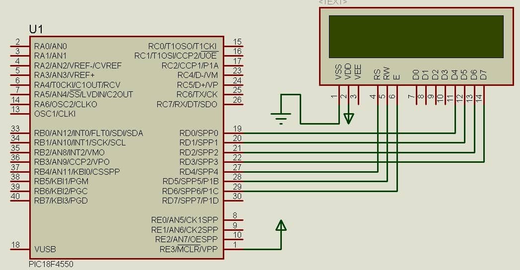
Interfacing Circuit
Make the connections of 16X2 LCD with PIC18F4550 microcontroller according to this circuit diagram.- In this circuit, we used the PORTB of PIC18F4550. But you can use any PORT. To do this, we need to change the pin assignment inside the code. I will show you how to assign pins for LCD in the next section.
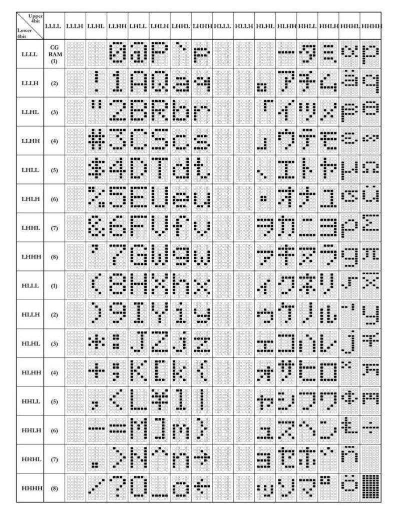
LCD Commands
We use #define directives to define commands that are used for various control functions of the 16×2 display.// Command set for Hitachi 44780U LCD display controller #define LCD_CLEAR 0x01 // It clears everythings #define LCD_HOME 0x02 // set the cursor to first line and first row #define LCD_CURSOR_BACK 0x10 // moves curson one position back #define LCD_CURSOR_FWD 0x14 //moves curson one position forward #define LCD_PAN_LEFT 0x18 // used to scroll text left side to scroll text #define LCD_PAN_RIGHT 0x1C // used to scroll text right side to scroll text #define LCD_CURSOR_OFF 0x0C // stops display curson on screen #define LCD_CURSOR_ON 0x0E // turns on cursor display #define LCD_CURSOR_BLINK 0x0F // curson keeps blinking #define LCD_CURSOR_LINE2 0xC0 // move curson to scond line or second row // display controller setup commands from page 46 of Hitachi datasheet #define FUNCTION_SET 0x28 // 4 bit interface, 2 lines, 5x8 font #define ENTRY_MODE 0x06 // increment mode #define DISPLAY_SETUP 0x0C // display on, cursor off, blink offd
Microcontroller Pin Assignment
These lines define which pins of the pic microcontroller should connect with LCD. For instance, in this example, we used the PORTD of PIC18F4550 microcontroller. Connect RD0-RD3 pins with D4-D7 pins of LCD respectively and other pins with RW, EN, RS and Power pins. But you can change PORT to other PORT of PIC microcontroller also by changing the PORT name with these commands./ These #defines create the pin connections to the LCD in case they are changed on a future demo board #define LCD_PORT PORTD #define LCD_PWR PORTDbits.RD7 // LCD power pin #define LCD_EN PORTDbits.RD6 // LCD enable #define LCD_RW PORTDbits.RD5 // LCD read/write line #define LCD_RS PORTDbits.RD4 // LCD register select line
LCD initialization Function
This function initializes the LCD commands to select 4-bit mode and other configuration settings. It performs the following operations:- Initialize the LCD module
- initializes the LCD driver.
- This routine must be called before any other LCD routine is called
void LCD_Initialize()
{
LCD_PORT = 0; // clear latches before enabling TRIS bits
TRISD = 0x00;
LCD_PWR = 1; // power up the LCD
__delay_ms(LCD_Startup); // required by display controller to allow power to stabilize
LCDPutCmd(0x32); // required by display initialization
LCDPutCmd(FUNCTION_SET); // set 4-bit interface mode and 16x2 of lines and font
LCDPutCmd(DISPLAY_SETUP); // turn on display and sets up cursor
DisplayClr();
LCDPutCmd(ENTRY_MODE); // set cursor movement direction

}
Sending data in 4-Bit Format
LCDWriteNibble() function is used to write a nibble. Nibble is basically a half a byte. Because we are using LCD in four bits mode. Therefore, we need to send 8-bit commands/data in four bits chunks. This function writes the specified nibble to the LCD.void LCDWriteNibble(char ch, char rs)
{
ch = (ch >> 4); // always send the upper nibble
ch = (ch & 0x0F); // mask off the nibble to be transmitted
LCD_PORT = (LCD_PORT & 0xF0); // clear the lower half of LCD_PORT
LCD_PORT = (LCD_PORT | ch); // move the nibble onto LCD_PORT
LCD_RS = rs; // set data/instr bit to 0 = insructions; 1 = data
LCD_RW = 0; // RW - set write mode
LCD_EN = 1; // set up enable before writing nibble
LCD_EN = 0; // turn off enable after write of nibble
}Sending Commands to LCD
Because we will use 4-bit mode, data and commands transfer in 4-bits format. Even it requires at least 8-bit to display a character. To resolve this issue, we send data in a 4-bits format two times.LCDPutCmd() function sends an ASCII command to the LCD in instruction mode. This routine writes a character to the LCD command register.void LCDPutCmd(char ch)
{
__delay_ms(LCD_delay);
LCDWriteNibble(ch,instr); //Send the higher nibble
ch = (ch << 4); //get the lower nibble
__delay_ms(1);
LCDWriteNibble(ch,instr); //Now send the lower nibble
}- void LCDPutChar(char ch): Writes a character to LCD at current cursor position. This function displays the specified ASCII character at the current position on the LCD.
- void LCDPutStr(const char *): This routine writes a string to LCD at current cursor position
- LCDGoto(char pos, char ln): This function positions the cursor at the specified line and column. Column and line at which the cursor should be positioned between 0-15 for pos (column) and 0-1 for ln(row).
LCD Interfacing Code MPLAB XC8 Compiler
This is a complete code. Before using this code, make sure to include a configuration header file “newxc8_header.h”. You can generate a header file by going to the memory window in MPLAB XC8 Compiler.#include <xc.h>
#include <stdio.h>
#include <string.h>
#include <stdlib.h>
#include "newxc8_header.h"
#define _XTAL_FREQ 8000000
#define __delay_ms(x) _delay((unsigned long)((x)*(_XTAL_FREQ/4000.0)))
// set up the timing for the LCD delays
#define LCD_delay 5 // ~5mS
#define LCD_Startup 15 // ~15mS
// Command set for Hitachi 44780U LCD display controller
#define LCD_CLEAR 0x01
#define LCD_HOME 0x02
#define LCD_CURSOR_BACK 0x10
#define LCD_CURSOR_FWD 0x14
#define LCD_PAN_LEFT 0x18
#define LCD_PAN_RIGHT 0x1C
#define LCD_CURSOR_OFF 0x0C
#define LCD_CURSOR_ON 0x0E
#define LCD_CURSOR_BLINK 0x0F
#define LCD_CURSOR_LINE2 0xC0
// display controller setup commands from page 46 of Hitachi datasheet
#define FUNCTION_SET 0x28 // 4 bit interface, 2 lines, 5x8 font
#define ENTRY_MODE 0x06 // increment mode
#define DISPLAY_SETUP 0x0C // display on, cursor off, blink offd
#define LCDLine1() LCDPutCmd(LCD_HOME) // legacy support
#define LCDLine2() LCDPutCmd(LCD_CURSOR_LINE2) // legacy support
#define shift_cursor() LCDPutCmd(LCD_CURSOR_FWD) // legacy support
#define cursor_on() LCDPutCmd(LCD_CURSOR_ON) // legacy support
#define DisplayClr() LCDPutCmd(LCD_CLEAR) // Legacy support
//----------------------------------------------------------------------
// Definitions specific to the PICDEM 2 Plus
// These apply to the Black (2011) version.
//----------------------------------------------------------------------
// single bit for selecting command register or data register
#define instr 0
#define data 1
// These #defines create the pin connections to the LCD in case they are changed on a future demo board
#define LCD_PORT PORTD
#define LCD_PWR PORTDbits.RD7 // LCD power pin
#define LCD_EN PORTDbits.RD6 // LCD enable
#define LCD_RW PORTDbits.RD5 // LCD read/write line
#define LCD_RS PORTDbits.RD4 // LCD register select line
#define NB_LINES 2 // Number of display lines
#define NB_COL 16 // Number of characters per line
void LCD_Initialize(void);
void LCDPutChar(char ch);
void LCDPutCmd(char ch);
void LCDPutStr(const char *);
void LCDWriteNibble(char ch, char rs);
void LCDGoto(char pos, char ln);
void main(void)
{
OSCCON=0x72; // Select internal oscillator with frequency = 8MHz
LCD_Initialize();
LCDPutStr(" Hello World!"); //Display String "Hello World"
LCDGoto(8,1); //Go to column 8 of second line
LCDPutChar('1'); //Display character '1'
DisplayClr(); // Clear the display
LCDPutStr(" LCD Display"); // Dispay a string "LCD Display"
LCDGoto(0,1); //Go to second line
LCDPutStr("Micro Lab"); //Display String "Micro Lab"
while (1)
{
// Add your application code
}
return;
}
void LCD_Initialize()
{
// clear latches before enabling TRIS bits
LCD_PORT = 0;
TRISD = 0x00;
// power up the LCD
LCD_PWR = 1;
// required by display controller to allow power to stabilize
__delay_ms(LCD_Startup);
// required by display initialization
LCDPutCmd(0x32);
// set interface size, # of lines and font
LCDPutCmd(FUNCTION_SET);
// turn on display and sets up cursor
LCDPutCmd(DISPLAY_SETUP);
DisplayClr();
// set cursor movement direction
LCDPutCmd(ENTRY_MODE);
}
void LCDWriteNibble(char ch, char rs)
{
// always send the upper nibble
ch = (ch >> 4);
// mask off the nibble to be transmitted
ch = (ch & 0x0F);
// clear the lower half of LCD_PORT
LCD_PORT = (LCD_PORT & 0xF0);
// move the nibble onto LCD_PORT
LCD_PORT = (LCD_PORT | ch);
// set data/instr bit to 0 = insructions; 1 = data
LCD_RS = rs;
// RW - set write mode
LCD_RW = 0;
// set up enable before writing nibble
LCD_EN = 1;
// turn off enable after write of nibble
LCD_EN = 0;
}
void LCDPutChar(char ch)
{
__delay_ms(LCD_delay);
//Send higher nibble first
LCDWriteNibble(ch,data);
//get the lower nibble
ch = (ch << 4);
// Now send the low nibble
LCDWriteNibble(ch,data);
}
void LCDPutCmd(char ch)
{
__delay_ms(LCD_delay);
//Send the higher nibble
LCDWriteNibble(ch,instr);
//get the lower nibble
ch = (ch << 4);
__delay_ms(1);
//Now send the lower nibble
LCDWriteNibble(ch,instr);
}
void LCDPutStr(const char *str)
{
char i=0;
// While string has not been fully traveresed
while (str[i])
{
// Go display current char
LCDPutChar(str[i++]);
}
}
void LCDGoto(char pos,char ln)
{
// if incorrect line or column
if ((ln > (NB_LINES-1)) || (pos > (NB_COL-1)))
{
// Just do nothing
return;
}
// LCD_Goto command
LCDPutCmd((ln == 1) ? (0xC0 | pos) : (0x80 | pos));
// Wait for the LCD to finish
__delay_ms(LCD_delay);
}
/**
End of File
*/Simulation Result
Now upload this code to PIC18F4550 microcontroller, you will see this result on LCD.
How to Display Integer Value on LCD
In last section, we have seen how to display ASCII characters or string. But in almost all practical projects, we need to display, integer, float values. This code displays the counter value which increments from 0-9 after every one second. This is the main function of code only. Because the rest of the code is same as the previous program example.void main(void)
{
OSCCON=0x72; // Select internal oscillator with frequency = 8MHz
LCD_Initialize();
LCDPutStr("Counter = "); //Display String "Hello World"
// Clear the display
__delay_ms(1000);
int counter=0; // define a integer type variable as a counter
char buffer[10]; //used to store counter string
while (1)
{
sprintf(buffer,"%d",counter); // Converts counter integer value into string
LCDGoto(10,0); //Go to column 10 of first line
LCDPutStr(buffer); // display counter value
__delay_ms(1000);
counter++;
if(counter>=10)
counter=0;
}
return;
}
LCD Interfacing using MikroC for PIC
In this section, we will see how to interface LCD with pic microcontroller and programming examples using MikroC for pic. MikroC pro has a built-in library.MikroC Pro LCD library
LCD Display Commands in Mikro c for pic
We have used 16×2 LCD which means there are 2 rows and 16 characters in each row. So we can display a total of 32 characters at a time in two rows with 16 characters in each row.
- Void Lcd_Out (char row, char column, char*text);
This is the main command which prints our text on LCD. It also gives the privilege to specify the position of the text. In the horizontal direction, we count rows number and in a vertical direction, we count the column number. In above command,
- Row specifies the starting position of text in row. We specify the number of the row like 1 or 2 according to our requirement in which row we want to print text.
- Column specifies the starting position of text in the column. We specify the number of column-like (1,2,3,..16) according to our requirement in which row we want to print text.
- Text specifies the text we want to display on LCD
For example the command Lcd_Out (1, 1, “LCD”); will print the text LCD starting from a position of row 1 and column 1.
Lcd_Out (2, 1, “LCD”); will print the text LCD starting from position of row 2 and column
Lcd_Out (1, 5, “LCD”); will print the text LCD starting from position of row 1 and column 5.
However if your string is longer than the number of characters that could be displayed in a row from the starting position, the last characters will not be displayed. E.g. Lcd_Out (1, 6 “LCD Interface”); will display text in row 1 starting from column position 6 and will display only LCD Interface the rest of the characters will not be displayed as there is no room for them.
- void Lcd_Out_Cp(char *text); will start printing the text from the current cursor position. For example after printing Lcd_Out (1, 1, “LCD”); if you write Lcd_Out_Cp(“Hello”); it will display “Hello” at a position from column position of 4 in row 1.
- void Lcd_Chr(char row, char column, char out_char); allows only single characters to be displayed at specified positions. E.g. Lcd_Chr(2, 5, ‘A’); will print only A on column 5 row 2.
- void Lcd_Chr_Cp(char out_char); allows to print only single character from current cursor position like after Lcd_Chr(2, 5, ‘A’); if your write Lcd_Chr_Cp(‘B’); it will be printed at row 2 column 6.
LCD Interfacing with PIC16F877A MikroC Pro
To interface LCD with PIC16F877A and display the text ‘LCD INTERFACE’ on it. LCDs come in different sizes and shapes. For this project, we have selected a 16×2 character, alphanumeric LCD. It contains 2 rows of 16 character.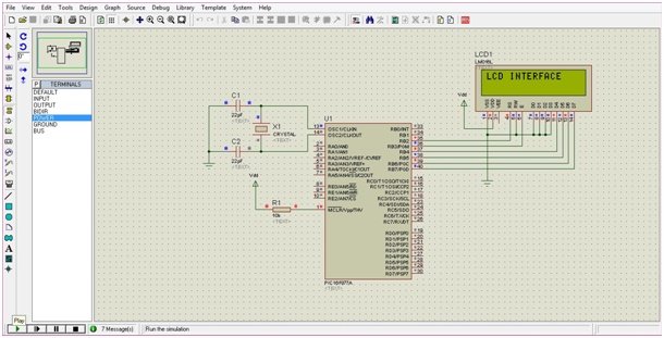
LCD Connections with pic microcontroller
- Connect pin1 of LCD to ground and pin2 to Vdd.
- Pin3 of LCD is used to adjust the contrast of the display. Leave it unconnected.
- RS (pin4) of LCD is connected to RB2 of PORTB. It distinguishes between data input and command input.
- RW (pin5) is grounded since we have to write the data on LCD.
- E (pin6) is connected to the RB3 of PORTB. It is a control line to inform the LCD that data has been sent.
- D0-D3 of the LCD are grounded since we are using a 4-bit mode. D4-D7 are connected to the PORTB pins (RB4-RB7) of the controller.
LCD Interfacing Code MikroC
Write the following code in mikroC Compiler
/* LCD INTERFACING WITH PIC16F877A */

// LCD Module connections

sbit LCD_RS at RB2_bit;

sbit LCD_EN at RB3_bit;


sbit LCD_D7 at RB7_bit;

sbit LCD_D6 at RB6_bit;

sbit LCD_D5 at RB5_bit;

sbit LCD_D4 at RB4_bit;

// End LCD module connections

// LCD Pin direction

sbitLCD_RS_Direction at TRISB2_bit;

sbitLCD_EN_Direction at TRISB3_bit;

sbit LCD_D7_Direction at TRISB7_bit;

sbit LCD_D6_Direction at TRISB6_bit;

sbit LCD_D5_Direction at TRISB5_bit;

sbit LCD_D4_Direction at TRISB4_bit;

// End of LCD Pin direction

void main() {

Lcd_Init();// Initialize LCD

Lcd_Cmd(_LCD_CLEAR);// Clear Display

Lcd_Cmd(_LCD_CURSOR_OFF); // Cursor Off

Lcd_Out(1,1,"LCD INTERFACE");// Write "LCD INTERFACE" in the first row

}
When using PIC microcontroller, the mikroC compiler has a built-in LCD library that supports the commands to carry out LCD initialization. The library consists of a number of functions to control LCDs with 4-bit data interface.
The main program first clears the LCD screen and then displays “LCD INTERFACE” in the first row of LCD. The LCD pin directions are all set as outputs. The RS pin of LCD is set to 1, which indicates that the information received from DB4-DB7 is a valid text to be printed on LCD screen. The EN pin is also set to 1 which indicates that data is send to the LCD.
Cursor Position Control Example
This code will be used to display characters on cursor location and specific location on LCD.// LCD Module connections
sbit LCD_RS at RB1_bit; // it can only access a pin not a port
//sbit LCD_RS at LATB1_bit; //same as "sbit LCD_RS at RB1_bit;"
//sbit LCD_RS at LATB.B1; //SAME AS "sbit LCD_RS at RB1_bit;"
//sbit LCD_RS at LATB;
//sbit LCD_RS at PORTB1_bit;
//sbit LCD_RS at PORTB.B1;
//sbit LCD_RS at PORTB;
sbit LCD_EN at RB0_bit;
sbit LCD_D7 at RB5_bit;
sbit LCD_D6 at RB4_bit;
sbit LCD_D5 at RB3_bit;
sbit LCD_D4 at RB2_bit;
// End LCD module connections
// LCD Pin direction
sbit LCD_RS_Direction at TRISB1_bit;
sbit LCD_EN_Direction at TRISB0_bit;
sbit LCD_D7_Direction at TRISB5_bit;
sbit LCD_D6_Direction at TRISB4_bit;
sbit LCD_D5_Direction at TRISB3_bit;
sbit LCD_D4_Direction at TRISB2_bit;
// End of LCD Pin direction
void main()
{
ANSELH = 0X00;
TRISB=0X00;
PORTB=0X00;
Lcd_Init();// Initialize LCD
Lcd_Cmd(_LCD_CLEAR);// Clear Display
Lcd_Cmd(_LCD_CURSOR_OFF); // Cursor Off
while (1)
{
Lcd_Out(1,6,"LCD");// Write “LCD INTERFACE” in the first row
Delay_ms(1000);
Lcd_Out_Cp("Hello");
Delay_ms(1000);
Lcd_Chr(2, 7, 'i');
Delay_ms(1000);
Lcd_Chr_Cp('A');
Delay_ms(1000);
Lcd_Cmd(_LCD_RETURN_HOME);
Delay_ms(1000);
Lcd_Chr_Cp('B');
Delay_ms(1000);
Lcd_Cmd(_LCD_CURSOR_OFF) ;
Lcd_Chr_Cp('C');
Delay_ms(1000);
Lcd_Cmd(_LCD_UNDERLINE_ON) ;
Lcd_Chr_Cp('D');
Delay_ms(1000);
Lcd_Cmd(_LCD_BLINK_CURSOR_ON) ;
Lcd_Chr_Cp('E');
Delay_ms(1000);
Lcd_Cmd(_LCD_TURN_OFF) ;
Lcd_Chr_Cp('F');
Delay_ms(1000);
Lcd_Cmd(_LCD_TURN_ON) ;
Lcd_Chr_Cp('G');
Delay_ms(1000);
Lcd_Cmd(_LCD_SHIFT_LEFT) ;
Delay_ms(1000);
Lcd_Cmd(_LCD_CLEAR);
Delay_ms(1000);
}
}Applications
Programmed LCDs are vastly used for industrial as well as commercial applications. LCDs are used in UPSs or inverters, where voltage and current readings are displayed on the screen. Instructions to be followed are displayed on an LCD screen in airports, banks, hospitals, etc. If you still have any issue after reading this article, feel free to comment on this post with your issues.
thanks man. this has been very helpful. which software do you use to simulate or design the circuit diagram?
mikro c for pic and proteus
sir will u send me the ckt diagram for speed control of single phase ac motor tnx
really good to understand
It sensor explain
sir i want micro-c program for my project which is forward collision avoidance system for automobiles.
Dear informer I am using a PIC16F877A connecting to an LCD 16 x2 model No:LCD1602A the programed PIC16F877A been tried in two deferent ways but I can not get the display to show the programd Data the connections are as falowed
the last tried one
——————-
LCD PIC
D4——D0
D5——D1
D6——D2
D7——D3
R/S—-B2
EN—–B1
LCD 1602A Power and unused connetions
PIN1 VSS
pin 2 &16 VDD 5V
PIN 3 VO
PIN 5 7 8 9 10 15: VSS
The first try
LCD PIC
D7——-B0
D6——B1
D5——B3
R/S—-B4
EN—–B5
Other conne ctions are as above mentioned the unused pins are connected to VSS.
SIR, I WANT PROGRAM FOR LCD DISPLAY USING CC32OO MICRO CONTROLLER
thanks man
Thank u for information..its very use full my project wrk…thank u so much
i want the progrmming CODE WITH Explanation for scada based power monitoring and controlling in machines.
I want assembly langiage program for interfacing of lcd with pic16f877a
you can convert existing c code into assembly code.
when you compile the code, you will get asm file also
please help me i want LCD INTERFACING WITH PIC16F877A MICROCONTROLLER and display a counter 0 a 99 please code
can you help me with the connection of pic16f877a and LCD. my connections are
pin 40 pic to pin 14 of LCD
pin 39 pic to pin 13 of LCD
pin 38 pic to pin 12 of LCD
pin 37 pic to pin 11 of LCD
pin 36 pic to pin 6 of LCD
pin 35 pic to pin 4 of LCD
pins of LCD 1 & 5 connected to ground
pin 1 is connected to 5V of LCD
pins of pic 1,32, 11 are connected to 5V
pins of pic 12,31 are connected to ground
else are no connected
for getting the result what i have to do. pls help me
check setting bit connection specified at the start of program
pls send me d code for writing a text for an input pin at low and high
Sir How can I interface LCD 16 by 2 with PIC16F877A,so that the first line of the LCD will be moving and returning without stppping
i tried this not working help
sbit LCD_RS at RE0_bit;
sbit LCD_EN at RE2_bit;
sbit LCD_D4 at RD4_bit;
sbit LCD_D5 at RD5_bit;
sbit LCD_D6 at RD6_bit;
sbit LCD_D7 at RD7_bit;
sbit LCD_RS_Direction at TRISE0_bit;
sbit LCD_EN_Direction at TRISE2_bit;
sbit LCD_D4_Direction at TRISD4_bit;
sbit LCD_D5_Direction at TRISD5_bit;
sbit LCD_D6_Direction at TRISD6_bit;
sbit LCD_D7_Direction at TRISD7_bit;
// End LCD module connections
void main()
{
Lcd_Init(); // Initialize LCD
Lcd_Cmd(_LCD_CLEAR); // Clear display
Lcd_Cmd(_LCD_CURSOR_OFF); // Cursor off
Lcd_Out(1,1,”Hello World”); // Write text’Hello World’ in first row
}
hi dear Bilal
I am using PIC16 F877A with drive frequency 8MHz crystal
I have calculated the delay timing as fallow
65536-((7*8000000)/(65536*4)) that gives me= 653 . for 7 secs result
when I get the LED s to drive by NPN transistor the out put volt dose n´t have enough current to drive
I tried with a NAND gate IC by entering the PIC outputs the inputs of NAND gate IC, it turns ON the NPN transistor
but switching ON time is not Ending.should I use Higher drive frequency crystals or….?
wr Nasim
sir i want to lesson about micro controller programming
Hi Dear Bilal,
Is there anyway to connect two LCD displays to one PIC16F877A and show different text in those displays…?
I have been looking for information about LCDs. What I am trying to do is program a LCD read out for a test vehicle I am working on. What I need is to preprogramed LCD readout that when an input is put to it will simply go and display the readout. Actually real simple system, but I do not have the knowledge or know where to start. Example would be like if the Oil Pressure unit is energized, so a positive 12vdc would then turn on the written display and state that the pressure system is having a problem, or something like that. Same as if fuel is low it will give me a readout. So I will also need to build a voltage system that could be used over from 0 to lets say 13.4 dcv. The main problem is designing the readout, preprogramed readout, where all it needs is a simple input to make it operate. If you could be of any help it would be appreciated. Thank You, Greg
It is possible and you need a circuit to sense different pressure levels, take that data as input. Keep your preset levels in memory and compare the same. when your input data matches the preset level trigger the display message on your LCD. Message could be anything you want within the range of 32 characters.
Dear SIr,
with due respect it is stated that i need a code of pic micro for interfacing LCD 16*2 with PIC Micro
Dear: Do mean I should send a copy of component charter softwate that I have been using?
how to cantrollbrightness in 16*2 led display with the arduino.uno.
i am interfacing LCD 12864 (128×64)and i give the text but it displays only few seconds after there is no text was displayed please help me in displayin senter of the screen and life span of the text .
Hi sir,In case of resistance is out of range, ” the system must give a warning as well” how can add this part to the code? help please
Sir I want to know the pcb design of the project
This code does not display anything for me. Any suggestions. I am using PIC18F14Q40 and also changed pin to PORTC. I chose 8MHz oscilator.
I have tried coding in microc for LCD interfacing but after hit the build operation undeclare error is appearing for Lcd_Init, Lcd_out etc all command which are write inside void main
Make sure to include LCD library from library manager in MikcroC.
interfacing pic16f877a and lcd and 2 digital input?
help anyone?
any help will be apriciated
sir, i want intefacing 20x4lcd display in pic16f877a program please help me sir i needed this program…
hello sir good evening,how to display 20×04 lcd display in timer updown seconds counter using pic16f877a program sir…plz help m
Assalamo Alaikum sir
How can we disply this on pic16f676
Please modified send me this cod for 16f676