Interrupts stops the CPU program from normal execution and ask it to serve first what appear as a interrupt. CPU does not know when these interrupt will happen, so CPU will keep doing its normal execution until interrupt occurs. For example the microcontroller does not know when a user will press a button, so the microcontroller will continue its operation until a interrupt is received. So the CPU keeps on doing its normal job, which may be for example read temperature using LM35 sensor and display on LCD.
The CPU will start on doing the current job but as soon as the interrupt occurs presses the button it informs the CPU using an interrupt. The CPU will store its current process and go to interrupt service routine where we can process the command or put it in a FIFO (First in First Out) queue (to process latter). The ISR is usually very small in microcontrollers and works very fast. As soon as the ISR ends, the CPU restores its saved state and resumes where it left. In such a way CPU does not skipped any instruction. you may also like to check complete list of pic microcontroller tutorials.
Recommended Components
The following components are used in this project or are helpful for building it with a PIC microcontroller.
| Component | How it’s used in this project | Buy on Amazon |
|---|---|---|
| PIC16F877A microcontroller | Main MCU whose timer module generates the interrupt in this tutorial. | Check Price |
| PICkit 5 programmer/debugger | Programs and debugs the PIC16F877A over the ICSP interface. | Check Price |
| 5mm LED | Toggled inside the timer interrupt service routine to show the timing. | Check Price |
| Breadboard | Solderless base for wiring the PIC and the indicator LED. | Check Price |
| Jumper Wires | Connect the MCU pins, power rails and the LED on the breadboard. | Check Price |
As an Amazon Associate we earn from qualifying purchases. Prices and availability are accurate as of the date/time indicated and are subject to change.
Sources of Interrupts in pic microocntroller

How Interrupts are managed

Timers in pic microcontrollers
.As the name implies, timers can tell the time and count. Counting and timing allows for some really cool things, like controlling the brightness of LEDs, controlling the angle of servo shafts, receiving sensor data that transmit in PWM (Pulse-Width-Modulation), making a timer (like on the stove), or just simply adding a time variable to your microcontroller project.
But first, it’s important to know that there is a clock inside (or outside) the microcontrollers. In our case we use crystals that resonate on high frequency to produce a consistent clock signal required by the Microcontrollers. Microcontrollers need clocks so that our programs can be executed in rhythm with the clock. This is the basic function of microcontrollers. A basic instruction is processed when a tick from the clock passes. Microcontrollers with timers functionality have an internal register, the value of which increments automatically with the passage of time. The timer and counter functions in the microcontroller simply count in sync with the microcontroller clock. However, the timer can only count up to either 255(8-bit timer register), or 65535 (16-bit timer register). That’s far from the 4,000,000 ticks per second Generated from a 4Mhz crystal.
When a 8 bit timer register’s value exceeds 256, it again starts from zero. This is known as timer overflow. For us this event has serious importance. Every time a timer register overflows, a special function know as Timer interrupt service routine starts executing. Similarly for a 16 bit timer, Timer ISR launches whenever the value of timer exceeds 65,535. The Timer ISR always launches whatever your microcontroller may be doing, or whichever functions it might be executing. Whenever a timer overflow occurs, Timer ISR will surely launch.
In our labs, we normally use very high frequency crystals, and we don’t want our timer register overflowing too rapidly and the timer ISR being called again and again, so we need to call our timer less frequently and for that the frequency of crystal must be divided to a smaller value.
PIC 16 microcontrollers have a built in hardware that divides the crystal oscillation frequency by 4. So a 4Mhz crystal connected externally will have its frequency divided by 4 and the hardware feels as if the crystal was just 1Mhz. The microcontroller provides a very useful feature called prescaling. Prescaling is simply a way for the timer to skip a certain number of microcontroller clock ticks. So in simple words, rather than incrementing the timer register on every tick from the microcontroller’s clock, we would increment timer register every 8, 64, or 256 ticks. The PIC microcontrollers allow prescaling (skipping) numbers of: 1, 2, 4, 8, 16, 64, 128, 256.
Our uController 18F46K22 has 3 8-bit and 4 16-bit timers.
Timer TMR0 in pic microcontroller
The timer TMR0 module is an 8-bit timer/counter with the following features:
- Software selectable operation as a timer or counter in both 8-bit or 16-bit modes;
- 8-bit prescaler.
- Programmable internal or external clock source.
- Interrupt on overflow.
- Programmable external clock edge selection.
Some Important Special Function Registers that control the Timer0 are listed below


Turning On Timer 0: T0CON Register
- Set TMR0ON to 1 to turn on the timer.
- Set T08BIT to select between 8 and 16 bit operation.
- Set T0CS to select clock source. We will set it to zero since we want the timer to increment from internal clock.
- Set bit 0-3 to select appropriate prescaler.
Turning on Timer 0 Interrupts: INTCON Register
- Set GIE to 1 to enable global interrupts.
- Set TMR0IE to 1 to enable timer0 interrupts.
Example how to generate square wave of 10m WITH PIC MICROCONTROLLER TIMERS
- Given PIC18F46K22 with 4 MHz crystal. Write code for timer0 in 8 bit mode that produces square wave of 10ms.
- Square wave of period 10 ms means that the output of uController must change every 5ms.
- Crystal oscillates at 4 MHz, means that internal frequency received by the timer is = 4/4 Mhz = 1Mhz.
- To generate 5ms interrupt we require (5/1000)*1M ticks = 5000 ticks.
- Since our timer is in 8bit mode. It can only tick up to 256 ticks. So we must use a presaler.
- If prescaler is 1:4, then ticks required are 5000/4 = 1250. Still larger than 255.
- if prescaler is 1:32, then ticks required are 5000/32 = 157. This means that we set our prescaler at 1:32, our timer will count upto 157 in 5ms. But interrupt will still be generated when timer overflow (counts to 256).
- How do we make sure our timer overflows after 156 increments?
- Every time the timer overflows, We fill it with (255-157) = 98.
So we need: Preload Value = 98; Prescaler = 1:32;
void interrupt(){      //This function is called on each interrupt

   if (TMR0IF_bit) {   //Check if Timer0 has caused the interrupt

      LATB = ~LATB;    //Toggle PORT to generate square wave

      TMR0IF_bit = 0;         // clear interrupt flag

      TMR0L = 98;             // Preload timer0

   }

}


void main() {

   ANSELB = 0;              // Configure AN pins as digital

   TRISB  = 0;              // PORTB is output

   LATB = 0;             // Initialize PORTB


   TMR0L = 98;               // Timer0 preload value

   T0CON = 0xC4;// = 0b11000100  Set TMR0 to 8bit mode and prescaler to 32

   GIE_bit = 1;             // Enable global interrupt//INTCON.B7

   // You can also set GIE_bit like INTCON.B7 = 1; and INTCON.GIE = 1;


   TMR0IE_bit = 1;          // Enable Timer0 interrupt//INTCON.B5

   // Equivalent to INTCON.B5 = 1; and INTCON.TMR0IE = 1;


   while(1);

}
10KHZ square wave using pic18f46k22 microcontroller
The code given below will generate a 10KHZ square wave on PORTB of PIC18F46K22 microcontrollershort dummy=0;
short ticks=0;
void interrupt(){ //This function is called on each interrupt
if (INT0F_bit) { //Check if Timer0 has caused the interrupt
dummy=PORTB;
TMR0L=0;
TMR0H=0; //Toggle PORT to generate square wave
TMR0IF_bit = 0; // clear interrupt flag
TMR0L = 98; // Preload timer0
}
}
void main() {
OSCCON.IRCF0=1;
OSCCON.IRCF1=0;
OSCCON.IRCF2=1;
ANSELB = 0; // Configure AN pins as digital
TRISB = 0; // PORTB is output
LATB = 0; // Initialize PORTB
TMR0L = 00; // Timer0 preload value
T0CON = 0b11000111;// = 0b11000100 Set TMR0 to 8bit mode and prescaler to 32
INTCON=0b11010000;
GIE_bit = 1; // Enable global interrupt//INTCON.B7
// You can also set GIE_bit like INTCON.B7 = 1; and INTCON.GIE = 1;
// Enable Timer0 interrupt//INTCON.B5
// Equivalent to INTCON.B5 = 1; and INTCON.TMR0IE = 1;
while(1);
}Timer start with external interrupt using pic18f46k22 pic microcontroller
Connect a button on any pin and when you press it for the first time, the timer should be switched on generating a 4 kHz square wave. When you press it for the second time, the timer should be switched off.short dummy=0;
void interrupt(){ //This function is called on each interrupt
if (TMR0IF_bit) { //Check if Timer0 has caused the interrupt
LATD = ~LATD;
//Toggle PORT to generate square wave
TMR0IF_bit = 0; // clear interrupt flag
TMR0L = 0x82;
TMR0H =0xff; // Preload timer0
}
if (INT0F_bit) //|RBIF_bit)
{ dummy=PORTB;
TMR0L = 0x82;
TMR0H =0xff;
TMR0ON_bit=~TMR0ON_bit;
TMR0IE_bit=~TMR0IE_bit;
// RBIF_bit=0;
INT0F_bit=0;
LATD=0x00;
}
}
void main() {
OSCCON.IRCF0=1;
OSCCON.IRCF1=0;
OSCCON.IRCF2=1;
ANSELB = 0; // Configure AN pins as digital
TRISB = 0xff;
ANSELD=0;
TRISD=0;
LATD=0x00; // PORTB is input
LATB = 0; // Initialize PORTB
TMR0L = 0x82;
TMR0H= 0xFF; // Timer0 preload value
T0CON = 0x08;
INTCON=0xD8;
GIE_bit = 1;
INTCON.PEIE= 1; // Enable global interrupt//INTCON.B7
while(1);
} Piano using pic microcontroller timers
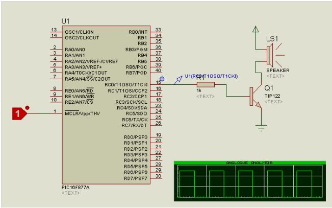 Now that you have learnt to create square waves on any pin, make a 3 button piano. Upon pressing a specific key, a specific tone should play on the speaker
short dummy=0;
void interrupt(){
 short dummy=0;
 //This function is called on each interrupt
 if (TMR0IF_bit) { //Check if Timer0 has caused the interrupt
 LATD = ~LATD;
 //Toggle PORT to generate square wave
 TMR0IF_bit = 0; // clear interrupt flag
 return;

}
 else if (INT0F_bit) //|RBIF_bit)
 { dummy=PORTB;
 T0CON = 0x40;
 INTCON2.INTEDG0=~INTCON2.INTEDG0;
 TMR0ON_bit=~TMR0ON_bit;
 TMR0IE_bit=~TMR0IE_bit;
 // RBIF_bit=0;
 INT0F_bit=0;
 LATD=0x00;
 return;
 }
 else if (INT1F_bit) //|RBIF_bit)
 { dummy=PORTB;
 T0CON = 0x41;
 INTCON2.INTEDG1=~INTCON2.INTEDG1;
 TMR0ON_bit=~TMR0ON_bit;
 TMR0IE_bit=~TMR0IE_bit;
 // RBIF_bit=0;
 INT1F_bit=0;
 LATD=0x00;
 }

else if (INT2F_bit) //|RBIF_bit)
 { dummy=PORTB;
 T0CON = 0x42;
 INTCON2.INTEDG2=~INTCON2.INTEDG2;
 TMR0ON_bit=~TMR0ON_bit;
 TMR0IE_bit=~TMR0IE_bit;
 // RBIF_bit=0;
 INT2F_bit=0;
 LATD=0x00;
 }
}

void main() {

OSCCON.IRCF0=1;
 OSCCON.IRCF1=0;
 OSCCON.IRCF2=1;

ANSELB = 0; // Configure AN pins as digital
 TRISB = 0xff;
 ANSELD=0;
 TRISD=0;
 LATD=0x00; // PORTB is input
 LATB = 0; // Initialize PORTB

TMR0L = 0x00;
 TMR0H= 0x00; // Timer0 preload value
 T0CON = 0x40;
 INTCON=0xD8;
 GIE_bit = 1;
 INTCON.PEIE= 1;
 INTCON2.INTEDG0=1;
 INTCON2.INTEDG1=1;
 INTCON2.INTEDG2=1; // Enable global interrupt//INTCON.B7
 INTCON3.INT1IE=1;
 INTCON3.INT2IE=1;

while(1);
}
Dear Bilala.Malik
from the time I have started Programming PIC´s I have the same problem of programming configurations
All projects as a beginner I accomplish I see all actions as I have programmed in my laptop ok but when
I send data to the chip I have selected all data goes through to the Chip, but when the chip is set to my Bread board the output voltage is not strong enough to switch ON the LEDs or an NPN Transistor the resistors been used or from 220 ohms to 100 ohms to find the right current go to anode of LED or to the Base of transistor but makes no deference what will be the mistake in programming.
with
Regards
Nasim
Dear Sir,
Please help me for multi function select & program set by keypad like a temperature controller/ VFD parameter set.
TMR0ON_bit &=~ TMR0ON_bit;
TMR0IE_bit &=~ TMR0IE_bit; will respond compared to TMR0ON_bit =~ TMR0ON_bit;
TMR0IE_bit =~ TMR0IE_bit;
TMR0IE_bit &=~ TMR0IE_bit; will respond compared to TMR0ON_bit =~ TMR0ON_bit;
TMR0IE_bit =~ TMR0IE_bit;
my friend, there is no 256 on 8bit… exceding 256 would mean trying 256+1 thats not posible on 8 bits, in case of overflow, carry, etc etc etc, still 8 bits only can have/provide 255 additions to 0. so it never will be >256… not even >255… i know, 255+”0″ means 256… 16*15+15= 0xFFh 16*16 (or *15+16 btw)=> 0x0100h you get me?
cheers =)