Recommended Components
The following components are used in this project or are helpful for building it with a PIC microcontroller.
| Component | How it’s used in this project | Buy on Amazon |
|---|---|---|
| PIC16F877A microcontroller | Sends AT commands over UART to control the GSM module. | Check Price |
| PICkit 5 programmer/debugger | Flashes the GSM interfacing firmware onto the PIC16F877A. | Check Price |
| SIM900A GSM module | The GSM module interfaced over serial for SMS and calls. | Check Price |
| Breadboard | Provides a base for the PIC, level-shifter, and GSM connections. | Check Price |
| Jumper Wires | Links the PIC TX/RX and power lines to the GSM module. | Check Price |
As an Amazon Associate we earn from qualifying purchases. Prices and availability are accurate as of the date/time indicated and are subject to change.
gsm module interfacing with microcontroller
In this article I will discuss, How to interface gsm module with any microcontroller and especially pic microcontroller. How to use gsm module for wireless communication in your projects. Compatibility issues of microcontrollers and gsm module interfacing.How to use gsm module to receive and send sms. I will also post 2-3 gsm based projects.So that you can get idea about its use in your project or application. you may also like to check:
What is GSM ?
Gsm stands for global system of mobile communication.It is used in almost all mobiles used in whole world. According to one report over 2 billion people in whole world using gsm based mobiles.If you have a mobile, you are also using gsm module. But you don’t know what is happening inside your mobile. How your mobile is working to send and receive messages? How gsm inside your mobile is responding to different tasks you are doing with your mobile phone. Mobile phone is a embedded system which have any microcontroller and gsm module inside to perform tasks you assign to your mobile by touch screen or keypad. There are many gsm modules available in market. I will dicuss SIM900D gsm module and its interfacing with microcontroller.
SIM900D module have following features:
- SMS
- CALL
- GPRS
- ADC
- PWM
- Serial communication
- SPI
- Audio interface
- Input/output pins
So every mobile have all above features to become more user friendly.I will discuss these functions in other articles. Because it is not possible to write all things in one article. SIM900D also provide TCP/IP protocol stack to use GPRS data. SIM900D use AT commands for sms , calls and gprs. For more details about gsm module SIM900D I recommend you to go through data sheet of SIM900D.
Precautions before interfacing gsm module with microcontroller
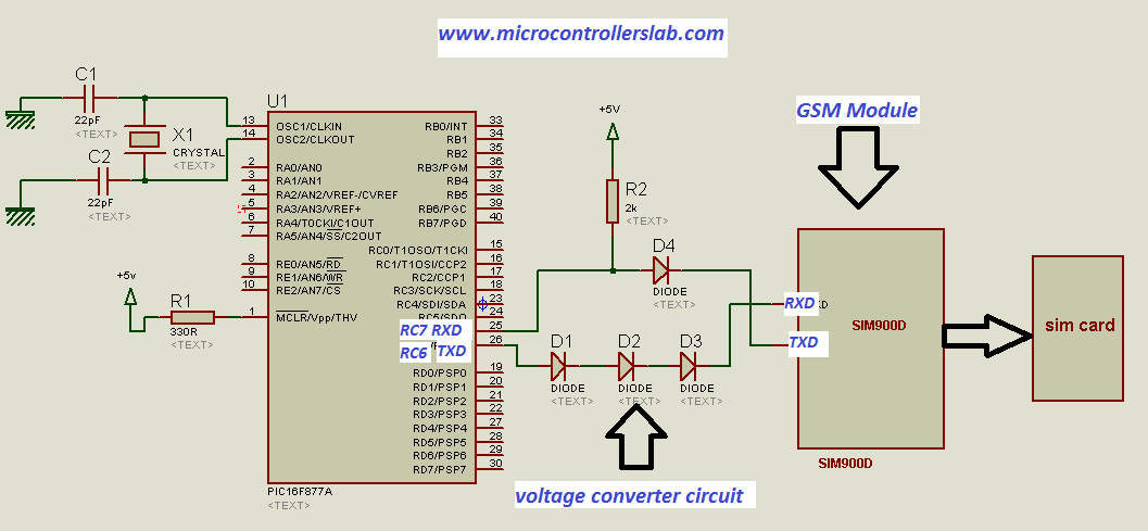
Before interfacing gsm module with microcontroller, it is necessary to check that either the transmit (TXD) and receive (RXD) pins of gsm module and microcontroller are compatible with each other or not. Maximum input voltage to receive(RXD) pins of gsm module is 3 volt and maximum output voltage of transmit(TXD) pins of gsm module is about 2 volt.But the voltage at transmit (TXD) and receive (RXD) pins of pic microcontrollers is about 4 to 5 volt. The transmit pin voltage of pic microcontroller is about 4.5 to 5 volt which is too high for RXD pin of gsm module and voltage at receive (RXD) pin of pic microcontroller is about 4.5-5 volt but transmit(TXD) pin of gsm module have maximum output voltage is 2 volt which is logic zero for pic microcontroller. So there should be voltage converter circuit between pic microcontroller and gsm module. You should also check other microcontrollers compatibility with gsm module before interfacing them with each other. I will disucss voltage converter circuit in interfacing circuit diagram. In some microcontroller you may have no need to voltage converter circuit and they are already comaptible with each other.So you don’t need to use voltage converter circuit for interfacing.
Video lecture on GSM module interfacing
Interfacing of GSM module with PIC16F877A microcontroller
I have used PIC16F877A microcontroller to interface it with SIM900D GSM module. To interface PIC16F877A microcontroller with SIM900D gsm module you only need to connect their transmit and receive pins inversely with each other through voltage converter circuit. By inversely, I mean RXD pin of microcontroller connect with TXD pin of gsm module and TXD pin of microcontroller connect with RXD pin gsm module. we need only these two pin to send message, to receive messgae, to make call and to receive call on gsm module through microcontroller. You may need of other pin while using other features of SIM900D gsm module.
Note : you should purchase a complete gsm module from market which have required external components attach with it . if you purchase only sim900 modem, you have to connect these components by yourself. Components like :
- Antenna
- Sim card jacket
- Network status circuit
- Reset circuit
- power supply connection
- output terminal for RXD and TXD pin
Interfacing diagram is shown below :
In next articles I will discuss how to use above circuit and AT commands to send and receive sms. For more information about gsm articles keep visiting gsm category in my blog.
you may also like
- How to send SMS using GSM module and pic microcontroller
- Wirless temperature sensor using PIC microcontroller and GSM module
If you have any issue in this article, you are welcome to comment on this post.
At the bottom of your article you mentioned that in next article you are going to discuss how to send and receive SMS. I did find an article from you regarding sending SMS but couldn’t find any material on receiving SMS preferably a command SMS for Microcontroller to perform some operation. If you have already written an article on that then could you send me the link to it please if not then would you care to write one for people like me please.
Hope to hearing form you soon.
Salam,
Noman
check these articles
How to send SMS using GSM module and pic microcontroller
Wirless temperature sensor using PIC microcontroller and GSM module
plz provide me the link where u have written the article about interfacing of sim900A with ATmega8
i have to read AT commands frm module and have to send sms to module
plz help me
Thanks
ROHIT
Hi, thaks for your help, i was searching info about tx and rx voltage levels, and i thought that i could connect directly my PIC and SIM900 but i was in a mistake, but i am still confuse about you configuration from sim900 tx to PIC rx , practically the SIM900 is not connected to the PIC, because we have a diode between them…so…why it works?
Hello, in the diagram above, you have connected diode D4 from the RX of the microcontroller to the TX of the GSM module. Should it not be connected in reverse. I think there is a mistake.
No it is correct
it was helpfuLL……..working perfectly
http://microcontrollerslab.com/send-sms-using-gsm-module-pic-microcontroller/ :-> his circuit and AT commands to send and receive sms
Pratik, can u send me the whole program code for this?
Hi Bilal,
I’m the founder of Falphool.com. I was looking for microcontroller and gsm interface for one of my product, I am working upon.
If you have some spare bandwith please do let me know.
Thanks
~Sunil
contact me at microcontrollerslabhub@gmail.com if you need my project assistance
Hi bilal
whats the value of diode in the converter circuit and also pl explain the working of D4 side of the circuit. how it is not influencing the Tx side of Gsm as the 5v will pass through the diode D4 and can destroy the Gsm modem. Pl reply
how do i measure temp and other quantities
using adc and send the result via sms pls reply. tnx
Hi, what is the source code for the PIC?
I would like to have the code so I can build a project that I’m working on for a while but, I can’t get any help from anyone.
Thanks !
Hi Bilal,
What types of diodes shall be used for voltage converter. Can you tell specific model?
Thanks and regards
Please tell me which is the diode model ?
Can I connect 8051 Rx & Tx pin to directly Tx & Rx pin of gsm modem i.e. without using voltage converter circuit?
Hi, I was reading your article and it´s helping me a lot. Checking your diagram out ,made in Proteus, I have a question, if GSM module datasheet says that RXD has to be pulled out to VDD-EXT externally, why you pulled out TXD instead?
thanks for your article, I wait for your answer.
sir, you are doing great job thanks a lot.
I have a question that after you write message, you press cntr+z together or seperately or you write different?