Send SMS using a GSM module and PIC microcontroller: This article explains how to send SMS using a GSM module and PIC microcontroller. It also covers the use of AT commands for sending and receiving SMS. I have already posted an article on GSM module interfacing with PIC microcontroller. I suggest you go through that article before proceeding with this one so that you can get an idea about the GSM module SIM900D, its features, and the interfacing circuitry. There are many GSM-based projects that you may be interested in making using this module.
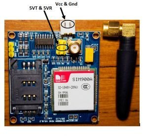
SIM900A GSM Module
SIM900A is an ultra-compact and reliable wireless module. It provides a complete Dual-band GSM/GPRS solution in a Surface Mount Technology (SMT) module, which can be easily integrated into customer applications. This module offers an industry-standard interface and delivers excellent performance for voice, SMS, Data, and Fax over GSM/GPRS 900/1800 MHz frequencies. Its small form factor (24mmx24mmx3mm) and low power consumption make it suitable for various user applications, especially those with slim and compact design requirements. For more information about SIM900A, you can find the SIM900A pinout details in the following link: SIM900A pinout.
SIM900A GSM Module Features
The SIM900A GSM Module offers several features, including:
- Dual-Band 900/ 1800 MHz.
- GPRS multi-slot class 10/8GPRS mobile station class B.
- Compliant to GSM phase 2/2+Class 4 (2 W @850/ 900 MHz).
- Class 1 (1 W @ 1800/1900MHz).
- Control via AT commands (GSM 07.07,07.05 and SIMCOM enhanced AT Commands).
- Low power consumption: 1.5mA(sleep mode).
- Operation temperature: -40°C to +85 °C.
SIM900A Module Status Indicators
This GSM module has 2 LEDs that indicate its status.
| Status LED | Function of LED |
|---|---|
| D5 | This LED remains on, but whenever a call arrives, it starts flashing. |
| D6 | This LED indicates the connection status of the GSM module. In case the GSM is not connected to any cellular network; this LED blinks every second. Once the GSM module connects to the cellular network, this LED starts blinking every 3 seconds, indicating a successful connection. |
How Does the SIM900A Module Work?
The SIM900 module is a GSM/GPRS modem that allows devices to communicate over cellular networks. It works by integrating the necessary hardware and software to establish a connection to the GSM network and facilitate data transmission. Here’s how the SIM900 module works:
The SIM900 module is a standalone unit that interfaces with microcontrollers or other devices using serial communication (UART). Mobile network operators typically require a SIM card to access the network.
Network Registration: The first step in using the SIM900 module is to power it on and insert a valid SIM card. Upon powering on, the module initializes and searches for the GSM network to which it can connect. Once it finds a suitable network, it registers itself with the network, allowing it to operate as a valid mobile device on that network.
Sending AT Commands: To control the SIM900 module and communicate with it, you send AT commands to the module over the UART interface. AT commands are simple text commands that instruct the module to perform specific actions, such as making a call, sending an SMS, or connecting to the internet.
Voice and SMS Communication: Using AT commands, you can make voice calls and send SMS messages through the SIM900 module. When you send an SMS, the module communicates with the mobile network to deliver the message to the specified recipient.
Overall, the SIM900 module acts as a bridge between your device and the GSM network, enabling voice, SMS, and data communication over cellular networks. Its versatility, compact size, and low power consumption make it a popular choice for various applications, such as remote monitoring, IoT projects, and communication in areas with limited wired internet access.
SIM900A AT Commands to Send SMS
AT commands are used to initialize whatever you want the GSM module to do for you. SIMCOM, a company of Sim Tech, has a complete AT command document for SIM900. You can easily download it from Google. For each SIM900D feature, there are separate AT commands available. Users can easily use these commands to configure whatever functionality they want to use from the GSM module’s available features. In this article, I will discuss only the AT commands used to send SMS, but you will get an idea of how to use the rest of the AT commands for utilizing other features of the GSM module. AT commands you need to know for sending SMS through the GSM module SIM900D and how to use them while writing code.
Example
For example, we want to send an SMS saying “Welcome to microcontrollerslab.com.”
- AT+CMGF
There are two modes to send SMS in GSM: 1) Text mode and 2) PDU in binary format. However, it is easier to send SMS using text mode. To set GSM to text mode:
AT+CMGF = 1;2. AT+CMCS
This command is used to select character mode and set GSM character mode to.
AT+CMCS = "GSM"3. AT+CMGS
This command is to select the number of message recipients and the message you want to send to the recipients. To select the number and message, follow the following procedure:
AT+CMGS = "+090078601"When you send this command to the modem, the modem will respond with the greater than sign “>”. After that, write the message you want to send to the recipient and terminate it with the control+z character. I will show you in the code how to write the control+z character.
The following commands are necessary to send an SMS through the GSM module SIM900D. Below is a list of optional AT commands used to send SMS:
- AT + CSCA is used to set the message center number of the SIM card inserted in the GSM module SIM socket.
- AT + CSMP is used to set the parameters of the text mode.
To know more about AT commands for SMS and their details, please refer to the datasheet of AT commands by SIMCOM.
GSM Module Interfacing with Pic Microcontrollers
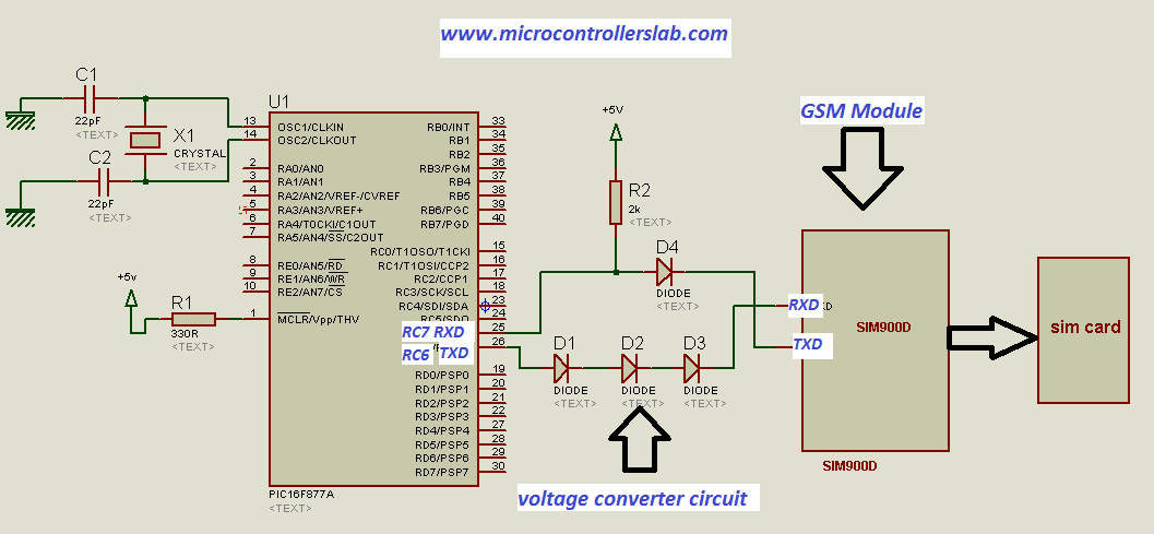
In the article GSM Module Interfacing with PIC Microcontroller, it is discussed that the RXD and TXD pins of the GSM module and PIC microcontroller should be connected with each other in reverse. This is because the GSM module receives the transmitted data from the PIC microcontroller, and similarly, the RXD pin of the PIC microcontroller receives the transmitted data from the TXD pin of the GSM module. This method of communication involves connecting the devices through a 2-wire serial communication to send data from one device to another.
Serial communication means sending data bit by bit. It is important to consider the baud rate while using serial communication. The baud rate is the number of bits transferred per second from one device to another. You should ensure that the baud rate is compatible between the two devices. Usually, the SIM900D GSM module supports a baud rate of 9600 with UART-type serial communication. UART stands for Universal Asynchronous Receiver and Transmitter. The PIC microcontroller has built-in hardware to implement UART serial communication between the PIC microcontroller and the GSM module. The SIM900D GSM module also supports UART serial communication. The circuit diagram is shown below.
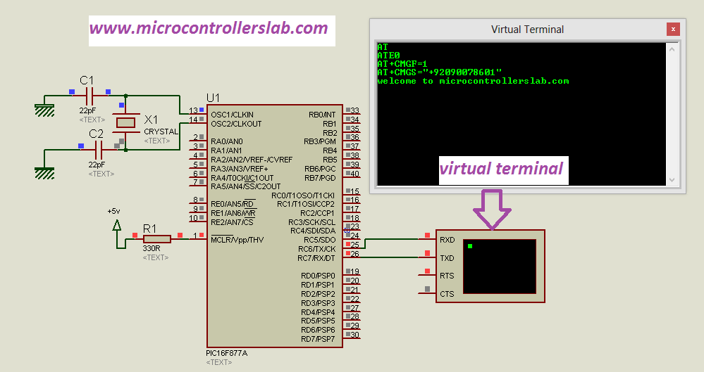
Because there is no GSM simulation model available in Proteus to simulate it. But you can check your virtual HyperTerminal available in Proteus to verify whether the microcontroller is transmitting data or not.
Note: If you are using a GSM module that has direct TX and RX pins exposed, you do not need external components. For that, you can simply connect TX and RX pins to the Rx and Tx pins of the PIC microcontroller, respectively.
MikroC Code
The code for this project is written in the MIKROC compiler. If you do not know how to use MikroC for Pic, you can refer to these tutorials:
- How to Use “MikroC PRO for PIC” to Program PIC Microcontrollers
- Pic microcontroller programming in c using Mikroc Pro for PIC
This code sends an SMS message using a GSM modem and Pic microcontroller through UART communication. It sets various AT commands to configure the modem and sends the desired message.
// Define AT commands and message
char AT[] = "AT";                       // To initialize mode
char noecho[] = "ATE0";                 // To stop echo
char mode_text[] = "AT+CMGF=1";         // to set text mode
char char_mode[] = "AT+CSCS=\"GSM\"";    // to set character mode
char param[] = "AT+CSMP=17,167,0,0";    // set the parameter of character
char mobile_no[] = "AT+CMGS=\"+92090078601\""; // use to set recipient number and message
char terminator = 0x1A;                 // character form of control + z terminator character
char mesg[] = "welcome to microcontrollerslab.com"; // message we want to send

// Function to write data serially
void send_to_modem(char *s)
{
    while (*s)
        UART1_WRITE(*s++);
    UART1_WRITE(0x0D); // Carriage return
}

// Function to send data without a carriage return
void send_to_modem1(char *s)
{
    while (*s)
        UART1_WRITE(*s++);
}

// Function to send SMS
void send_sms()
{
    send_to_modem1(mesg);
    delay_ms(100);
    uart1_write(terminator);
    delay_ms(1000);
}

void main()
{
    UART1_INIT(9600); // Initialize UART communication at 9600 baud

    send_to_modem(AT);        // Initialize modem with "AT" command
    delay_ms(2000);
    send_to_modem(noecho);    // Disable echo with "ATE0" command
    delay_ms(2000);
    send_to_modem(mode_text); // Set text mode with "AT+CMGF=1" command
    delay_ms(2000);
    send_to_modem(mobile_no); // Set recipient number with "AT+CMGS" command
    delay_ms(2000);
    send_sms();               // Send the SMS message
}
How Does Code Work?
Here is a step-by-step explanation of the code provided:
// Define AT commands and message
char AT[] = "AT";                       // To initialize mode
char noecho[] = "ATE0";                 // To stop echo
char mode_text[] = "AT+CMGF=1";         // to set text mode
char char_mode[] = "AT+CSCS=\"GSM\"";    // to set character mode
char param[] = "AT+CSMP=17,167,0,0";    // set the parameter of character
char mobile_no[] = "AT+CMGS=\"+92090078601\""; // use to set recipient number and message
char terminator = 0x1A;                 // character form of control + z terminator character
char mesg[] = "welcome to microcontrollerslab.com"; // message we want to send
Data Send Function
The above code block is used to define various AT commands, specific parameters, message content, and the recipient’s mobile number. Each command or data is stored in a character array for future use.
// Function to write data serially
void send_to_modem(char *s)
{
    while (*s)
        UART1_WRITE(*s++);
    UART1_WRITE(0x0D); // Carriage return
}
The code block above defines a function send_to_modem that takes a character pointer as an argument. This function writes the characters in the string pointed to by the character pointer *s to the modem serially using the UART1_WRITE function. It repeatedly writes each character until it reaches the null character ('\0'). Finally, it writes a carriage return character (0x0D) to indicate the end of the command.
// Function to send data without a carriage return
void send_to_modem1(char *s)
{
    while (*s)
        UART1_WRITE(*s++);
}
The above code block defines another function send_to_modem1 that performs the same task as the previous send_to_modem function, but without including the carriage return character. It simply writes each character of the string to the modem serially.
Send SMS Function
// Function to send SMS
void send_sms()
{
    send_to_modem1(mesg);
    delay_ms(100);
    uart1_write(terminator);
    delay_ms(1000);
}
The code block above defines send_sms function to send an SMS. It first calls the send_to_modem1 function to send the message content mesg to the modem serially without a carriage return. Then, a small delay of 100 milliseconds is introduced using delay_ms function. Next, it writes the termination character terminator to the modem using uart1_write function, which serves as the command to send the SMS. Another delay of 1000 milliseconds is added using delay_ms function.
Main Function
void main()
{
    UART1_INIT(9600); // Initialize UART communication at 9600 baud

    send_to_modem(AT);        // Initialize modem with "AT" command
    delay_ms(2000);
    send_to_modem(noecho);    // Disable echo with "ATE0" command
    delay_ms(2000);
    send_to_modem(mode_text); // Set text mode with "AT+CMGF=1" command
    delay_ms(2000);
    send_to_modem(mobile_no); // Set recipient number with "AT+CMGS" command
    delay_ms(2000);
    send_sms();               // Send the SMS message
}
The main function is the entry point of the program. It starts by initializing UART communication for the microcontroller with a baud rate of 9600 using UART1_INIT function.
Then, several functions are called in sequence:
- The
send_to_modemfunction initializes the modem by calling it with the “AT” command. It adds a delay of 2000 milliseconds (2 seconds) using thedelay_msfunction. - The
send_to_modemfunction disables echo from the modem by calling it with the “ATE0” command. Another delay of 2000 milliseconds is added. - The
send_to_modemfunction sets the modem to text mode by calling it with the “AT+CMGF=1” command. Again, a delay of 2000 milliseconds is added. - The
send_to_modemfunction sets the recipient of the SMS by calling it with the “AT+CMGS” command, followed by the recipient number. Another delay of 2000 milliseconds is added. - Finally, the
send_smsfunction is called to send the actual message.
This code demonstrates how to send an SMS using a GSM module and a PIC microcontroller. It uses UART serial communication to send AT commands to the modem and control the SMS sending process.
Demonstration
The diagram below shows a virtual terminal receiving data from a microcontroller. As I have already mentioned, you can use it for checking. However, it will only work when you interface the GSM module with your personal computer.
Conclusion
In conclusion, this article has provided a comprehensive guide on how to send SMS using a GSM module and PIC microcontroller. It has discussed the necessary hardware setup, the process of network registration, and the use of AT commands for SMS communication. The code provided demonstrates how to configure the modem and send an SMS message through UART communication. By following the steps outlined in this article, users can successfully implement SMS functionality in their projects. It is an active and practical solution for incorporating wireless communication capabilities into various applications.
Related content:
- Prepaid Energy Meter with GSM Modem using pic microcontroller
- Receive SMS GSM Module using pic microcontroller
- Sending Data from GSM module to a Web Server using Arduino
- GSM Based Home Automation project using Arduino
- Home security system using PIR sensor and GSM module
- wireless electronics notice board using gsm with code
- How to Answer Phone Call using GSM Module and Computer
- Wireless Temperature Sensor using GSM and Microcontroller
sir ;;;; do you know about a pic to wifi module to pc to vb interfacing?
Sir, Which appplication you have used to write and compile the code.
I have used Mikro c pro for pic by mikroE
I AM USIBG AURDINO TO SEND SMS THROUGH GSM MODULE BIT I HAVE LITTLE KNOWLEDGE ABOUT PROGRAMMING. SO PLZ HELP ME BY CODE AND FULL SUGESSION HOW CAN i send sms through gsm module to my desired valid mobile no.
i tried it on proteus but not getting the text on virtual terminal
what can i do for this
help plz
same things was happened to me,
try to use same clock size in codes and microcontroller (I was used 16MHz both in code building and in PIC16F877a ) and finally they displayed.
Sir,can u teach me how to coding pic16f877a for gsm to control the circuit..such as to turn off or turn on the led
sir i have need of matlab or proteous model of this project”
automatic load sharing of transformer by pic microcontroler”
can you send me it at 12el42@quest.edu.pk
hi i want contact with if you can my Email sintayehualem1@gmail.com
contact me at microcontrollerslabhub@gmail.com
Sir i need to make project on wireless notice using gsm using pic microcontroller… Sir will you put some light like what all components will i need to sumulate using proteus and some imp tips on it
hello! thank you for eplication (Y) I wonder if this program is for pic18f4550 ??
Hey! What would I have to change for this code to work on a 16f887?
Can I use a PIC18F45K22 microcontroler?
hey bilal….. i have problem in my c-code for sending sms using gsm 900… i have received only call not sms please help me for that i have used pic16f887 for my project…
thanks
I tried sending sms from my M590E GSM module and am getting nothing at the moment. The modem is interfacing with AT89S52 microController. please help me with a code to debug the program.
You have a diode in the RX of PIC and TX of your gsm module, so dont you think it should be facing the otherway as this will block any thing coming from gsm
don’t we need to declare the uart1_init () and uart1_write() functions?
Hi I am unable to get the ok messages in second virtual terminal what is the problem
Please, what’s COMPIN configuration?
compin configuration is same as what he did configuration video.
this is very important to me..
thanks..
very nice
Hi I’m trying to modify this code for use in MPLAB X – XC8. I keep getting an error message that says that the functions are being used in the incorrect format. Please tell me what changes I can make to use this code in XC8
Thanks
Sir, I need a circuit diagram and details for an Automatic booking of lpg gas (SMS) when cylinder volume gets low.Please help me Sir! Thanks in advance.
I think, D4 should be placed in otherway. Clarify please
Sir it work for pic18f4520 pic microcintroller
sir, it can work for gsm sim 800L?
thank you sir for your motivation but i need protuos soft ware please send me the code of your vidio and if you can the program of gsm based monitoring of generators fuel and batteries level in base station sites ,to my email address
The code is sending message repeatedly with A6 GSM module. How can I modify the code for calling thanks
you need to add a flag when you want to send a message. For example you can add a time after which you want to send sms
Please how do I add the time. Bellow is the code I wrote, I have also tried the one you posted but am still getting the same problem.
void main(){
UART1_init(9600); //Initiate baud rate to 9600
Delay_ms(2000);
UART1_Write_Text(“AT”);
Delay_ms(2000);
UART1_Write(0x0D) ; // mean (Enter)
Delay_ms(2000);
UART1_Write_Text(“ATE0”); // Please give your no where have to send sms
Delay_ms(2000);
UART1_Write(0x0D) ; // mean (Enter)
Delay_ms(2000);
UART1_Write_Text(“AT+CMGF=1”); // Please give your no where have to send sms
Delay_ms(2000);
UART1_Write(0x0D) ; // mean (Enter)
Delay_ms(2000); // Wait a bit after the AT+CMGF=1 command
UART1_Write_Text(“AT+CMGS=\”+2347032199427\””); //’AT+CMGS=
Delay_ms(2000);
UART1_Write(0x0D) ; // mean (Enter)
Delay_ms(2000);
UART1_Write_Text(“testing GSM module”); // State test value
Delay_ms(1000);
UART1_Write(0x1A); // Ctrl+Z
Delay_ms(2000);
}
please help me with a code to debug the program.
Use the one above with pic16f877a
is it possible to change the code and use sim800L instead? my guess was just to change in the code just the name because they work almost the same, but i don’t really know if it is just that. thank you
yes it can be used
Hello please I observed something, I used the code and I observed that the system send more than one message continuously. Please how can I prompt the code to send only one message and after sending it should not resend it again.
Tried this code in MikroC but it doesn’t work, it shows errors.
I have not found even a single code on internet that can be converted to hex and can be run from PIC16F877A.