Receive SMS gsm module using pic microcontroller, In this article, you will learn how to receive SMS using gsm module SIM900A and pic microcontroller. I have already posted many articles on SIM900 GSM and gsm module interfacing with pic microcontoller. Many users have asked me to post an article on how to receive SMS using gsm with pic microcontroller.
Recommended Components
The following components are used in this project or are helpful for building it with a PIC microcontroller.
| Component | How it’s used in this project | Buy on Amazon |
|---|---|---|
| PIC16F877A microcontroller | The 40-pin PIC MCU that runs this tutorial’s code. | Check Price |
| PICkit 5 programmer/debugger | Programs and debugs the PIC over the ICSP header. | Check Price |
| SIM900A GSM module | Receives the SMS and passes it to the PIC over UART. | Check Price |
| Breadboard | Solderless base for wiring the PIC and the project’s components. | Check Price |
| Jumper Wires | Make the connections between the MCU, components and power rails. | Check Price |
As an Amazon Associate we earn from qualifying purchases. Prices and availability are accurate as of the date/time indicated and are subject to change.
Prerequisites
First of all, to use gsm module like SIM900A, SIM900B or many other versions available in the market, you first should know how to use AT commands to communicate with the SIM900A module and MCU. Because the only way to interact with this module is through AT commands. Microcontroller sends specific AT commands to microcontroller and GSM module responds accordingly.
How to Recieve SMS with SIM900 Module?
For example, to send SMS using GSM module and pic microcontroller, the user has to use specific commands and similarly, we can make a call and answer phone call using this modem. So let’s start with AT commands which are used to receive SMS and how to read this SMS and send date to UART of pic microcontroller. Because all SIM900A modules work on UART serial communication protocol.
Following commands are used to receive SMS and initialize modem that whenever it receives SMS, send this to the UART pin of SIM900A. Whenever data will be available on the RX pin of Pic microcontroller, we receive this data and perform data analysis to get a message from that data. We interface SIM900 with PIC18F452 microcontroller through UART communication. Because the SIM900A module communicates through UART communication. This is a recommended reading:
UART Communication Module PIC Microcontroller
SIM900A AT Commands for Receiving SMS
First, we configure a GSM module to SMS receive mode. For that first send “AT” string and check response, if the response is “OK”. That means SIM900A is properly configured and working fine.
AT: It will check the gsm module either it will be connected with a microcontroller or not and responds with ‘OK’ if it is connected.
ART1_Write_Text("AT\r\n"); //send AT through UART functionSIM900A GSM modem, SMS service works in text mode or PDU mode. In text mode, we can recieve messages in text format and we also want to receive message in text format. Hence, we wil select text mode.
AT+CMGF command sets the gsm module to text mode or PDU mode. By setting AT+CMGF=1, sets the text mode. Because we want to receive data in text format so that we can handle it easily while extracting SMS from the string which gsm will send to Pic microcontroller. I will explain it in more detail in the latter part of this article.
UART1_Write_Text("AT+CMGF=1\r\n"); // sets the text-modeFinally, the last command that we are using is related to message reception and sending received messages on UART transmit pin of the SIM900A GSM modem.
During the initialization of the module , we send AT+CNMI=1,2,0,0,0 to the modem. This command force the gsm module to send “receive SMS” string on UART transmit pin of the GSM module and it will receive on RX pin of PIC microcontroller. Therefore, whenever SMS is received, Pic microcontroller can read it serially through the RX pin of UART.
UART1_Write_Text("AT+CNMI=1,2,0,0,0\r\n"); //activate message transfer to UART pin settingSo these are the only three commands which will be used to receive SMS and send this SMS to PIC18F452.
Circuit diagram to receive SMS using Pic microcontroller
So now let’s move to the circuit diagram. The circuit diagram to receive SMS is shown below. Connections between PIC18F452 and SIM900A remains the same in all cases either you are sending or receiving SMS. Make Connections according to this table:
| PIC18F452 | SIM900A |
|---|---|
| RX/RC7 | TX |
| TX/RC6 | RX |
Also connect 5 volts power supply to GSM module and ground connection for MCU and SIM900A Module should be common.
Note: GSM modules typically requires 2-3 Ampere current while sending or receiving message. Therefore, we recommend to use atleast three ampere adapter.

So this is a self-explanatory circuit diagram. You just have to connect the RX pin of gsm module with the TX/RC6 pin of PIC18F452 and TX pin of SIM900A with RX/RC7 pin of PIC microcontroller which is obvious that receiver of one is a transmitter of other and vice versa. But make sure to connect the power supply with gsm module which can supply peak current of 2A because while sending and receiving SMS, it will take current in the order of two amperes.
Interfacing with Other Pic Microcontrollers
We have used a pic18f452 microcontroller while making this tutorial, but you can use any microcontroller you want and it depends on your application and selection of microcontroller depends on your microcontroller-based project.
How to use in Proteus
Even if you don’t have a Pic microcontroller and you only have a SIM900A module. You can still learn to program with GSM module using proteus simulation software. You know what we can connect gsm module to COM connector in proteus so it means we can test our code by connect gsm module with computer or laptop and use it send data to proteus. In short, we can test our code without making actual hardware. But I recommend you test it on hardware.
Receive sms on computer or laptop
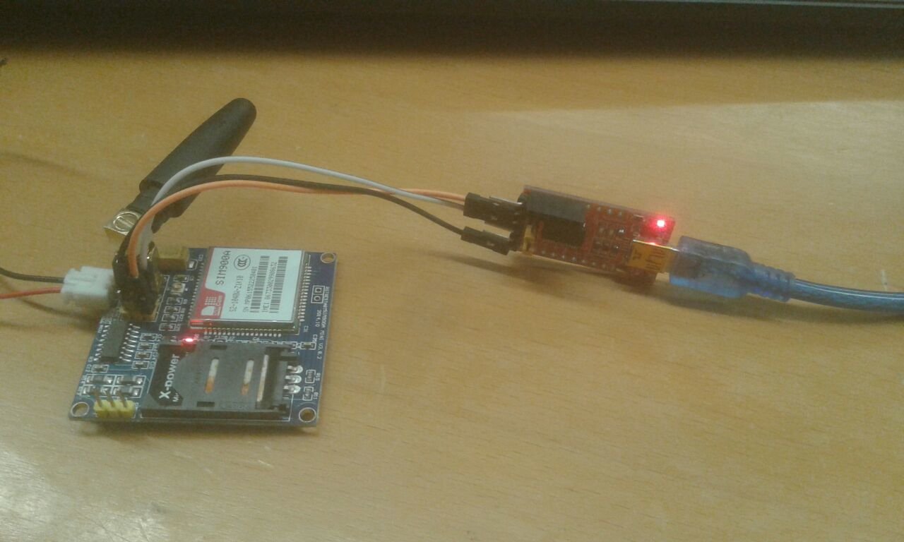
So, first of all, let’s check, how the received message string will look like when the pic microcontroller receives it. For this purpose, we have to connect the SIM900A module with a computer or laptop. We have connected it with our laptop using USB to TTL converter as shown in the figure below:
If you don’t know what is USB to serial converter and How to use USB to Serial converter, read this tutorial:
How to use USB-TTL Converter Module
First, we initialize the SIM900A modem by sending the above-mentioned three commands through the UART terminal and the modem responded with an “OK” response. After that, we have sent the sms from the mobile number to sim in the gsm module. We used serial terminal proteus to receive sms as shown in the figure below:

Received SMS String Format
As you can see from the above diagram that the string received from gsm consists of +CMT at the start of the string and it also includes sender mobile number, date and message at the end which is “microcontrollerslab.com” in this case. Therefore, we need to extract SMS string from this received string to use it for a useful purposes.
For example, you want to use it to control home devices by sending a specific string to SIM900A. Therefore, you need to extract a real message from the string.
How to extract SMS from Received String
Follow following step to extract message from this string:
- Send AT commands to from microcontroller to GSM as mentioned above to check it and initialize to send receive a message to UART when it receives SMS from any number.
- After that initialize the UART module of the pic microcontroller and start receiving string from SIM900A transmit pin and store it in a character type variable.
- After that, you should use string parsing to get only SMS string form whole received string from the gsm module.
How to receive SMS using gsm and pic microcontroller
As mentioned above, you have to use the UART module to receive SMS available on UART pins of the SIM900A modem. you should use UART as interrupt so that whenever data available on TX and RX pin, microcontroller stops normal execution and goes to interrupt service routine to receive SMS string. I have connected the gsm module to proteus and receiving SMS.

Video lecture on how to receive sm using gsm
Check the video results shown below:
MikroC Code
This code is written using MikroC for Pic compiler. Create a new project with MikroC compiler by selecting PIC16F877A microcontroller and set frequency to 8MHz. If you don’t know how create new project in mikroC, we suggest you read this post:
char IncData;
int x =  0;

char RcvdMsg[60] = "";
int RcvdCheck = 0;
int RcvdConf = 0;
int index = 0;
int RcvdEnd = 0;
char MsgMob[15];
char MsgTxt[10];
int MsgLength = 0;

void RecSMS();
void ClearBuffers();
void Config();

void main() {
  TRISD=0X00;
  PORTD=0X00;
  TRISC.F7 = 1;
  UART1_Init(9600);               // Initialize UART module at 9600 bps
  Delay_ms(100);                  // Wait for UART module to stabilize
  Config();

  while(1)
  {      while(!UART1_Data_Ready());
          if (UART1_Data_Ready())
        {
          IncData = UART1_Read();
          //UART1_Write_Text(IncData);
          if(IncData == '+'){RcvdCheck = 1;}
          if((IncData == 'C') && (RcvdCheck == 1)){RcvdCheck = 2;}
          if((IncData == 'M') && (RcvdCheck == 2)){RcvdCheck = 3;}
          if((IncData == 'T') && (RcvdCheck == 3)){RcvdCheck = 4;}
          if(RcvdCheck == 4){index = 0;RcvdConf = 1; RcvdCheck = 0;}

          if(RcvdConf == 1)
          {
              if(IncData == '\n'){RcvdEnd++;}
              if(RcvdEnd == 3){RcvdEnd = 0;}
              RcvdMsg[index] = IncData;

              index++;
              if(RcvdEnd == 2){RcvdConf = 0;MsgLength = index-2;index = 0;}
              if(RcvdConf == 0)
              {
                  //PortD.F3 = 1;
                  UART1_Write_Text("Mobile Number is: ");
                  for(x = 4;x < 17;x++)
                  {
                      MsgMob[x-4] = RcvdMsg[x];
                      UART1_Write(MsgMob[x-4]);
                  }
                 UART1_Write(0x0D);
                 UART1_Write_Text("Message Text: ");
                  for(x = 46;x < MsgLength;x++)
                  {
                      MsgTxt[x-46] = RcvdMsg[x];
                      UART1_Write(MsgTxt[x-46]);
                  }
                  if(MsgTxt[0] == 'A'){ PortD.F0 = 1;}//L1ON();}
                  if(MsgTxt[0] == 'B'){ PortD.F0 = 0;}//L1OF();}
                  if(MsgTxt[0] == 'C'){ PortD.F1 = 1;}//L2ON();}
                  if(MsgTxt[0] == 'D'){ PortD.F1 = 0;}//L2OF();}
                  if(MsgTxt[0] == 'E'){ PortD.F2 = 1;}//L3ON();}
                  if(MsgTxt[0] == 'F'){ PortD.F2 = 0;}//L3OF();}
                  if(MsgTxt[0] == 'G'){ PortD.F3 = 1;}//L4ON();}
                  if(MsgTxt[0] == 'H'){ PortD.F3 = 0;}//L4OF();}
                  ClearBuffers();
              }
          }
     }
  }

}


void ClearBuffers()
{
    strcpy(RcvdMsg,"");
    RcvdCheck = 0;
    RcvdConf = 0;
    index = 0;
    RcvdEnd = 0;
    strcpy(MsgMob,"");
    strcpy(MsgTxt,"");
    MsgLength = 0;
}

void Config()
{
 Delay_ms(2000);
    UART1_Write_Text("ATE0\r\n");
    Delay_ms(1000);
    UART1_Write_Text("AT\r\n");
    Delay_ms(1000);
    UART1_Write_Text("AT+CMGF=1\r\n");
    Delay_ms(1000);
    UART1_Write_Text("AT+CNMI=1,2,0,0,0\r\n");
    Delay_ms(1000);
}
MPLAB XC8 Compiler Code
This code is for MPLAB XC8 Compiler. If you don’t know how to use MPLAB and XC8 compiler, you can read this complete in-depth guide:
After creating a new project, set configuration bits by generating configuration bit file with MPLAB XC8. While generating this file, select the HS crystal option and leave the remaining setting as to default settings.
#define _XTAL_FREQ 8000000
#include <xc.h>
#include<pic18f452.h>
#include <stdio.h>
#include <string.h>
#include <stdlib.h>

char IncData;
int x =  0;

char RcvdMsg[60] = "";
int RcvdCheck = 0;
int RcvdConf = 0;
int index = 0;
int RcvdEnd = 0;
char MsgMob[15];
char MsgTxt[10];
int MsgLength = 0;
void ClearBuffers();
void Config();
char UART_Init(const long int baudrate)
{
	unsigned int x;
	x = (_XTAL_FREQ - baudrate*64)/(baudrate*64);
	if(x>255)
	{
		x = (_XTAL_FREQ - baudrate*16)/(baudrate*16);
		BRGH = 1;
	}
	if(x<256)
	{
	  SPBRG = x;
	  SYNC = 0;
	  SPEN = 1;
          TRISC7 = 1;
          TRISC6 = 1;
          CREN = 1;
          TXEN = 1;
	  return 1;
	}
	return 0;
}

char UART_TX_Empty()
{
  return TRMT;
}

char UART_Data_Ready()
{
   return RCIF;
}
char UART_Read()
{

  while(!RCIF);
  return RCREG;
}

void UART_Read_Text(char *Output, unsigned int length)
{
	unsigned int i;
	for(int i=0;i<length;i++)
		Output[i] = UART_Read();
}

void UART_Write(char data)
{
  while(!TRMT);
  TXREG = data;
}

void UART_Write_Text(char *text)
{
  int i;
  for(i=0;text[i]!='\0';i++)
	  UART_Write(text[i]);
}
void MSdelay(unsigned int val)
{
     unsigned int i,j;
        for(i=0;i<val;i++)
            for(j=0;j<165;j++);      /*This count Provide delay of 1 ms for 8MHz Frequency */
 }


void main() {
    TRISC6 = 0; // TX Pin set as output
    TRISC7 = 1; // RX Pin set as input
  TRISD=0X00;
  PORTD=0X00;
  UART_Init(9600);
// _delay_ms(100);
                 // Wait for UART module to stabilize
  Config();

  while(1)
  {

          if (UART_Data_Ready())
        {
          IncData = UART_Read();
          RD5=1;

          if(IncData == '+'){RcvdCheck = 1;}
          if((IncData == 'C') && (RcvdCheck == 1)){RcvdCheck = 2;}
          if((IncData == 'M') && (RcvdCheck == 2)){RcvdCheck = 3;}
          if((IncData == 'T') && (RcvdCheck == 3)){RcvdCheck = 4;}
          if(RcvdCheck == 4){index = 0;RcvdConf = 1; RcvdCheck = 0;}

          if(RcvdConf == 1)
          {
              if(IncData == '\n'){RcvdEnd++;}
              if(RcvdEnd == 3){RcvdEnd = 0;}
              RcvdMsg[index] = IncData;

              index++;
              if(RcvdEnd == 2){RcvdConf = 0;MsgLength = index-2;index = 0;}
              if(RcvdConf == 0)
              {
                  //PortD.F3 = 1;

                  for(x = 4;x < 17;x++)
                  {
                      MsgMob[x-4] = RcvdMsg[x];

                  }

                  for(x = 46;x < MsgLength;x++)
                  {
                      MsgTxt[x-46] = RcvdMsg[x];

                  }
                  if(MsgTxt[0] == 'A'){ RD0 = 1;}//L1ON();}
                  if(MsgTxt[0] == 'B'){ RD0 = 0;}//L1OF();}
                  if(MsgTxt[0] == 'C'){ RD1 = 1;}//L2ON();}
                  if(MsgTxt[0] == 'D'){ RD1 = 0;}//L2OF();}
                  if(MsgTxt[0] == 'E'){ RD2 = 1;}//L3ON();}
                  if(MsgTxt[0] == 'F'){ RD2 = 0;}//L3OF();}
                  if(MsgTxt[0] == 'G'){ RD3 = 1;}//L4ON();}
                  if(MsgTxt[0] == 'H'){RD3= 0;}//L4OF();}
                  if(MsgTxt[0] == 'I'){ RD4 = 1;}//L4ON();}
                  if(MsgTxt[0] == 'J'){RD4= 0;}//L4OF();}
                  ClearBuffers();
   }
          }
     }
  }

}
void ClearBuffers()
{
    strcpy(RcvdMsg,"");
    RcvdCheck = 0;
    RcvdConf = 0;
    index = 0;
    RcvdEnd = 0;
    strcpy(MsgMob,"");
    strcpy(MsgTxt,"");
    MsgLength = 0;
}

void Config()
{

}
In summary, this is all about how to receive SMS from SIM900A and send it to computer or laptop.
- We also learned how to receive this SMS using PIC microcontroller and how to extract real SMS from gsm string.
- Further, how to analyze received message using proteus virtual terminal
- In the end, we provided codes in MikroC and MPLAB XC8 Compiler.
sir i want gsm and gps code.
even i need the code. plz provide with the code like the previous module
How do you parse the strings mr. Bilal? I think that you used the “strtok” command in mikroc, is that correct?
Good afternoon. I am reading your articles from Mexico.
can you plz send me the code for how to read a text message using 8051
can u please send me the code i need it to communicate between gps gsm pic18f2550, here is my email: othmane.knine@ump.ac.ma