Hi everyone, In this tutorial I will show you how to interface RGB LED with pic microcontroller RGB led is basically a multiple color LED and as you already know LED stands for light emitting diode. If you already know how to interface light emitting diode with pic microcontroller. This tutorial will be very easy for you because the process of interfacing RGB LED with microcontroller is same as interfacing of single LED with pic microcontroller. So let’s start with basic introduction of RGB LED. I am using PIC16F877A microcontroller in this tutorial. 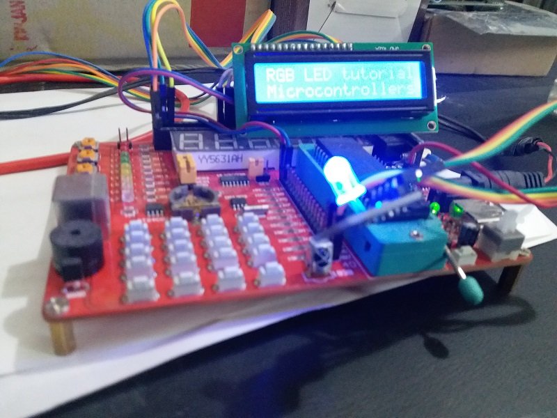
What is RGB LED and how RGB LED work?
RGB LED basically a same as light emitting diode. But it emits red, green and blue lights. It consists of three leds and they are a combination red, green and blue. so whenever voltage applied to red terminal ,red light will emit and similarly when voltage applied to Green and blue terminal green and blue lights respectively. As I mentioned earlier, It consists of three LED’s
- 1 x RED LED
- 1 x Green LED
- 1 X Blue LED
There are two type of RGB light emitting diodes are available in market.

- Common Anode type: In common Anode type, Anode is common for all three Light emitting diodes and Anode of all the light emitting diodes connects with positive power supply. Other terminals connects with microcontroller and we turn on and off these terminals according to which LED we want to turn on or turn off.
- Common Cathode type: In common Cathode type, Cathode of all three light emitting diodes are common and common cathode terminal is connected with ground of power supply and other terminal of each power LED is connected with pic microcontroller according to which LED we want to turn on or turn off.
Picture of both common anode and common cathode types RGB LED is shown below: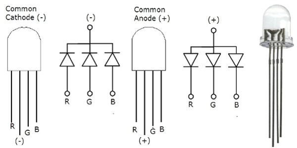
RGB LED and its pinout is shown below. I am using common cathode types RGB LED in this tutorial. Detail of each pin is also given below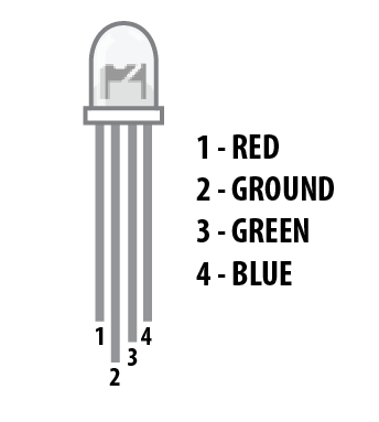
- Pin number 1 is red color select pin and you should connect it with microcontroller
- Pin number 2 is ground pin for common cathode type and 5 volt Vdd pin for common anode type.
- Pin number 3 is Blue color select pin and you should also connect it with output pin of pic microcontroller
- Pin number 4 is a also a Green color select pin and it is also connect with digital output pin of pic microcontroller.
So this was a introduction of RGD LED and its types. So now let’s see how to interface RGB LED with microcontroller.
RGB LED interfacing with PIC microcontroller
Before connecting it with pic microcontroller, we need to connect a current limiting resistor with each color selecting pin. Because we need to limit current flow to each pin. Otherwise it may get damaged. It is shown below.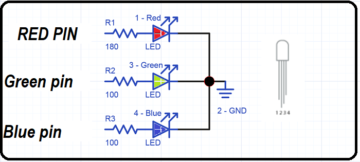
Complete circuit diagram of RGB LED interfacing with pic16F877A microcontroller is shown below. RGB light emitting diode is connected with PORTD of PIC16F877A microcontroller. Pin number 1 is connected with PORTD pin number zero , pin 3 is connected with pin number one of PORTD and similarly, pin number four is connected with pin number 2 of PORTD. Common terminal is connected with ground.

Now we need to write code for this tutorial. To write code, first we all we need to initialize PORTD of pic16F877A microcontroller as a output. After initializing it as a output,we will make every pin logic high for one second sequentially. If you don’t know how to use input output ports of pic microcontroller, I recommend you to read following articles:
- How to program pic microcontroller
- Introduction to Mikro c for pic
- How to upload code to pic microcontroller
- How to use input output ports of pic microcontroller
Code of RGB LED interfacing with pic microcontroller
Code for this tutorial is written using Mikro c for pic compiler. I have also used a LCD in this tutorial. But this is optional. I am just displaying a text on LCD ” RDG LED tutorial” . SO do not confuse with it.
// LCD module connections
 sbit LCD_RS at RD2_bit;
 sbit LCD_EN at RD3_bit;
 sbit LCD_D4 at RD4_bit;
 sbit LCD_D5 at RD5_bit;
 sbit LCD_D6 at RD6_bit;
 sbit LCD_D7 at RD7_bit;
 sbit LCD_RS_Direction at TRISD2_bit;
 sbit LCD_EN_Direction at TRISD3_bit;
 sbit LCD_D4_Direction at TRISD4_bit;
 sbit LCD_D5_Direction at TRISD5_bit;
 sbit LCD_D6_Direction at TRISD6_bit;
 sbit LCD_D7_Direction at TRISD7_bit;
 // End LCD module connections

void main() {
 Lcd_Init();
 Lcd_Cmd(_LCD_CURSOR_OFF); // cursor off
 Lcd_Cmd(_LCD_CLEAR); // clear LCD
 Lcd_out(1 ,1, "RGB LED tutorial");
 Lcd_out(2 ,1, "Microcontrollers LAB");
 TRISD=0X00;
 PORTD=0X00;
 while(1)
 {
 PORTD.B0=1;
 PORTD.B1=0;
 PORTD.B2=0 ;
 delay_ms(1000);
 PORTD.B0=0;
 PORTD.B1=1;
 PORTD.B2=0 ;
 delay_ms(1000);
 PORTD.B0=0;
 PORTD.B1=0;
 PORTD.B2=1 ;
 delay_ms(1000);
 }
}
BU RGB UYGULAMASINI PWM İLE NASIL YAPABİLİRİM PWM İLE MOSFET SÜRÜP MOSFET İLE LEDLERİ SÜRMEK İSTİYORUM