 In this tutorial, I will show you how to interface DHT11 humidity sensor with pic microcontroller and how to measure temperature and humidity with DHT11 sensor. DHT11 is a low cost and accurate sensor. It can be easily interfaced with pic microcontroller by using only one input/output pin. In this tutorial, first we will collect temperature and humidity data from DHT11 sensor and after that we will display this data in 16 x 2 liquid crystal display. You may also like to check an article on how to interface DHT11 sensor with Arduino to measure humidity and temperature. So let’s first understand the working and other features of DHT11 humidity and temperature sensor.
[alert-note]>>Read DHT11 interfacing with Arduino[/alert-note]
Recommended Components
The following components are used in this project or are helpful for building it with a PIC microcontroller.
| Component | How it’s used in this project | Buy on Amazon |
|---|---|---|
| PIC16F877A microcontroller | Sends the start signal, decodes the DHT11 40-bit data and shows temperature/humidity on the LCD. | Check Price |
| PICkit 5 programmer/debugger | Uploads the compiled hex file into the PIC16F877A and debugs the circuit. | Check Price |
| DHT11 sensor | Measures temperature and humidity and sends them to the PIC over a single-wire digital interface. | Check Price |
| Breadboard | Holds the PIC, DHT11 sensor and pull-up resistor for solderless prototyping. | Check Price |
| Jumper Wires | Connect the DHT11 data pin (with a 5kΩ pull-up), VCC and GND to the PIC. | Check Price |
As an Amazon Associate we earn from qualifying purchases. Prices and availability are accurate as of the date/time indicated and are subject to change.
Introduction to DHT11 humidity and temperature sensor
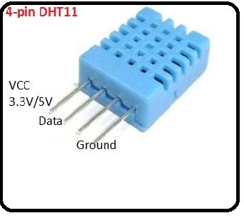
DHT11 sensor has four pins as shown below. You need to make the connections of sensor according to followings:
- Vcc should be connected with 5 volt power supply
- Data pin should be connected with input pin of microcontroller through a 5k OHM push pull resistor.
- NC pin is not used pin. So there is no need to connect it with anything
- Ground pin should be connected with ground terminal of power supply.

It can measure temperature with in a accuracy of 2% and humidity with in accuracy of 5%. It can be connected with microcontroller with a maximum wire of 20 meter range. If you want to increase the distance , you have to choose push pull resistor between microcontroller and data pin of DHT11 sensor accordingly. I also recommend you to add 100nF capacitor between ground and Vcc pin to voltage fluctuations. DHT11 sensor consists of a resistive type humidity measurement component and NTC type temperature measurement component. It provides humidity and temperature value on highly calibrated digital output signal. So we need to measure this digital output signal with the help of microcontroller to measure temperature and humidity. So it has a single wire serial interface, we will use this interface to connect DHT11 sensor with pic microcontroller.
Working of DHT11 sensor
As mentioned earlier DHT11 sensor provided data in the form of pulses. These pulses basically consists of pulse trains which contains temperature and humidity data. we need to measure these pulses train and find a way to extract data from these pulses. To get these pulses from sensor, we first need to send start signal in the form of pulse from microcontroller to DHT11 sensor. After that DHT11 sensor sends data to microcontroller in the form of pulses. It takes around 45ms to complete this process.
These basically are basically a 40 bit data which contains temperature and humidity. DHT11 will not give any response without the start signal and will remain in low power consumption mode or in sleep mode. So this how we will receive data from DHT11 humidity and temperature sensor. User can send the start signal after specified time and whenever user needs data from sensor.
DHT11 sensor interfacing with pic microcontroller
Circuit diagram of DHT11 sensor interfacing with pic microcontroller is shown below.
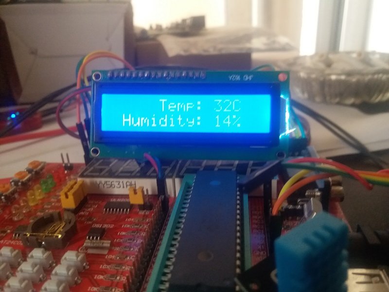
I am using PIC16F877A microcontroller in this tutorial. We have connected this sensor with PORTD pin number zero of PIC16F877A microcontroller. LCD is connected with PORTC of PIC16F877A microcontroller. So let’s see its working . First of all pic16f877a microcontroller send the high signal to DHT11 sensor and wait for the response of DHT11 for about 20-25us. Once DHT11 detects a start signals, it sends a low signal of period 80us to pic microcontroller. After that DHT11 makes it ready to send 40 bit data to pic microcontroller. Pic microcontroller decodes this 40 bit data and separates the value of temperature and humidity.
These values of temperaure and humidity stored in strings and after that these strings are displayed on LCD. if you don’t know how to interface LCD with pic16f877a microcontroller and how to use input output ports of pic microcontroller, you can read these articles:
- LCD interfacing with PIC16F877A microcontroller
- How to use input output ports of pic microcontroller
- How to scroll text on LCD
- How to display custom characters on LCD
Code for DHT11 sensor interfacing with pic microcontroller
Code for DHT11 humidity and temperature sensor is given below. Code is written using Mikro C for pic compiler. you can check the getting started article on mikro c for pic here:- Getting started with Mikro c for pic writing your first program
- PIC microcontroller programming in Mikro c for pic
// LCD module connections
 sbit LCD_RS at RD2_bit;
 sbit LCD_EN at RD3_bit;
 sbit LCD_D4 at RD4_bit;
 sbit LCD_D5 at RD5_bit;
 sbit LCD_D6 at RD6_bit;
 sbit LCD_D7 at RD7_bit;
 sbit LCD_RS_Direction at TRISD2_bit;
 sbit LCD_EN_Direction at TRISD3_bit;
 sbit LCD_D4_Direction at TRISD4_bit;
 sbit LCD_D5_Direction at TRISD5_bit;
 sbit LCD_D6_Direction at TRISD6_bit;
 sbit LCD_D7_Direction at TRISD7_bit;
 // End LCD module connections
 unsigned char Check, T_byte1, T_byte2,
 RH_byte1, RH_byte2, Ch ;
 unsigned Temp, RH, Sum ;
void StartSignal(){
 TRISD.B0 = 0; //Configure RD0 as output
 PORTD.B0 = 0; //RD0 sends 0 to the sensor
 delay_ms(18);
 PORTD.B0 = 1; //RD0 sends 1 to the sensor
 delay_us(30);
 TRISD.B0 = 1; //Configure RD0 as input
 }
 //////////////////////////////
 void CheckResponse(){
 Check = 0;
 delay_us(40);
 if (PORTD.B0 == 0){
 delay_us(80);
 if (PORTD.B0 == 1) Check = 1; delay_us(40);}
 }
 //////////////////////////////
 char ReadData(){
 char i, j;
 for(j = 0; j < 8; j++){
 while(!PORTD.B0); //Wait until PORTD.F0 goes HIGH
 delay_us(30);
 if(PORTD.B0 == 0)
 i&= ~(1<<(7 - j)); //Clear bit (7-b)
 else {i|= (1 << (7 - j)); //Set bit (7-b)
 while(PORTD.B0);} //Wait until PORTD.F0 goes LOW
 }
 return i;
 }
 //////////////////////////////
void main() {
 TRISD.F1 = 0;
 Lcd_Init();
 Lcd_Cmd(_LCD_CURSOR_OFF); // cursor off
 Lcd_Cmd(_LCD_CLEAR); // clear LCD
 while(1){
 StartSignal();
 CheckResponse();
 if(Check == 1){
 RH_byte1 = ReadData();
 RH_byte2 = ReadData();
 T_byte1 = ReadData();
 T_byte2 = ReadData();
 Sum = ReadData();
 if(Sum == ((RH_byte1+RH_byte2+T_byte1+T_byte2) & 0XFF)){
 Temp = T_byte1;
 RH = RH_byte1;
 Lcd_Out(1, 6, "Temp: C");
 Lcd_Out(2, 2, "Humidity: %");
 LCD_Chr(1, 12, 48 + ((Temp / 10) % 10));
 LCD_Chr(1, 13, 48 + (Temp % 10));
 LCD_Chr(2, 12, 48 + ((RH / 10) % 10));
 LCD_Chr(2, 13, 48 + (RH % 10));
 }
 else{
 Lcd_Cmd(_LCD_CURSOR_OFF); // cursor off
 Lcd_Cmd(_LCD_CLEAR); // clear LCD
 Lcd_Out(1, 1, "Check sum error");}
 }
 else {
 Lcd_Out(1, 3, "No response");
 Lcd_Out(2, 1, "from the sensor");
 }
 delay_ms(1000);
 }
}
program is no error in mikiro compiler.but, run in proteus, lcd display no response from the sensor.plz,Sir.BILA,Let me know HOW TO SOLVE this.
Thanks sir for the tutorial. I wrote the code on my mikro. C. The code refuse to build indicating lots of errors. From the void main, char ReadData and more. Please how do I rectify this errors.
which compiler you are using?
Sir I wrote the code on MicroC. But I got several errors in the first line itself . i.e in the initialisation of sbit.
Error is like ‘;’ expected in LCD_RS .
Please help me out sir
you didn’t copied code correctly.
“Logic contention(s) detected on net #00013.”
Proteus error message about the data pin of the DHT11 sensor.
Please help.
please why are we adding 48 here??
LCD_Chr(1, 12, 48 + ((Temp / 10) % 10));
and please how can I get the real temperature and humidity and put it into an int to compare it .
Thanks for help
What is the protocol between pic and DT711 ? kindly help to tech me.