Digital Barometer using PIC microcontroller: In this tutorial, you will learn how to interface the MPX4115A pressure sensor with the PIC18F46K22 microcontroller. How to use the MPX4115A pressure sensor to design a digital barometer? What are the features of the MPX4115A pressure sensor? How does the MPX4115A pressure sensor work? How to measure the output voltage of the MPX4115A pressure sensor with the help of the PIC18F46K22 PIC microcontroller and convert this measured voltage into pressure and display the measured pressure value on a liquid crystal display? Now let’s start with a basic introduction and working of the MPX4115A pressure sensor, which is necessary to understand.
Before interfacing this pressure sensor with the PIC microcontroller, we should know how this sensor works and what is the output of this sensor? You may also like to check these sensor interfacing tutorials with the PIC microcontroller.
- temperature sensor interfacing with pic microcontroller
- heart beat sensor
- humidity sensor
- Light sensor
- AC current sensor
- AC voltage sensor
Recommended Components
The following components are used in this project or are helpful for building it with a PIC microcontroller.
| Component | How it’s used in this project | Buy on Amazon |
|---|---|---|
| PIC18F46K22 microcontroller | The 8-bit PIC MCU that runs the firmware and handles the ADC readings in this project. | Check Price |
| PICkit 5 programmer/debugger | Programs and debugs the PIC by flashing the compiled HEX file to the chip. | Check Price |
| MPX4115A pressure sensor | The analog absolute-pressure sensor whose output voltage is measured by the ADC. | Check Price |
| Breadboard | Solderless board for building and prototyping the circuit without soldering. | Check Price |
| Jumper Wires | Male-to-male jumper leads for wiring the components on the breadboard. | Check Price |
As an Amazon Associate we earn from qualifying purchases. Prices and availability are accurate as of the date/time indicated and are subject to change.
MPX4115A Pressure Sensor Introduction
MPX4115A pressure sensor is an integrated on-chip pressure sensor. It consists of a piezo resistive transducer which converts pressure into DC voltage. It can measure pressure from 15 kilopascals to 115 kilopascals. The output of the sensor ranges from 0.2 volts to 4.8 volts, depending on the pressure applied to the sensor.

Features
The following are the main features of this sensor:
- 1.5% maximum reading error over a wide range of temperature
- It is suitable for digital systems, embedded systems and microcontroller based projects
- It comes with a surface mount package.
Followings are the main applications of this sensor:
- Automotive industry
- engine control
- weather stations
- And many others
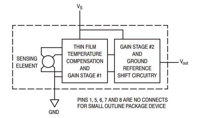
The internal block diagram of the MPX4115A pressure sensor is shown below. It has three pins: +5 volt input pin, ground pin, and output pin. We measure the output voltage from this pin and convert it back into pressure using the formula given in the datasheet. Providing pressure to a sensing element, it is a very useful pressure sensor for designing a microcontroller-based barometer.
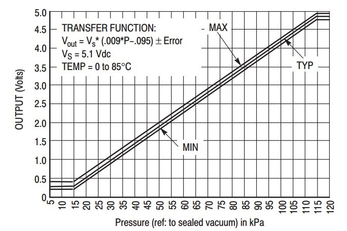
The graph below shows the relationship between the output voltage and input pressure. It can easily be observed that both have a somewhat linear relationship with each other, and the formula for voltage to pressure conversion is also given in the graph.
So, according to the graph above, the minimum pressure we can measure with this sensor is 15 kPa and the maximum is 115 kPa. Below 15 kPa, the output voltage of the sensor is zero, and above 115 kPa, the output voltage remains constant. We can easily design a digital barometer with the help of this pressure sensor because we already know how to measure voltage using the PIC18F46K22 microcontroller. By using the conversion formula provided above, we can easily convert the voltage into pressure. The formula below shows the relationship between the output voltage of the sensor and the input pressure.
Vout = Vs x ((0.009 x P) – 0.095) ± Error
MPX4115A pressure sensor interfacing with PIC microcontroller
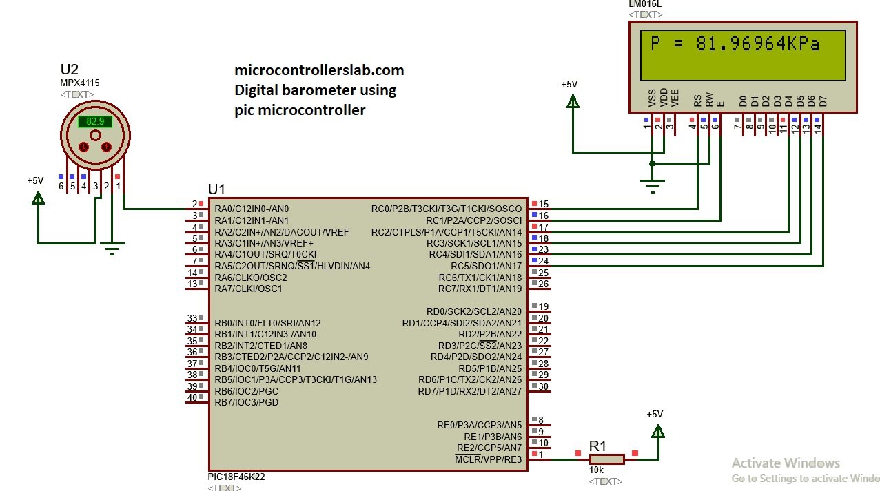
In this project, we are designing a digital barometer using the PIC18F46K22 microcontroller. Now let’s see how to connect the MPX4115A pressure sensor with the PIC microcontroller. To interface this sensor with the PIC microcontroller, we just need to connect the output pin of the MPX4115A pressure sensor with the analog input pin of the PIC microcontroller, as shown below. We have connected analog pin zero of the PIC18F46K22 with the output pin of the barometer sensor. We have also connected an LCD with the PIC18F46K22 microcontroller to display the measured value of pressure. If you don’t know how to interface an LCD with the PIC microcontroller, check out this LCD interfacing with PIC16F877A microcontroller article.
Code
The code for this project is written in the MIKROC compiler and 8Mhz crystal is used in this project. If you do not know how to use MikroC for Pic, you can refer to these tutorials:
- How to Use “MikroC PRO for PIC” to Program PIC Microcontrollers
- Pic microcontroller programming in c using Mikroc Pro for PIC
The main functionality of this code is to measure pressure using an ADC of a PIC microcontroller. It initializes the microcontroller, configures the analog-to-digital converter (ADC) to read the sensor’s voltage, performs calculations to convert the voltage into pressure, and continuously displays the pressure reading on an LCD screen. The program runs in an infinite loop, ensuring that the pressure reading is continually updated and displayed on the LCD.
// LCD module connections
sbit LCD_RS at LATC0_bit;        // Define LCD_RS pin at LATC0
sbit LCD_EN at LATC1_bit;        // Define LCD_EN pin at LATC1
sbit LCD_D4 at LATC2_bit;        // Define LCD_D4 pin at LATC2
sbit LCD_D5 at LATC3_bit;        // Define LCD_D5 pin at LATC3
sbit LCD_D6 at LATC4_bit;        // Define LCD_D6 pin at LATC4
sbit LCD_D7 at LATC5_bit;        // Define LCD_D7 pin at LATC5

sbit LCD_RS_Direction at TRISC0_bit;    // Define LCD_RS pin direction
sbit LCD_EN_Direction at TRISC1_bit;    // Define LCD_EN pin direction
sbit LCD_D4_Direction at TRISC2_bit;    // Define LCD_D4 pin direction
sbit LCD_D5_Direction at TRISC3_bit;    // Define LCD_D5 pin direction
sbit LCD_D6_Direction at TRISC4_bit;    // Define LCD_D6 pin direction
sbit LCD_D7_Direction at TRISC5_bit;    // Define LCD_D7 pin direction
// End LCD module connections

unsigned int ADCResult = 0;        // Variable to store ADC result
float pressure;                    // Variable to store pressure reading
unsigned char txt[15];            // Array to store text for display

void main() {
    OSCCON = 0x66;                 // Configure to use 8MHz internal oscillator.
    ANSELC = 0X00;                 // Configure PORTC pins as digital
    ANSELA = 0XFF;                 // Configure PORTA pins as analog
    TRISA.RA0 = 1;                 // Configure RA0 pin as input

    ADC_Init();                    // Initialize ADC module

    Lcd_Init();                    // Initialize LCD module
    Lcd_Cmd(_LCD_CLEAR);           // Clear LCD display
    Lcd_Cmd(_LCD_CURSOR_OFF);      // Turn off LCD cursor

    Lcd_Out(1, 1, "microcontrollers"); // Display "microcontrollers" on line 1
    Lcd_Out(2, 1, "lab.com");         // Display "lab.com" on line 2
    Delay_ms(2000);                // Delay for 2 seconds
    Lcd_Cmd(_LCD_CLEAR);           // Clear LCD display

    do {
        ADCResult = ADC_Read(0);   // Read ADC channel 0
        pressure = (ADCResult * 5.0) / 1023; // Calculate pressure
        pressure = (pressure + 0.475) / 0.0475; // Adjust pressure value
        FloatToStr(pressure, txt); // Convert pressure to text
        Lcd_Out(1, 1, "P = ");      // Display "P = " on line 1
        Lcd_Out_Cp(txt);            // Display pressure reading
        Lcd_Out_Cp("KPa");          // Display units (KPa)

    } while (1); // Infinite loop

}
How Does Code Work?
Certainly! Here’s an explanation of each line of code:
// LCD module connections
sbit LCD_RS at LATC0_bit;        // Define LCD_RS pin at LATC0
sbit LCD_EN at LATC1_bit;        // Define LCD_EN pin at LATC1
sbit LCD_D4 at LATC2_bit;        // Define LCD_D4 pin at LATC2
sbit LCD_D5 at LATC3_bit;        // Define LCD_D5 pin at LATC3
sbit LCD_D6 at LATC4_bit;        // Define LCD_D6 pin at LATC4
sbit LCD_D7 at LATC5_bit;        // Define LCD_D7 pin at LATC5

sbit LCD_RS_Direction at TRISC0_bit;    // Define LCD_RS pin direction
sbit LCD_EN_Direction at TRISC1_bit;    // Define LCD_EN pin direction
sbit LCD_D4_Direction at TRISC2_bit;    // Define LCD_D4 pin direction
sbit LCD_D5_Direction at TRISC3_bit;    // Define LCD_D5 pin direction
sbit LCD_D6_Direction at TRISC4_bit;    // Define LCD_D6 pin direction
sbit LCD_D7_Direction at TRISC5_bit;    // Define LCD_D7 pin direction
// End LCD module connections
These lines define the connections between the PIC microcontroller and the LCD module. The sbit keyword is used to define individual pins of the LCD module by mapping them to the corresponding pins of the microcontroller. The LATCx_bit and TRISCx_bit indicate the port and bit position of each pin of the microcontroller.
unsigned int ADCResult = 0;        // Variable to store ADC result
float pressure;                    // Variable to store pressure reading
unsigned char txt[15];            // Array to store text for display
These lines declare the necessary variables. ADCResult is used to store the result of the Analog-to-Digital Converter (ADC) reading. pressure is a float variable to store the calculated pressure reading. txt is an array used to store the text that will be displayed on the LCD.
void main() {
    OSCCON = 0x66;                 // Configure to use 8MHz internal oscillator.
    ANSELC = 0X00;                 // Configure PORTC pins as digital
    ANSELA = 0XFF;                 // Configure PORTA pins as analog
    TRISA.RA0 = 1;                 // Configure RA0 pin as input

    ADC_Init();                    // Initialize ADC module

    Lcd_Init();                    // Initialize LCD module
    Lcd_Cmd(_LCD_CLEAR);           // Clear LCD display
    Lcd_Cmd(_LCD_CURSOR_OFF);      // Turn off LCD cursor

    Lcd_Out(1, 1, "microcontrollers"); // Display "microcontrollers" on line 1
    Lcd_Out(2, 1, "lab.com");         // Display "lab.com" on line 2
    Delay_ms(2000);                // Delay for 2 seconds
    Lcd_Cmd(_LCD_CLEAR);           // Clear LCD display

    do {
        ADCResult = ADC_Read(0);   // Read ADC channel 0
        pressure = (ADCResult * 5.0) / 1023; // Calculate pressure
        pressure = (pressure + 0.475) / 0.0475; // Adjust pressure value
        FloatToStr(pressure, txt); // Convert pressure to text
        Lcd_Out(1, 1, "P = ");      // Display "P = " on line 1
        Lcd_Out_Cp(txt);            // Display pressure reading
        Lcd_Out_Cp("KPa");          // Display units (KPa)

    } while (1); // Infinite loop

}
This is the main function where the code execution starts. Here’s a breakdown of what each line does:
OSCCON = 0x66;: Configures the microcontroller to use the 8MHz internal oscillator.ANSELC = 0x00;: Configures the PORTC pins as digital I/O.ANSELA = 0xFF;: Configures the PORTA pins as analog inputs.TRISA.RA0 = 1;: Configures pin RA0 as an input.ADC_Init();: Initializes the ADC module.Lcd_Init();: Initializes the LCD module.Lcd_Cmd(_LCD_CLEAR);: Clears the LCD display.Lcd_Cmd(_LCD_CURSOR_OFF);: Turns off the LCD cursor.Lcd_Out(1, 1, "microcontrollers");: Displays the text “microcontrollers” on line 1 of the LCD.Lcd_Out(2, 1, "lab.com");: Displays the text “lab.com” on line 2 of the LCD.Delay_ms(2000);: Delays the execution for 2 seconds.Lcd_Cmd(_LCD_CLEAR);: Clears the LCD display.- The following lines are executed in an infinite loop:
ADCResult = ADC_Read(0);: Reads the analog value from ADC channel 0 and stores it inADCResult.pressure = (ADCResult * 5.0) / 1023;: Calculates the pressure value based on the ADC reading.pressure = (pressure + 0.475) / 0.0475;: Adjusts the pressure value.FloatToStr(pressure, txt);: Converts the pressure value to a text format.Lcd_Out(1, 1, "P = ");: Displays the text “P = ” on line 1 of the LCD.Lcd_Out_Cp(txt);: Displays the converted pressure reading.Lcd_Out_Cp("KPa");: Displays the units “KPa”.
while (1)creates an infinite loop to continuously read and display the pressure value.
Demonstration
Conclusion
In conclusion, this tutorial provided a comprehensive guide on how to interface the MPX4115A pressure sensor with the PIC18F46K22 microcontroller to design a digital barometer. The tutorial covered the working principle and features of the MPX4115A pressure sensor, explained how to measure the output voltage of the sensor, and detailed the steps to convert that voltage into pressure. Additionally, the tutorial included code examples for implementing the pressure measurement and displaying the results on an LCD screen. This tutorial serves as a valuable resource for anyone interested in creating their own digital barometer using a PIC microcontroller and the MPX4115A pressure sensor.
Related content:
- MPU6050 Sensor Module Interfacing with Pic Microcontroller
- DHT22 Temperature and Humidity Sensor Interfacing with Pic Microcontroller
- LM35 Temperature Sensor with 7-Segment Display using Pic Microcontroller
- PIC Microcontroller ADC – How to Use PIC18F4550 ADC
- Line Tracking Module interfacing with pic microcontroller
- Infrared Obstacles Avoidance Sensor Module interfacing with pic microcontroller
- Sound detection module interfacing with PIC Microcontroller
- Mercury tilt switch interfacing with pic microcontroller
Can i use this sensor for measuring pressure of liquid (e.g: Pressure of water)
I mean could this sensor be in water
thanks……………….
No you can not
Thank you for your response
So this sensor can only measure the atmosphere pressure ??
if you may: what other sensors can be used to measure water level except ultrasonic
Sir, can we interface weight sensor & color sensor with pic18f4550?
Having read this I thought it was really enlightening.
I appreciate you spending some time and energy to put this content together.
I once again find myself spending a significant amount of time both
reading and commenting. But so what, it was still worth it!
that is nice but i hasn’t the micro c compiler
i want the code for MALAB IDE….
Sir can i use this sensor to measure human blood pressure
not working sir ..error in ANSELC=0X00;
you did not select a proper micocontroller
can use the code to read pressur transiduser or transmitter 4-20 ma whitch insttaling in air tank
Can we ve cod for Mplabx and is thesame pic controller able to interface with pir gas ensors. I was to have both the gs senor and barometric pressure sensor in a control system.