In this article, we will see how to measure ac voltage using Arduino. This same project can also be used for AC voltage peak detection that is an AC voltage detector circuit using Arduino Uno. Firstly, we will see a difference amplifier method to design a voltage sensor using an operational amplifier. In the end, we will see an Arduino example sketch to measure AC voltage and display RMS value on 16×2 LCD.
Recommended Components
The following components are used in this project or are helpful for building it with the Arduino.
| Component | How it’s used in this project | Buy on Amazon |
|---|---|---|
| Arduino Uno R3 | The main controller board that reads the difference-amplifier output to measure AC voltage. | Check Price |
| Breadboard | Solderless board to build and prototype the discrete amplifier circuit without soldering. | Check Price |
| Jumper Wires | Used to make the connections between the Arduino, breadboard, and components. | Check Price |
As an Amazon Associate we earn from qualifying purchases. Prices and availability are accurate as of the date/time indicated and are subject to change.
Arduino AC Voltmeter
This Arduino project will be a simple Arduino based AC voltmeter that can measure 220 volts very easily and without any need for an external sensor. By using a operational amplifier as a different amplifier, we will step down 220V AC into voltage level which ADC of Arduino can measure.
We will also post articles on how to measure AC current, AC power, power factor using Arduino.
We have already written articles on all these topics using a pic microcontroller. But at the request of users, I will be also writing these articles using Arduino.
Check the following articles which are based on pic microcontrollers.
- Ac voltage measurement using pic microcontroller
- Ac current measurement using pic microcontroller
- three phase voltage measurement using pic microcontroller
- three phase power measurement using pic microcontroller
- power factor measurement using pic microcontroller
- power factor controller using pic microcontroller
So now let’s see how to measure ac voltage using Arduino and how to design ac voltage sensor using Arduino and I recommend you to check Arduino tutorials and Arduino projects first if you are a beginner in Arduino programming.
Required Components
Followings are the main components required for the design of ac voltage detector with Arduino:
- Arduino Uno R3: It is the main component of this project. It measures analog voltage with the help of built-in analog channels and converter the analog measured voltage into a digital value and then we convert this measure digital value back into a voltage by multiplying it with the resolution factor of Arduino ADC.
- 16 x 2 LCD: Liquid crystal display is used to display measured voltage value. If you don’t know how to interface LCD with Arduino, I suggest you check this tutorial on lcd interfacing with Arduino.
- Difference amplifier: In this alternating voltage measurement method, difference amplifier is used to step down voltage from 220-volt ac to less than 3.3-volt ac. I will explain it in more detail in the next section of this article.
AC Voltage Sensor with Op-Amp
To measure ac voltage with the help of Arduino, first of all, you need to design an alternating current voltage measurement sensor. For example, if you want to measure the voltage of magnitude 220 volt AC. you need to step down this voltage first. Because Arduino has built-in ADC channels and the maximum voltage that the Arduino analog channel can measure is 5 volts. Therefore, we can not measure voltage greater than 5 volts with the help of Arduino analog to digital converter directly. you should also know how to measure an analog voltage with the help of Arduino or how to use the analog channels of Arduino. if you don’t know, check this article on how to measure analog voltage with Arduino.
Step Down AC Voltage
It will give you an idea on how to use analog channel of Arduino. Because it is a first step towards designing ac voltage sensor with Arduino and ac voltage detector meter with Arduino. As I have explained earlier, in this project I have used difference amplifier to step down voltage from 220 volt AC to less than 3.3 volt AC. Because built in ADC of Arduino can not measure voltage more than 5 volt. So we need to find a way to step down voltage. There are many other methods to step down voltage like potential transformer or step down transformer which is a expensive method for low cost applications. Voltage divider method, it is a least expensive method for this purpose. But it has disadvantage of less voltage range and more power consumption. So we can not use it critical power applications.
So I have come up with another method using operational amplifier. I have use operational amplifier for a step down purpose. Operational amplifier is used a difference amplifier. By adjusting the gain of operational amplifier, we step down the voltage to less than 3.3 volt. I have explained all the theory and working of difference amplifier for to step down ac voltage in separate article on ac voltage measurement using pic microcontroller. I recommend you to check it, if you want to get more understanding about this method.
Step Down Voltage Circuit using Op-Amp
In this circuit, LM358 op-amp is used as a difference amplifier. Circuit diagram of difference amplifier is given below:
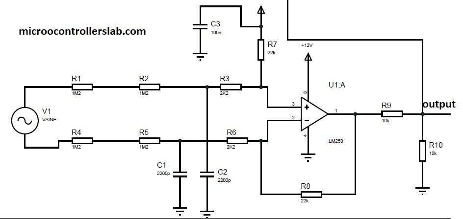
Input to difference amplifier is 220 volt ac and output of difference amplifier is less than 3.3 volt. I have also added 5 volt dc to ac to convert negative cycle into positive cycle. Because Arduino can not measure negative voltage directly. Again refer to the article on ac voltage measurement using pic microcontroller for more understanding and why I added 5 volt dc level to the circuit. Output of this circuit is fed to analog channel of Arduino which measures this voltage and after performing some calculations displays measured voltage value on LCD.
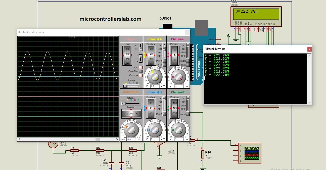
Video simulation in Proteus
Circuit diagram of AC voltage measurement using Arduino
Circuit diagram of ac voltage measurement using Arduino is given below. In this circuit, we used a 16×2 LCD to display voltage value. If you don’t know how to interface an LCD with Arduin, you should read this article:

Arduino Code
#include <LiquidCrystal.h>  // initialize the library with the numbers of the interface pins
LiquidCrystal lcd(12, 11, 5, 4, 3, 2);
const int sensorIn = A3;
double Voltage = 0;
double VRMS = 0;
int i;

void setup(){
 Serial.begin(9600);
 lcd.begin(16,2); // set up the LCD’s number of columns and rows:
}

void loop(){

  VRMS = voltage_READ();
  lcd.setCursor(0,0);
  lcd.print("V=");
  lcd.print(VRMS);
  lcd.print("V");
  Serial.print("V = ");
  Serial.print(VRMS);
  Serial.println("V");
  delay(1000);
}


 float voltage_READ(void)
 {
 float max;
 int i;
 unsigned int temp=0;
 float maxpoint = 0;
 for(i=0;i<500;i++)
      {
         if(temp =analogRead(sensorIn),temp>maxpoint)
         {
            maxpoint = temp;
         }
      }

maxpoint = maxpoint *(10.0/1023.0);
maxpoint = (maxpoint -5.0);
maxpoint = maxpoint *110.1909091;
 max=maxpoint *.707106781;
 return max;
 }
How Code works?
First include the library of liquid crystal display and define the pin number of Arduino that we connect with 16×2 LCD.
#include <LiquidCrystal.h>
LiquidCrystal lcd(12, 11, 5, 4, 3, 2);
We will use analog channel zero of Arduino (A0). This line defines the name of channel zero as a “sensorIn” pin. By doing this, we will use this symbolic name throughout the code instead of using ADC channel number.
const int sensorIn = A0;We define three global variables to store voltage value, adc digital value and to use with loops executions.
double Voltage = 0; // store ADC value
double VRMS = 0; //store RMS value of voltage
int i; // to keep count of loop value
Inside the setup function, we declare start the LCD library for 16×2 size using lcd.begin() function.
lcd.begin(16,2); // set up the LCD’s number of columns and rowsBefore taking a look inside the loop() function, first lets see the working of voltage_READ() routine.
Voltage Read Function
This is the main code of the Arduino AC voltmeter project. This function measures the peak voltage of the AC waveform and converts the peak voltage into a root mean square (RMS) voltage value.
Inside the AC voltage measurement function, first, we take 500 samples of AC voltage waveform using a for ‘loop’ and analog channel A0 of Arduino. Firstly, we initialize the “maxpoint” float type variable to zero and its value keeps updating with a new value of the ADC sample if the ADC sample value is greater than the currently hold value of “maxpoint”.
for(i=0;i<500;i++)
      {
         if(temp =analogRead(sensorIn),temp>maxpoint)
         {
            maxpoint = temp;
         }
      }
After that, this line converts the digital measured value of ADC into voltage.
maxpoint = maxpoint *(10.0/1023.0);Finally, we get original measured value of voltage by multiplying voltage value with the gain of operational amplifier.
maxpoint = (maxpoint -5.0);
 // subtract DC gain from the signal
maxpoint = maxpoint *110.1909091;
 // multiply with inverse of gain
max=maxpoint *.707106781; // peak to rms conversion
Is there any disadvantage of such circuit because it is not isolated.
can you please send me the code of this ac voltage measurement circuit using arduino. I tried this circuit by in lcd i couldn’t get the voltage as you mentioned in the video. please help me.Giving my email below. Thanks
let me know the issue you are facing by sharing your code in comments
I’m not sure about this method to become practical.
This is a non-isolated method.
it is better to use an optocoupler or transformer before to opamp to avoid electric shock and ground level difference
This method just works fine without any issue and I have implemented it many times. you will find this circuit in many modern inverters and power electronics circuits.
Although it is good to have optocoupler and transformer, But it will make system device costly.
my email id is anukmpl@gmail.com.thank you
You are right ????.
The reason behind that not just a 50 RS.
The circuit shown in above figure has better accuracy and precision.
Other circuits use a capacitor to filter ac components which is vulnerable to frequency.
Frequency is very according to load.
Please refer isolated opamps and ac voltage measuring ICs
Hello Sir
Yesterday i couldn’t reply you..i will tell what is the problem that i am facing when i am doing the project.. first of all i had referred your previous article ” Ac Voltage measurement using pic microcontroller “. I saw the code that you had given there for the ac voltage measurement using op-amp. i went through that code and i took the idea from there and i put it in my code.
i am using ATmega328P as my MCU for this project. i am not using Arduino for my project because in Arduino also they are using the same controller. But i am using avr studio as my IDE. i will give the code here.. I test this circuit in the proteus simulation. The problem that i am facing is when i run the code it doesn’t show the voltage that i can see in your simulation.i will share the pic also. Kindly check the code and tell me if there is any fault i made.
“””
#include
#include”LCD.h”
#include”DELAY.h”
void ADCInit();
int ReadADC(unsigned char);
unsigned int Get_AD_Data=0,count=0;
unsigned int Buff[30];
float Sum_AD=0;
volatile float Volt=0;
void main()
{
DDRD=0xff;
PORTD=0x00;
DDRC=0x00;
PORTC=0x00;
LCDInit();
Delay_ms(10);
LCDClear();
Delay_ms(5);
LCDDispStringXY(0,0,”Volt:-“);
Delay_ms(5);
ADCInit();
while(1)
{
for(count=0;count<30;count++)
{
Get_AD_Data = ReadADC(0);
Sum_AD = (Get_AD_Data * 10)/1024;
Sum_AD -= 5.0;
Buff[count] = Sum_AD*110.1909091;
Delay_us(30);
}
ADCSRA &=~(1<<ADEN);
Volt = Buff[0];
for(count=1;count<30;count++)
{
if(Volt<Buff[count])
{
Volt = Buff[count];
}
}
Volt *=0.707106781;
LCDDispIntXY(0,7,Volt,6);
ADCSRA |=(1<<ADEN);
Delay_ms(500);
}
}
void ADCInit()
{
ADMUX=0x00;
ADCSRA|=(1<<ADEN)|(1<<ADPS2)|(1<<ADPS1)|(1<<ADPS0)|(1<<ADATE);
}
int ReadADC(unsigned char ch)
{
ch &=0x0f;
ADMUX &= ch;
ADCSRA|=(1<<ADSC);
while(!(ADCSRA & (1<<ADIF)));
return(ADC);
} """
Hi
Unfortunately I do not have tutorial related to atmega,
I will try to write about it in future
Sir,Please send me the code ..
Hi Dear,
I am looking for a arduino module to check the the availability for Main AC Voltage i.e 220 V 50-60Hz. I have found one module for checking just the availability but i am stuck with the module which can give me the magnitude of the voltage means accurate reading either the voltage is very high or too low.
Can you please help me.
Regards.
Khurram
Hi
What is lowest and maximum range of AC voltage it can measure?
How to connect AC line and neutral here? I think we have to connect line voltage to + terminal side and neutral to – terminal side, is it? Please confirm
Thanks
Manjunath AN
Hi
What is lowest and maximum range of AC voltage it can measure?
How to connect AC line and neutral here? I think we have to connect line voltage to + terminal side and neutral to – terminal side, is it? Please confirm
Thanks
Manjunath AN
Hi,
1. Can I use LM358 instead of LM258? if Okay, Do I need to change any circuit?
2. Can I supply +5v instead of +12v to OPAMP?
3. What is the minimum and maximum AC voltage range it can measure?
4. How the ac line connection should be? My understanding is line voltage to + terminal neutral should give to – terminal? is it correct?
Please confirm
Thanks
Manju an
hi
can i have a code for voltage measurement with Arduino project please …
u can send to me by Email: abuod89@gmail.com
Thanks
Hy
Please sir can you help me with the code for automatic transfer switch between solar inverter and grid
I am doing my project base on that and i saw your simulation video but i could’nt find the code
Am using arduino uno
Pls help me with the code
Does this circuit actually work? I made it in LTspice and the output looks like a turd.
yes it works and we checked on hardware also.
Where is neutral connection…is it connect with ground of arduino
Sir when i simulated this circuit in proteus it worked excellent but when i implemented the hardware the output is a square type wave with noise not a sin wave what might go wrong in the circuit
Hi if i use this as simulation i got sine wave but when i implemented this as hardware i get a square wave only two values 1023 and 0 can you tell me where i might go wrong
i want made 16 chanel current and voltage monitor in blynk aspp
can you write a code
Hi Sir, I have used your code with ZMPT101B ARCELI module and all works good on laboratory, but when I connect the same circuit on the output of a gridline inverter connected on 230V AC line of my home and have the fridge working, than I have an error of about +8% of voltage measure. Please have you samething to suggest to avoid this? May be a filter for noise? Thank You Best Regards
is R7 not wrong and should be connected to gnd?