In this Arduino project, we will create a Wi-Fi based home automation system using ESP-01 Wi-Fi module and Arduino. We will use a free-to-use Android application called S remote to control home appliances. In this project, we will use ESP8266 WiFi module with Arduino to communicate with the Andriod app over Wi-Fi. We will send commands from Android application to control home appliances.
Arduino Uno R3 does not support Wi-Fi capabilities hence we have to use a separate Wi-Fi module to enable Wi-Fi connectivity. Therefore, we will interface and program ESP-01 Wi-Fi module with Arduino to enable Wi-Fi features. We will use Arduino IDE to program our Arduino with ESP-01 and LCD. AT commands through the serial port that is UART will be used to configure the ESP-01 Wi-Fi module.
We also have a similar project using pic microcontroller based home automation over wifi. You may also like to check it as well.

Recommended Components
The following components are used in this project or are helpful for building it with the Arduino.
| Component | How it’s used in this project | Buy on Amazon |
|---|---|---|
| Arduino Uno R3 | The main controller board that drives the home-automation logic. | Check Price |
| ESP8266 ESP-01 WiFi module | Provides WiFi connectivity so the system can be controlled over the cloud. | Check Price |
| Relay module | Switches the AC home appliances on and off under Arduino control. | Check Price |
| Breadboard | Solderless board to build and prototype the circuit without soldering. | Check Price |
| Jumper Wires | Used to make the connections between the Arduino, breadboard, and modules. | Check Price |
As an Amazon Associate we earn from qualifying purchases. Prices and availability are accurate as of the date/time indicated and are subject to change.
Wi-Fi based Home Automation System Overview
We will require the following components for this project.
Required Components:
- Arduino Uno: We will use Arduino due to its easy use. It also provides several digital pins to interface with the LCD, ESP8266 Wi-Fi module, and relay module at the same time. It is very friendly when you prototyping any project.
- 4 Channel Relay Modules: Relay is used to switch on and off higher voltage devices by using low dc voltages such as signal from the Arduino digital pin. In this project, we will use 4 channel relay module. It is easy to interface with Arduino instead of connecting each relay separately. It can bear up to 250VAC and 10 amps of current.
- 16×2 LCD: 16×2 LCD is used to display 16 characters in two lines. It is easy to interface with Arduino due to its available library. In this project, this LCD is used to display the status of the appliances.
- ESP8266 Wi-Fi Module: ESP8266 is a Wi-Fi chip that provides Transfer Control Protocol (TCP) and Internet Protocol (IP). There are different ESP8266 modules available in the market. In this project, we will use ESP-01. It has 6 pins and operates on 3.3v.
- AC bulbs with holders: AC bulbs are used to represent devices and appliances. Because it is easy to handle and very useful when you are prototyping any AC project. In the final product, you can just replace it with an AC socket to control.
- AC wire with plug: Use good quality wire when working with higher voltages. It is always good to use electrical tape to cover connections.
- External 5 volt supply: 5 volt dc supply is required to switch the relay ON and OFF. Otherwise, it does not work. Also do not supply 5v from Arduino.
How does WiFi-Based Home Automation Work?
In this WiFi-controlled home automation system, Arduino Uno is used as the brain of our circuit.
You can view the operations constituting the Wi-Fi control home automation system in the block diagram below

Connection Diagram of Wi-Fi controlled home automation system
This section will explain the connections of the various components specified above with Arduino Uno to form the home automation system.

Let us discuss them one by one.
Arduino with ESP-01
The ESP-01 module consists of 8 pins. The diagram below shows its pinout.
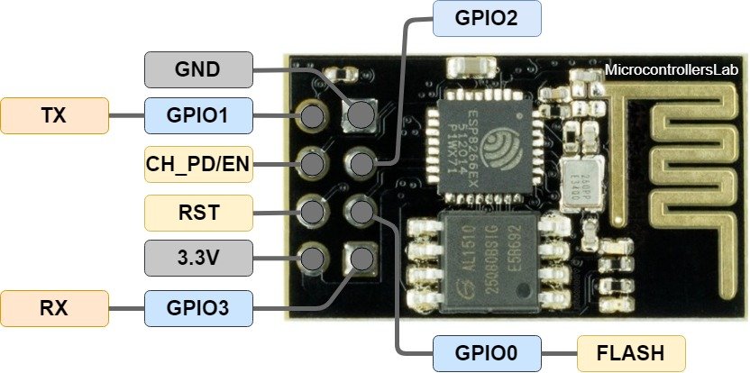
However, we will use 5 of these pins to connect with Arduino. These include the VCC, EN, GND, RX, and TX pins. RX and TX pins of the module will be connected with the UART pins of Arduino UNO. Arduino Uno has a single UART interface found on pin 0 (RX0) and pin 1 (TX0).
The table below shows the connections that we will use to connect the two devices:
| ESP-01 | Arduino UNO |
|---|---|
| VCC | 3.3V |
| EN | 3.3V |
| GND | GND |
| TX | RX0 |
| RX | TX0 |
Arduino with 16×2 LCD
We will use a 16×2 LCD in our project to display the states of the appliances. To connect a 16×2 LCD with Arduino we will require an additional 10k potentiometer as well.
We have a dedicated tutorial regarding interfacing 16×2 LCD display with Arduino with some example sketches. Have a look at it before proceeding further for a better understanding of the LCD.
Recommended Reading: 16×2 LCD Interfacing with Arduino – Explained with Example Codes
There are two types of pins on the whole 16×2 LCD module. Some pins are used to send to 16×2 LCD and some are command pins. In other words, every pin has a role in controlling a single pixel on the display.16 x 2 LCD has sixteen columns and two rows. That means, it can display sixteen characters per row and it has two such rows.
Pinout
The diagram shows the pin configuration of a 16×2 LCD display. It has sixteen pins.

- D0 – D7: Pin number 7-14 are data bus lines that are used to send data from Arduino which you want to display on LCD. With these 8 data lines, data can be transferred either in an 8-bit format or in a 4-bit format. In a 4-bit format, only upper four bits (D4-D7) are used to send data from Arduino to LCD. The full byte is transmitted in two successive transmissions. A 4-bit format is used to save GPIO pins of Arduino. Because fewer GPIO pins of Arduino will be required to transfer data.
- Contrast Select (VEE): It will help to control the contrast of PIXELS according to the 16X2 LCD light.
- RS: This pin is known as a register select pin. It helps to toggle the command/data register.
- R/W: The signal on this pin will decide whether it is going to read from LCD or write on it.
- EN: Enable pin will help to transfer the instruction from the data pins and another command pin to the LCD. It act as permission to internal registers.
- VSS: It’s a ground pin for common grounds.
- VCC: The power pin will use for voltage input to the 16X2 LCD.
Arduino connections with 16×2 LCD
We are using the following connections as described below. Refer to the schematic diagram to have a clearer idea of the connections.
| 16×2 LCD | Arduino |
|---|---|
| D4 – D7 | Pin A2,A3,A4,A5 |
| Enable | Pin A1 |
| RS | Pin A0 |
| RW | GND |
| VEE | 10k POT (Middle Leg) |
| VSS | GND |
| VCC | +5V |
| LED+ | +5V |
| LED- | GND |
We have an Arduino library for easy communication between LCDs called the LiquidCrystal library. It is an inbuilt library by Arduino Adafruit version.
Arduino with Channel Relay modules
The relay module for Arduino is one of the most powerful applications for Arduino as it can be used to control both A.C and D.C devices by simply controlling the relay by giving 5V. A relay is basically a switch that is operated electrically by an electromagnet. A relay can be used to control high voltage electronic devices such as motors as well as low voltage electronic devices such as a light bulb or a fan.
We will be using the 4 relay Arduino module in our home automation project.
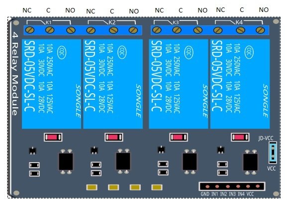
- External 5 volt to JD VCC.
- Ground to ground.
- IN1 to Pin 3.
- IN2 to Pin 4.
- IN3 to Pin5.
- VCC to Arduino 5v.
- Connect one terminal of all bulbs to normally open terminal of relays.
One end of 220VAC to all common terminals of relay and other ends with other terminals of bulbs.
Wi-Fi Controlled Home Automation System Arduino Code
We will use Arduino IDE to program our Arduino board.
Arduino Sketch
Open your Arduino IDE and go to File > New to open a new file. Copy the code given below in that file and save it.
#include<LiquidCrystal.h>
#include <SoftwareSerial.h>

LiquidCrystal lcd(A0, A1, A2, A3, A4, A5);

#define Fan 3
#define Light 4
#define TV 5

int temp = 0, i = 0;
int led = 13;
char str[15];

void setup()
{
  lcd.begin(16, 2);
  Serial.begin(9600);

  Serial.print("AT\r\n");
  delay(200);
  Serial.print("AT+CWMODE=3\r\n");
  delay(200);
  Serial.print('AT+CWJAP="YOUR_SSID","YOUR_PASSWORD"\r\n', timeout = 5000)
  delay(4000);
  Serial.print("AT+CIFSR\r\n");
  delay(200);
  Serial.print("AT+CIPMUX=1\r\n");
  delay(200);
  Serial.print("AT+CIPSERVER=1,80\r\n");
  delay(200);
  pinMode(led, OUTPUT);
  pinMode(Fan, OUTPUT);
  pinMode(Light, OUTPUT);
  pinMode(TV, OUTPUT);
  digitalWrite(Fan, HIGH);
  digitalWrite(Light, HIGH);
  digitalWrite(TV, HIGH);
  lcd.setCursor(0, 0);
  lcd.print("WI-FI Control ");
  lcd.setCursor(0, 1);
  lcd.print("Home AutomatIon");
  delay(2000);
  lcd.clear();
  lcd.clear();
  lcd.setCursor(0, 0);
  lcd.print("Fan Light TV ");
  lcd.setCursor(0, 1);
  lcd.print("OFF OFF OFF ");
}
void loop()
{
  lcd.setCursor(0, 0);
  lcd.print("Fan Light TV");
  if (temp == 1)
  {
    check();
    temp = 0;
    i = 0;
    delay(1000);
  }
}
void serialEvent()
{
  while (Serial.available())
  {
    if (Serial.find("#A."))
    {
      digitalWrite(led, HIGH);
      delay(1000);
      digitalWrite(led, LOW);
      while (Serial.available())
      {
        char inChar = Serial.read();
        str[i++] = inChar;
        if (inChar == '*')
        {
          temp = 1;
          return;
        }
      }
    }
  }
}
void check()
{
  if (!(strncmp(str, "tv on", 5)))
  {
    digitalWrite(TV, LOW);
    lcd.setCursor(13, 1);
    lcd.print("ON ");
    delay(200);
  }

  else if (!(strncmp(str, "tv off", 5)))
  {
    digitalWrite(TV, HIGH);
    lcd.setCursor(13, 1);
    lcd.print("OFF ");
    delay(200);
  }

  else if (!(strncmp(str, "fan on", 6)))
  {
    digitalWrite(Fan, LOW);
    lcd.setCursor(0, 1);
    lcd.print("ON ");
    delay(200);
  }

  else if (!(strncmp(str, "fan off", 7)))
  {
    digitalWrite(Fan, HIGH);
    lcd.setCursor(0, 1);
    lcd.print("OFF ");
    delay(200);
  }

  else if (!(strncmp(str, "light on", 8)))
  {
    digitalWrite(Light, LOW);
    lcd.setCursor(7, 1);
    lcd.print("ON ");
    delay(200);
  }

  else if (!(strncmp(str, "light off", 9)))
  {
    digitalWrite(Light, HIGH);
    lcd.setCursor(7, 1);
    lcd.print("OFF ");
    delay(200);
  }


}
How does the Code Work?
We will start by including all the necessary libraries required for this project as shown below:
#include<LiquidCrystal.h>
#include <SoftwareSerial.h>
Next, we declare the Arduino pins that are connected with the LCD. To define connections, we use the following line of code. This line creates a LiquidCrystal object and lcd is a name of the object that we are going to use to call LCD functions. You can also use any other name.
LiquidCrystal lcd(rs, en, d4, d5, d6, d7)In our case, the pins are 8, 9, 10, 11, 12, and 13 respectively.
LiquidCrystal lcd(A0,A1,A2,A3,A4,A5);Specify the Arduino pins connected with IN1, IN2 and IN3 of 4 Channel Relay Module. These pins will control fan, light and tv. For demonstration purposes we are using bulbs.
#define Fan 3
#define Light 4
#define TV 5
Moreover, we will define some other variables as well including a temporary variable called ‘temp’ with the value 0, an array of 15 characters called str that we will use later on in the code to monitor the appliances appropriately.
int temp = 0, i = 0;

char str[15];
Additionally, we will blink a 5mm LED connected with the Arduino digital pin 13, whenever data is being received from the android application. In the following line, we are defining the pin number of the led variable.
int led = 13;setup()
Next, we use lcd.begin() routine to define the size of an LCD. The first argument to this function is a number of rows and the second argument is a number of columns. For instance, this line declares the size as 16 columns and 2 rows. That means 16×2 size.
lcd.begin(16, 2);Open the serial communication at a baud rate of 9600.
Serial.begin(9600);Use a series of AT commands to initialize ESP8266 Wi-Fi module.
AT: This type of command is used to test the startup function of Wi-Fi module. The response would be ok, against this command if everything is ok.
Serial.print("AT\r\n");AT+CWMODE=3 : This sets the Wi-Fi mode of ESP8266 in this case in Station + SoftAP.
Serial.print("AT+CWMODE=3\r\n");AT+CWJAP=”SSID”,”PASSWORD”\r\n’, timeout=TIME_ms : This connects the ESP8266 with an AP whose SSID and password are given, The timeout here is the reconnection time.
Serial.print('AT+CWJAP="YOUR_SSID","YOUR_PASSWORD"\r\n', timeout=5000) #Connect to APAT+CIFSR: This command obtains the local IP address.
Serial.print("AT+CIFSR\r\n");AT+CIPMUX=1:This command is used to enable multiple connections (maximum 4)
Serial.print("AT+CIPMUX=1\r\n");AT+CIPSERVER=1: This command configures ESP8266 as server.
Serial.print("AT+CIPSERVER=1,80\r\n");Configure led, fan, light and TV as output pins by using pinMode() function. Specify the pin as the first parameter and the mode as the second parameter.
  pinMode(led, OUTPUT);
  pinMode(Fan, OUTPUT);
  pinMode(Light, OUTPUT);
  pinMode(TV, OUTPUT);
Initially set the value to HIGH by using digitalWrite() function. Specify the pin as the first parameter and the value as the second parameter.
  digitalWrite(Fan, HIGH);
  digitalWrite(Light, HIGH);
  digitalWrite(TV, HIGH);
Print a series of messages on the LCD display with delays in between. Initially all the three bulbs are off hence it will be displayed on the LCD that Fan Light TV are all OFF.
  lcd.setCursor(0, 0);
  lcd.print("WI-FI Control ");
  lcd.setCursor(0, 1);
  lcd.print("Home AutomatIon");
  delay(2000);
  lcd.clear();
  lcd.clear();
  lcd.setCursor(0, 0);
  lcd.print("Fan Light TV ");
  lcd.setCursor(0, 1);
  lcd.print("OFF OFF OFF ");
loop()
Inside the infinite loop() we first check if the temporary variable we created is ‘1’ or not. If it is then call the check() function that will be responsible for controlling the appliances by comparing the received data and the command in the application. Moreover, the temporary variable is again set to 0.
void loop()
{
  lcd.setCursor(0, 0);
  lcd.print("Fan Light TV");
  if (temp == 1)
  {
    check();
    temp = 0;
    i = 0;
    delay(1000);
  }
}
serialEvent()
This function is automatically called at the end of loop() when there is serial data available in the buffer. In our case, if the data available in the buffer consists of ‘#A’ then the LED will blink and the characters are added to the array str. If the available character is ‘*’ then the temporary variable will be set 1 and we return.
void serialEvent()
{
  while (Serial.available())
  {
    if (Serial.find("#A."))
    {
      digitalWrite(led, HIGH);
      delay(1000);
      digitalWrite(led, LOW);
      while (Serial.available())
      {
        char inChar = Serial.read();
        str[i++] = inChar;
        if (inChar == '*')
        {
          temp = 1;
          return;
        }
      }
    }
  }
}
check()
The check() function is responsible for controlling the appliances by comparing the strings received in the buffer and the command button in the application. In the first case, if ‘tv on’ button was pressed, then turn the TV on. Otherwise, if ‘tv off’ button was pressed, then turn the TV off. Likewise, if ‘fan on’ button was pressed then turn the Fan ON. Otherwise, if ‘fan off’ button was pressed, then turn the Fan OFF. Likewise, if ‘light on’ button was pressed then turn the Light ON. Otherwise, if the ‘light off’ button was pressed then turn the Light OFF.
The LCD will display all the states of the three appliances as they change at each step.
void check()
{
  if (!(strncmp(str, "tv on", 5)))
  {
    digitalWrite(TV, LOW);
    lcd.setCursor(13, 1);
    lcd.print("ON ");
    delay(200);
  }

  else if (!(strncmp(str, "tv off", 5)))
  {
    digitalWrite(TV, HIGH);
    lcd.setCursor(13, 1);
    lcd.print("OFF ");
    delay(200);
  }

  else if (!(strncmp(str, "fan on", 6)))
  {
    digitalWrite(Fan, LOW);
    lcd.setCursor(0, 1);
    lcd.print("ON ");
    delay(200);
  }

  else if (!(strncmp(str, "fan off", 7)))
  {
    digitalWrite(Fan, HIGH);
    lcd.setCursor(0, 1);
    lcd.print("OFF ");
    delay(200);
  }

  else if (!(strncmp(str, "light on", 8)))
  {
    digitalWrite(Light, LOW);
    lcd.setCursor(7, 1);
    lcd.print("ON ");
    delay(200);
  }

  else if (!(strncmp(str, "light off", 9)))
  {
    digitalWrite(Light, HIGH);
    lcd.setCursor(7, 1);
    lcd.print("OFF ");
    delay(200);
  }


}
Demonstration
Make sure you choose the correct board and COM port before uploading your code to the board. Go to Tools > Board and select Arduino UNO. Next, go to Tools > Port and select the appropriate port through which your board is connected.

Click on the upload button to upload the code to the board.
After you have uploaded your code to the development board, open the serial monitor and set the baud rate to 9600. In a few moments, the Wi-Fi will get connected and you will receive an IP address.
Next, download the S Remote control application from Google Play Store.
Open the application, go to Setting>>Advance>>Layout, and select the Button according to your desire.
Then select IP and enter the IP address which we got when we initialized ESP8266 Wi-Fi module using this command “AT+CIFSR”. The IP address is written in the third line such as “192.168.10.4”. Then write the port which is “80” in the port option.
Go to Setting>>Keys and then select key1 and write the label to display on button and then the data which you want to send to Arduino. Click the TCP button.
Similarly, write the label and data in other keys.

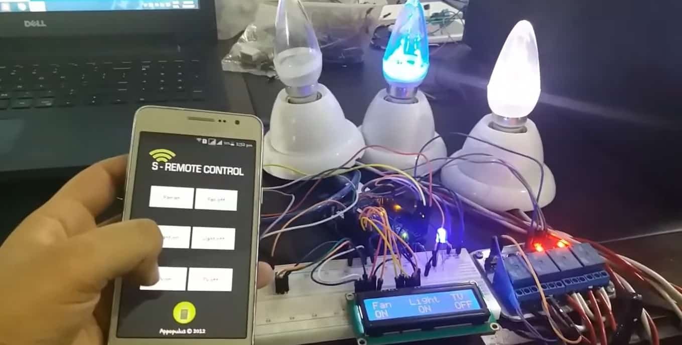
Press the button on the application. This data is sent by the application to Arduino through Wi-Fi and then the Arduino performs operations accordingly.
Watch the video below to have a better insight:
You may like to read:
how much this project worth? i just need it to my project pls response to my mssg thank you
it is very important for me.t hank you!!!
please clear the connection
what about to add stove and refrigerator
I tried to download sremote but it is not available on google play, would you share me that app via email?