In this tutorial, you will learn how to interface LCD with Arduino. We will be using Arduino Uno, but the same code and concepts work for other Arduino development boards also. Firstly, 16×2 LCD interfacing with Arduino will be discussed. After that, we will also provide examples of 16×4 LCD and I2C LCD interfacing with Arduino.

Recommended Components
The following components are used in this project or are helpful for building it with the Arduino.
| Component | How it’s used in this project | Buy on Amazon |
|---|---|---|
| Arduino Uno R3 | Drives the LCD over its parallel data pins and runs the display sketch. | Check Price |
| 16×2 LCD (parallel) | The character display that shows text output – the main module of this project. | Check Price |
| 10kΩ potentiometer (contrast) | Adjusts the LCD contrast voltage on the VO pin so the characters are readable. | Check Price |
| Breadboard | Holds the LCD and potentiometer for solderless prototyping. | Check Price |
| Jumper Wires | Connect the LCD data/control pins and contrast pot to the Arduino. | Check Price |
As an Amazon Associate we earn from qualifying purchases. Prices and availability are accurate as of the date/time indicated and are subject to change.
Why We need to Interface LCD with Arduino?
The first question that must come to your mind is that why we need to interface LCD with Arduino? There are many applications in embedded projects in which wants to display different types of data on LCD. For example, it is used to display different sensors data such as temperature, humidity, pressure, light intensity, voltage, current and many others. Hence, the use of liquid crystal displays is very popular and common in Arduino project. It is also recommended to learn LCD interfacing at the start. Because when you learn to interface sensors with Arduino, you will already have a coding experience to display that sensor value.
Liquid Crystal Display Introduction
As its name suggests LCDs are electronics devices that are used to display texts, custom characters, and numbers. Although, we can also display pictures on LCDs. But results will be not comparable to graphical LCDs (GLCDs). GLCDs are used to display images. Coming back to LCDs, they are available in different sizes and features. For example, 16×2, 20×2, 16×1 are different sizes available.
Types
They come in two types serial and parallel LCDs. Serial type uses serial communication, such as the UART module, to interface with Arduino. They are easier to interface with Arduino than parallel LCDs. But they are expensive. In contrast, parallel LCDs, for example, Hitachi HD44780, are exceptionally used and interfacing with Arduino is done using digital I/O pins of Arduino. For instance, Hitachi HD44780 type 16×2 LCD can be interfaced with Arduino using 4-8 data lines and few control pins of the display. In this tutorial, we will be using 16×2 parallel LCD only. Because it is the most popular choice among the Arduino community and embedded application developers.
16×2 LCD Introduction
There are two types pins on the whole 16×2 LCD module. Some pins are used to send to 16×2 LCD and some are command pins. In other words, every pin has a role in controlling a single pixel on the display.
16 x 2 LCD has sixteen columns and two rows. That means, it can display sixteen characters per row and it has two such rows. Similarly, 20×4 LCD has four rows and 20 columns. That means, it can display 20 characters per row.
Pinout Diagram
The diagram shows the pin configuration of 16×2 display. It has sixteen pins.

D0 – D7: Pin number 7-14 are data bus lines that are used to send data from Arduino which you want to display on LCD. With these 8 data lines, data can be transferred either in an 8-bit format or in a 4-bit format. In a 4-bit format, only upper four bits (D4-D7) are used to send data from Arduino to LCD. The full byte is transmitted in two successive transmissions. A 4-bit format is used to save GPIO pins of Arduino. Because fewer GPIO pins of Arduino will be required to transfer data.
Contrast Select (VEE): Pin3 will connect with power and ground through 3 pin potentiometers. It will help to control the contrast of PIXELS according to the 16X2 LCD light. 10K ohm variable resistor is connected with the VEE pin to adjust light contrast. Variable resistor one side is connected with 5 volts and the other side is connected with ground. The third terminal is connected with the VEE pin.
RS: This pin is known as a register select pin. It helps to toggle the command/data register.
R/W: The signal on Pin5 will decide whether it is going to read from LCD or write on it.
EN: Enable pin will help to transfer the instruction from the data pins and another command pin to the LCD. It act as permission to internal registers.
VSS: It’s a ground pin for common grounds.
VDD: The power pin will use for voltage input to the 16X2 LCD.
In Arduino, we don’t need to worry about controlling these data lines and control registers. Because Arduino provides rich library resources. LCD library comes with Arduino IDE by default when we install it.
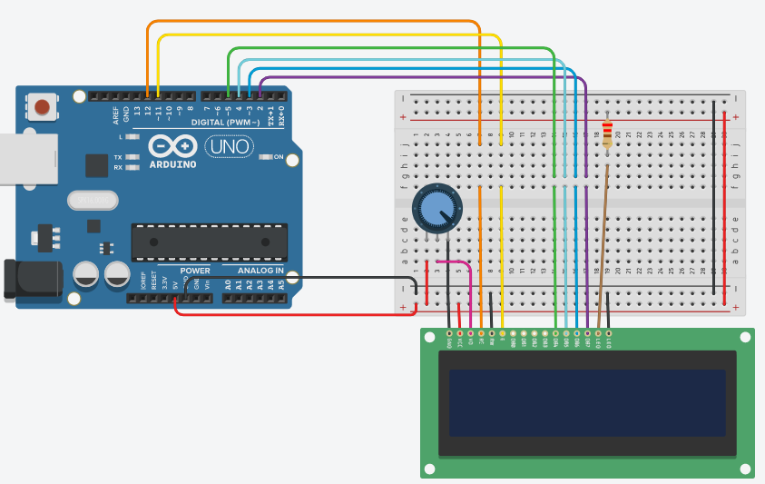
16×2 LCD Interfacing Schematic Diagram
This picture shows the connection diagram of Arduino with 16×2 LCD.
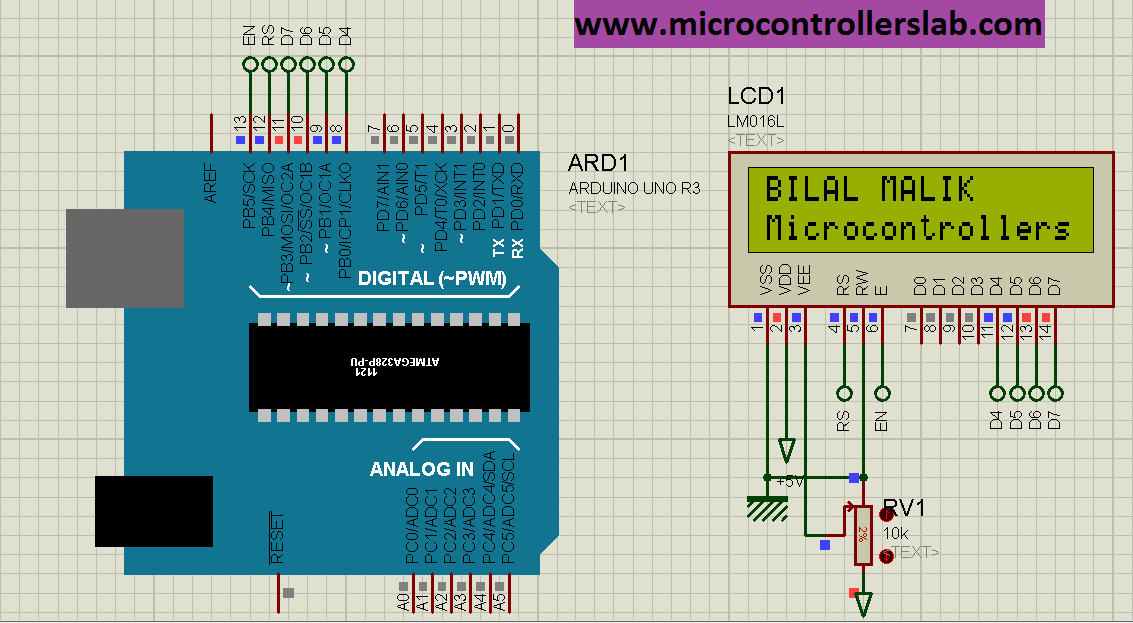
If you are having to read connections according to above schematic, you can check this table for connections between Arduino and 16×2 LCD.
| 16X2 LCD | Arduino |
|---|---|
| D4 – D7 | 9, 10, 11, 12 |
| E | 7 |
| RS | 4 |
| VEE | POT (Middle Leg) |
| VSS | Ground |
| VDD | +5V |
| D+ | +5V |
| D- | Ground |
More information on 16×2 LCD working and pin configuration available on this link:
Arduino 16×2 LCD Library Functions
In this section, we will discuss different LCD control routines that are available in Arduino IDE. Most importantly, the same library function is used for all types of parallel LCDs such as 16×1, 16×2, 20×1, 20×4, etc.
Firstly, we should include a header file. This header file contains prototypes and function definitions that are used to control display.
#include <LiquidCrystal.h>LCD Connections Declaration
The second most important thing is the declaration of Arduino pins that are connected with LCD. To define connections, we use this line. This line created a “LiquidCrystal” object and “lcd” is a name of the object that we are going to use to call LCD functions. You can also use any other name.
LiquidCrystal lcd(rs, en, d4, d5, d6, d7).Lets say, we want to use any other name instead of LCD, we can define it like this:
LiquidCrystal myname(rs, en, d4, d5, d6, d7);But now to call every you will use this name like myname.print(), myname.begin() etc.
Here the first argument defines the connection of the RS pin of the LCD with the Arduino pin, the second argument is the EN pin, and so on. Let’s take an example. In this example, first, we give a name to each digital pin of Arduino. It will make the code easier to read and understand.
const int rs = 12, en = 11, d4 = 5, d5 = 4, d6 = 3, d7 = 2;According to this declaration, you must connect RS pin of LCD to digital pin 12, En to 11 and so on.
LiquidCrystal lcd(rs, en, d4, d5, d6, d7);LCD Size
Till now, we have defined the LCD connection and included its library. After that, we must define the size of the LCD. This lcd.begin() routine is used to define the size of an LCD. The first argument to this function is a number of rows and the second argument is a number of columns. For instance, this line declares the size as 16 columns and 2 rows. That means 16×2 size.
lcd.begin(16, 2);Similarly, we can specify the size according to the display we want to use.
Now lets see a simple 16×2 LCD program to print text. This program prints “ABC” as shown in figure below.
#include <LiquidCrystal.h>
const int rs = 12, en = 11, d4 = 5, d5 = 4, d6 = 3, d7 = 2;
LiquidCrystal lcd(rs, en, d4, d5, d6, d7);
void setup()
{
  lcd.begin(16, 2);
  lcd.print("ABC");
}

void loop()
{
  // put your main code here, to run repeatedly:

}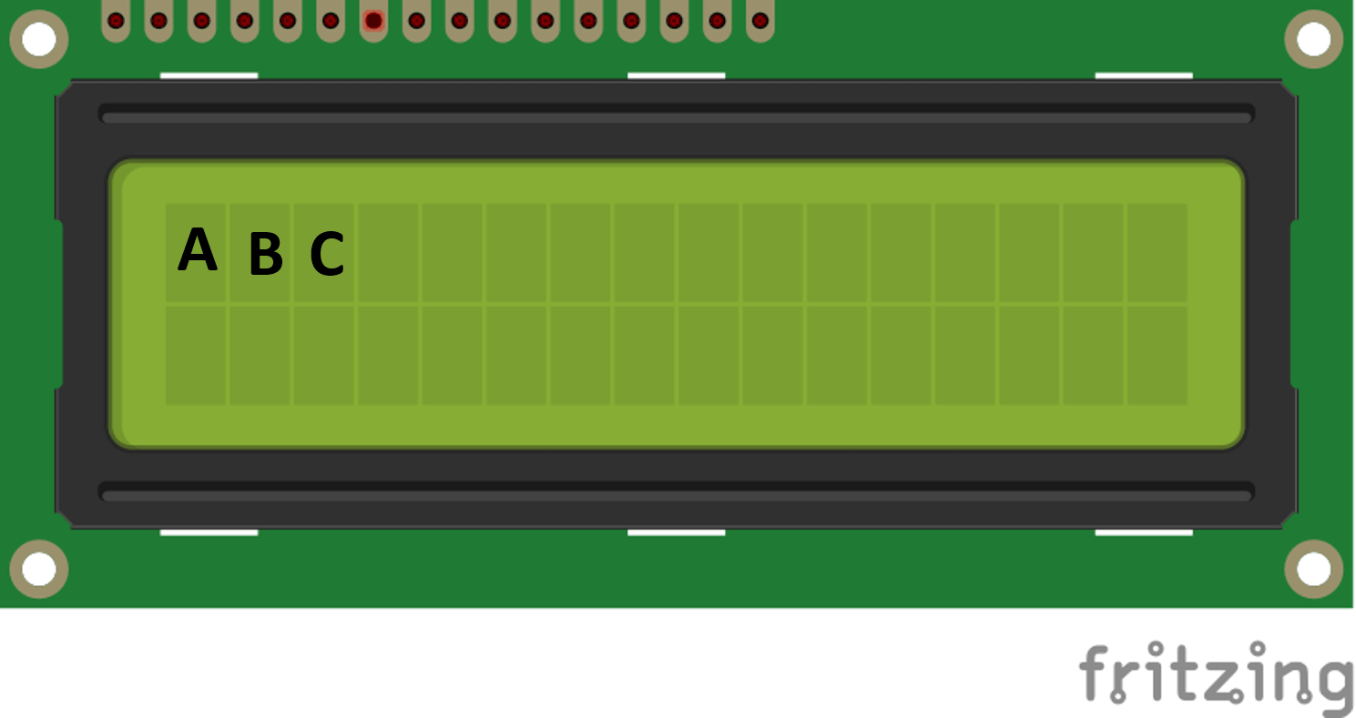
As expected above code displays “ABC”. The lcd.print() function is used to send data. The most important thing to consider in this code is the position of the displayed text. As you can see from the figure, it starts printing text from the first location of LCD that is the first row and first column such as (0,0). Basically , lcd.print() start to display text from the current cursor position of LCD. Now let’s understand how to control and set cursor location.
LCD Cursor Setting
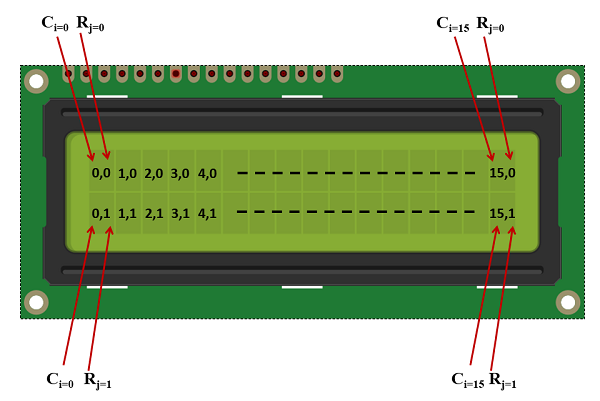
As you know that 16×2 LCD has 16 columns and two rows. One position can display only one ASCII character. Also, one location consists of one row and one column. For example, (0,0) means the first row and first column, (0,1) means the first row and second column, and similarly, (1,0) means the second row and first column. This picture shows the position of each location according to rows and columns of 16×2 LCD.
Now the question that must come to your mind is that how to display ASCII characters on a specific location using lcd.print()? Fortunately, that’s very easy with Arduino. It can be done by controlling the cursor position using lcd.setCursor() function.
lcd.setCursor() function is used to set the location where we want to display character or text. The first argument to this function is a column number and the second argument is the row number. For example, this line sets the cursor position of the Arduino to the second row and first column. Because counting of rows and columns starts from zero.
lcd.setCursor(0, 0); //set cursor to first column and first row
lcd.setCursor(15,0); //set cursor to 16th column and 2nd row
lcd.setCursor(0, 1); //set cursor to first column and 2nd row
lcd.setCursor(15, 1); //set cursor to 16th column and 2nd row
Now let’s see examples in order to understand LCD cursor position control with Arduino more clearly.
void loop()
{
lcd.setCursor(6, 1);
lcd.print(“ABC”);
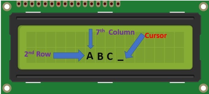
}This code provides the output as show in this figure. It displays “ABC” starting from 2nd row and 7th column position.
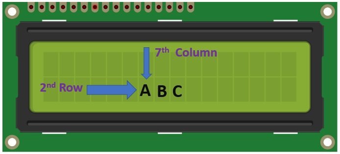
Another most important feature to note in this code is that LCD cursor position automatically moves to the next position after displaying character on current position. In the above code, we set the cursor position to (1,6), but it also displays next characters such as ‘B’ and ‘C’ on the next location.
Visualize Cursor Position
Arduino library also provide function to visualize curson position. This code visualize advanced cursor position with underscore symbol.
void loop()
{
  lcd.setCursor(6, 1);
  lcd.print(“ABC”);
  lcd.cursor(); // this turns on cursor position by displaying underscore
}
The output of the above would be like this:
This auto cursor increment is very useful. Because we don’t have to set the cursor position again and again with the Arduino. Arduino will automatically display text to next the position.
Arduino 16×2 LCD Interfacing Example
As shown in the above circuit diagram, this circuit will display “BILAL MALIK” in the first row of LCD and “microcontrollers” in the second row of LCD. It is also shown in the above diagram, pin number 9-12 of Arduino UNO R3 is connected with LCD. you just have to write these pin numbers in LCD library functions arguments which tell Arduino that which pin of Arduino is connected with which pin of LCD. The code to display the above text which is showing on LCD is given below.
Arduino Sketch
// It inculde Liquid crystal display library in your code
 #include <LiquidCrystal.h>
 // This function assigns Arduino microcontroller about connection of LCD with Arduino. Pins should be connected in following manner :
 // LiquidCrystal(RS, EN, D4, D5, D6, D7)
 LiquidCrystal lcd(4, 7, 9, 10, 11, 12);

void setup()
{
 // following function set up the LCD columns and rows:
 lcd.begin(16, 2);
 }

void loop() {
 lcd.setCursor(0,0); // set the cursor position
 lcd.print("BILAL MALIK"); //print the string on cursor position
 lcd.setCursor(0,1);
 lcd.print("Microcontrollers");
 lcd.noDisplay(); // No display on LCD for 500ms
 delay(500);
 lcd.display();
 delay(500);
 }
Video Demo
Code is self-explanatory and we have also written comments along with each line of code. But if you still have any issue, let us know with your comments on this post.
Scrolling Text on 16×2 LCD using Arduino
In the last section, we have learned to display simple text on LCD using Arduino. Now let’s move to some advanced examples. In this section, we will discuss examples of scrolling text on LCD. That means moving text towards left and right direction.
Arduino LCD Text Scrolling Functions
Arduino LCD library supports two functions that are used to scroll text on LCD. These are routines are:
- lcd.scrollDisplayLeft();
- lcd.scrollDisplayRight();
As their name suggests, lcd.scrollDisplayRight(); moves the text one cursor position towards right from current text position and lcd.scrollDisplayLeft(); moves the text one cursor position towards left.
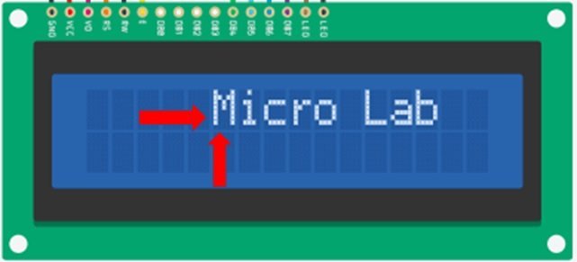
For example, in this picture LCD shows text “Micro Lab” on the 6th column and 1st row location.
Now if we call, lcd.scrollDisplayLeft(); function inside the code, it will move the text one position left and output will look like this:
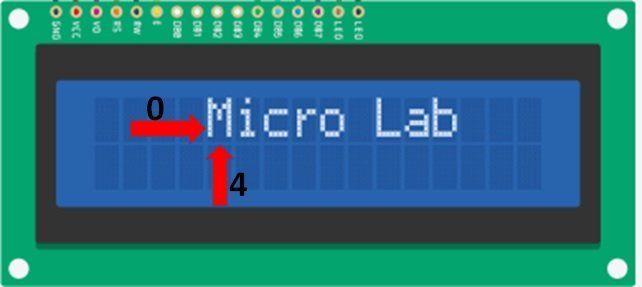
Similarly, if we call lcd.scrollDisplayRight(), it will move the text one position right and output will look like this:
Schematic Diagram
Make connection with Arduino and 16×2 LCD according to this schematic diagram:
Scolling Text Arduino Code
Upload this code to Arduino IDE.
#include<LiquidCrystal.h>
LiquidCrystal lcd(12,11,5,4,3,2);
void setup() {
  lcd.begin(16,2);
  lcd.setCursor(5, 0);
  lcd.print("Micro Lab");
}

void loop()
{
  for(int i=0; i<5; i++)
  {
    lcd.scrollDisplayLeft();
    delay(600);
  }
  for(int i=0; i<5; i++)
 {
    lcd.scrollDisplayRight();
    delay(600);
  }

}
The output of code would be like this:

How Code Works?
This code is quite similar to the last example except for the LCD scrolling part inside the loop() function.
First, we set the cursor position to location (5,0) using cursor setting routine.
lcd.setCursor(5, 0);After that, it prints the text “Micro Lab” on the current cursor position.
lcd.print("Micro Lab");As you know that if we call scrolling text left or right function of Arduino, they will move the text one one position towards left or right. Therefore, we used a loop to call these functions more than one time.
First, we call lcd.scrollDisplayLeft() 5 times using for loop iteration 5 times. Therefore, it moves the text towards left for 5 positions.
 for(int i=0; i<5; i++)
{
    lcd.scrollDisplayLeft();
    delay(600);
  }
After that, we call lcd.scrollDisplayRight() 5 times using for loop iteration 5 times. Therefore, it moves the text towards the right for 5 positions.
for(int i=0; i<5; i++)
{
    lcd.scrollDisplayRight();
    delay(600);
  }
Displaying Custom Characters on 16×2 LCD LCD using Arduino
In this section, we will learn to generate custom characters and learn to display custom characters on LCD using Arduino. Creating custom characters are useful when we want to display any symbol on LCD which is not available in the standard ASCII character set.
LCD Memory to store Custom Characters
As you know, the 16×2 LCD is based on the HD44780 controller. This controller has a butil-in character generation random access memory. CGRAM is used to display store user defined symbols or characters. Only 64 bytes of CGRAM is available. That means, due to limited memory, we can store a limited number of custom characters inside this memory.
For example, a 16×2 LCD with 5×8 pixels for each position, only 8 custom characters can be stored and similarly for 5×10 pixel, type, only four can be stored. But still, this is enough memory. Because usually we need 1-2 user defined characters only such as battery. Sound, lock, bell symbol, etc.
Custom Characters Generation
Each location in the 16×2 LCD consists of 5×8 pixels. Therefore, to generate custom patterns, we must turn on and turn off individual dots according to the character that we want to display.
To create custom symbols patterns, we can use an application available on this link.
Go to the above link and make any user-defined character by setting or clearing specific pixels from the 5×8 grid of pixels. Let’s say, we want to make a bell icon. Select pixels according to this picture and you will see the pattern code will be generated.
Similarly, you can generate as many user defined characters you want. But due to limited CGRAM, only 8 can be stored in the memory.
To display custom characters, first we must generate code for each character and after that store this value inside the CGROM of 16×2 LCD.We can store our custom generated characters inside CGRAM and load them to display on LCD.
Storing Character Inside CGRAM with Arduino
In order to store these patterns inside CGRAM, Arduino IDE provides a createChar() function. The input argument to this function is a pattern ( array of bytes) and an address. The address will be from 0-7. For example, we generated a pattern for a bell icon that is
byte bel[] = {
  B00100,
  B01110,
  B01110,
  B01110,
  B01110,
  B11111,
  B00000,
  B00100
};
To store this, we call lcd.Create() function like this
lcd.createChar(0, bell);It will store the user-defined character bell on location ‘0’ in CGRAM. Now if you want to write this letter on LCD, you can use lcd.Write() like this:
lcd.Write(byte(0));The important thing to note here is that we read character from the same location where lcd.Create() writes it.
Custom Characters Generation Arduino Code
Upload this code to Arduino. It displays user-defined symbols such as lock, sound, heart and bell on 16×2 LCD.
#include<LiquidCrystal.h>
LiquidCrystal lcd(12,11,5,4,3,2);
byte lock[8] = {
0b01110,
0b10001,
0b10001,
0b11111,
0b11011,
0b11011,
0b11111,
0b00000,};
byte sound[8] = {
0b00001,
0b00011,
0b00101,
0b01001,
0b01001,
0b01011,
0b11011,
0b11000} ;
byte speaker[8] = {0b00001,
0b00011,
0b01111,
0b01111,
0b01111,
0b00011,
0b00001,
0b00000,};
byte heart[8] = {0b00000,
0b01010,
0b11111,
0b11111,
0b01110,
0b00100,
0b00000,
0b00000 };
void setup() {
  lcd.clear();
  lcd.begin(16,2);
  lcd.createChar(0,lock);
  lcd.setCursor(0,0);
  lcd.write(byte(0));
  delay(600);
  lcd.createChar(1,sound);
  lcd.setCursor(4,0);
  lcd.write(byte(1));
  delay(600);
  lcd.createChar(2,speaker);
  lcd.setCursor(8,0);
  lcd.write(byte(2));
  delay(600);
  lcd.createChar(3,heart);
  lcd.setCursor(12,0);
  lcd.write(byte(3));
  // put your setup code here, to run once:

}

void loop() {
  // put your main code here, to run repeatedly:

}
The output of this code will look like this:

Write Serial Data on 16×2 LCD using Arduino
In this section, we will see how to write data on 16×2 LCD which receives on a serial pin of Arduino. For example, we will send a text from the serial monitor to Arduino and as soon as the Arduino serial pin receives this data, it will be displayed on LCD.
Arduino Code
This LCD interfacing example with Arduino demonstrates how to write serial data from Arduino serial monitor directly on 16×2 LCD.
#include<LiquidCrystal.h>
LiquidCrystal lcd(12,11,5,4,3,2);
byte ch;
int col=0;
int row=0;
void setup() {
  Serial.begin(9600);
  lcd.begin(16,2);
  lcd.clear();
  // put your setup code here, to run once:

}

void loop() {
  if(Serial.available()){
    char ch=Serial.read();
    Serial.write(ch);
    Serial.println();
    lcd.setCursor(col,row);
    lcd.write(ch);
    col++;

  if(col>15){
    row++;
    col=0;
    lcd.write(ch);
  }
  // put your main code here, to run repeatedly:

}
if(ch=='*' ||row==1&&col>=15){
  lcd.clear();
  col=0;
  row=0;
}
}
The above code works similar to the previous examples except for the serial communication section. Here, the UART communication of Arduino is used to receive characters from a user via a serial terminal. You can use a serial terminal of Arduino to send the character to the LCD that you want to display on the LCD. If you want to read more about the UART communication library of Arduino, you can read this tutorial:
Video Demo
Applications
Liquid crystal display has many applications in embedded systems and digital electronics projects. Engineering students used LCDs in their projects to display various types of parameters. I have posted many articles on embedded system projects.
In all these projects I have used liquid crystal display to display various physical parameters like temperature, analog current, analog voltage, humidity, the intensity of light, moisture, and solar panel parameters. In all these projects, I have used LCD to display these parameters.
In summary, this tutotrial, we learned:
- Display text on LCD
- LCD Cursor Setting with Arduini
- Scrolling Text on 16×2 LCD using Arduino
- Displaying Custom Characters on 16×2 LCD LCD using Arduino
- A way Custom Characters to store LCD Memory
- Custom Characters Generation for 16×2 LCD and Arduino
- Write Serial Data on 16×2 LCD using Arduino
You can read our other 16×2 LCD related tutorials here:
- 16×2 LCD Interfacing with PIC Microcontroller – Examples
- LCD Interfacing with TM4C123 Tiva LaunchPad – Keil uvision
- I2C LCD interfacing with ESP32 and ESP8266 in Arduino IDE
- LCD interfacing with MSP430 LaunchPad
- INTERFACING LCD WITH 8051 MIROCONTROLLER with code
You may also read the following topics to get an idea about the applications of LCD.
- Interface GT511C3 Fingerprint Scanner Module with Arduino
- AC voltage measurement using PIC microcontroller
- AC current measurement using PIC microcontroller
- Digital Temperature sensor
- Digital humidity sensor
- Intelligent greenhouse control system
- Solar panel parameters measurement system
- Interface LM35 Temperature Sensor with Arduino
Respected sir,
Hope u will be fine.. sir i need the complete diagrame and code of the GSM based electronic notice board using arduino with display.plz its my humble request that to send me this project thanks
Excellent, clear explanation. Thank you.
One typo is in the ABC explanation, second line, where I believe that should be “1st row.”
lcd.setCursor(0, 0); //set cursor to first column and first row
lcd.setCursor(15,0); //set cursor to 16th column and 2nd row <== 1st row?
lcd.setCursor(0, 1); //set cursor to first column and 2nd row
lcd.setCursor(15, 1); //set cursor to 16th column and 2nd row
Thank you again. I learned a lot, and have subscribed.
Hi Tim,
Thanks for pointing out a typo, we will fix it.