INA219 is a shunt Current Sensor module introduced by the Texas instruments. It is a Zero-Drift, Bidirectional, Power Monitor module that monitors shunt voltage, Bus voltage, current, and power. It has an integrated 12C or SMBus-compatible interface to communicate data to the microcontrollers.
The chip has an analog-to-digital converter with a high resolution of 12-bit and 16 programmable addresses for flexible configuration. It comes with an additional multiplier register that converts the power to watts. It is a small, low-power current sensing module that comes in handy for small embedded projects.

INA219 Current Sensor Module Components
The components of the 1NA219 Current Sensor Module are shown as under:

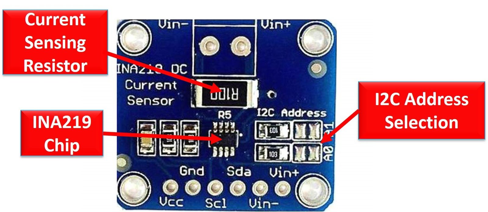
The module consists of an INA219 chip, I2C Bus, and a Current Sensing Resistor.
Current Sensing Resistor
The module has a shunt resistor to measure current, voltage, and power by measuring the voltage drop across it. It can be altered per requirement.
INA219 Chip
The integrated Circuit is responsible for all the signal and data processing.
I2C Interface: The I2C bus consists of SDA and SCL and serves the purpose of communicating data between the module and the microcontroller.
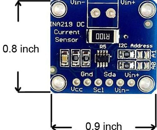
INA219 Pinout
The following diagram shows the pinout of the INA219 Current Sensor Module:
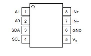
Let us discuss the pinout of the INA219 Current Sensor Module. The pin configuration detail in tabular is mentioned below:
| Pin Number | Pin Name | Function |
|---|---|---|
| 1 | A1 | Address1 pin |
| 2 | A0 | Address0 pin |
| 3 | SDA | Serial Data pin |
| 4 | SCL | Serial Clock pin |
| 5 | VS | Power Supply pin |
| 6 | GND | Ground pin |
| 7 | IN– | Positive Analog Input pin |
| 8 | IN+ | Negative Analog Input pin |
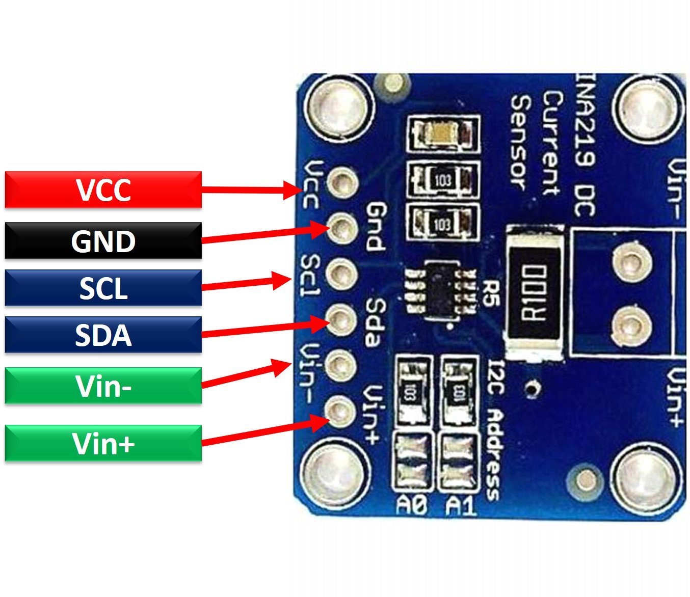
The following picture shows the pinout diagram of current sensor module and the pins which are exponses through header:
Features and Specifications
- Operational Voltage: 3 – 5.5 Volts
- Operating Temperature: -400C – 1250C
- Maximum Voltage: 6 Volts
- Bus Voltage Range: 0 – 26 Volts
- Current sensing Range: ±3.2A with ±0.8mA resolution
- 0.1 ohm 1% 2W current sense resistor
Useful Features
Some of the extra features include:
- It has in-built calibration registers to reduce uncertainty in the power, voltage, and current values.
- It contains 16 programmable addresses and filtering options.
- The sensor is available in 2 grades i.e. INA219A and INA219B.
- The Accuracy is up to 0.5% in INA219B over the temperature.
- The sensor has two package types i.e. SOT23-8 and SOIC-8.
INA219 Schematic Diagram
The schematic shown provides the knowledge about the circuitry of the INA219 IC.

Interfacing INA219 with Arduino
This section deals with the interfacing of an Arduino microcontroller to the INA219 Current Sensor Module. In this section, we will learn to interface INA219 current sensor module with Arduino and display measured values on OLED.
Connection Diagram
The wiring diagram is provided to show the connections of the components:
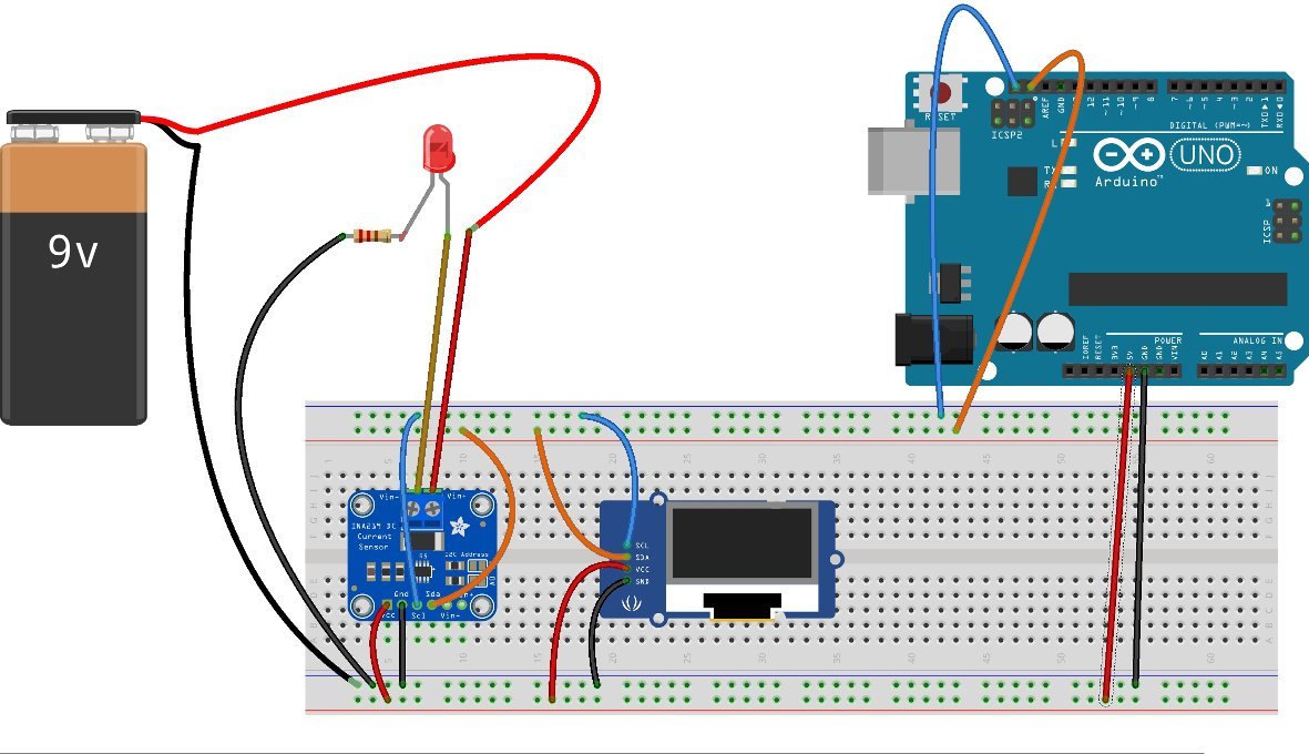
- Connect the power supply pins of Arduino i.e. 5 Volts and GND to power up the INA219 Current Module and the OLED module.
- Connect the SDA and SCL of both the modules to the Arduino ICSP2 Headers or A4 and A5 pins, respectively. Through the I2C protocol, the data will be communicated from the 1NA219 to the Arduino and then the information will be displayed on the OLED screen with the assistance of the same protocol.
- An LED is being used as an example Load for demonstration. Connect 9 Volts battery to power the Load. Connect the positive supply of the battery to VIN+ of the sensor and go to the shunt resistor and chip measures the potential drop.
- The Load is connected to the VIN- header and supplies voltage after passing through the shunt and load current is measured.
Arduino Code
// INA219 Current Sensor with OLED Display for Arduino Uno
//
// This sketch was modified from the Adafruit INA219 library example
//
// Gadget Reboot
//
// Required Libraries
// https://github.com/adafruit/Adafruit_INA219
// https://github.com/adafruit/Adafruit_SSD1306

#include <Wire.h>
#include <Adafruit_INA219.h>
#include <Adafruit_SSD1306.h>
Adafruit_INA219 ina219;

#define OLED_RESET 4
Adafruit_SSD1306 display(OLED_RESET);

float shuntvoltage = 0;
float busvoltage = 0;
float current_mA = 0;
float power_mW = 0;


void setup() {

  // initialize ina219 with default measurement range of 32V, 2A
  ina219.begin();

  // ina219.setCalibration_32V_2A();    // set measurement range to 32V, 2A  (do not exceed 26V!)
  // ina219.setCalibration_32V_1A();    // set measurement range to 32V, 1A  (do not exceed 26V!)
  // ina219.setCalibration_16V_400mA(); // set measurement range to 16V, 400mA

  // initialize OLED display
  display.begin(SSD1306_SWITCHCAPVCC, 0x3C);
  display.clearDisplay();
  display.setTextColor(WHITE);
  display.setTextSize(1);
  display.display();

}

void loop() {

  // read data from ina219
  shuntvoltage = ina219.getShuntVoltage_mV();
  busvoltage = ina219.getBusVoltage_V();
  current_mA = ina219.getCurrent_mA();
  power_mW = ina219.getPower_mW();

  // show data on OLED
  display.clearDisplay();

  display.setCursor(0, 0);
  display.print(busvoltage);
  display.print(" V");

  display.setCursor(50, 0);
  display.print(shuntvoltage);
  display.print(" mV");

  display.setCursor(0, 10);
  display.print(current_mA);
  display.print(" mA");

  display.setCursor(0, 20);
  display.print(power_mW);
  display.print(" mW");

  display.display();

}How Code Works?
The code can measure the Shunt voltage, Bus Voltage, Current, and Power of the load and display it on the SSD1306 OLED screen. The code will be explained with the help of snippets for clarity.
Inlcude Libraries and Header Files
First, we included the concerned libraries i.e. Adafruit_INA219 and Adafruit_SSD1306 for interfacing the INA219 Current Sensor module and the OLED display respectively. Then we created two objects i.e. ina219 to communicate with the INA219 Current Sensor module and OLED_RESET to OLED display. Variables are initialized to store the respective values.
#include <Wire.h>
#include <Adafruit_INA219.h>
#include <Adafruit_SSD1306.h>
Adafruit_INA219 ina219;

#define OLED_RESET 4
Adafruit_SSD1306 display(OLED_RESET);

float shuntvoltage = 0;
float busvoltage = 0;
float current_mA = 0;
float power_mW = 0;
Setup Block
The setup block will initialize the INA219 Current Sensor and calibrated up to the limit provided. We cannot exceed more than 26 Volts due to designed ratings. It initializes the OLED display too.
void setup() {

  // initialize ina219 with default measurement range of 32V, 2A
  ina219.begin();

  // ina219.setCalibration_32V_2A();    // set measurement range to 32V, 2A  (do not exceed 26V!)
  // ina219.setCalibration_32V_1A();    // set measurement range to 32V, 1A  (do not exceed 26V!)
  // ina219.setCalibration_16V_400mA(); // set measurement range to 16V, 400mA

  // initialize OLED display
  display.begin(SSD1306_SWITCHCAPVCC, 0x3C);
  display.clearDisplay();
  display.setTextColor(WHITE);
  display.setTextSize(1);
  display.display();

}
Inside loop
The main loop will just show the values on the OLED screen that are received by the Arduino through the chip by the inter-integrated interface and further transferred to the OLED screen for display.
// read data from ina219
  shuntvoltage = ina219.getShuntVoltage_mV();
  busvoltage = ina219.getBusVoltage_V();
  current_mA = ina219.getCurrent_mA();
  power_mW = ina219.getPower_mW();

  // show data on OLED
  display.clearDisplay();

  display.setCursor(0, 0);
  display.print(busvoltage);
  display.print(" V");

  display.setCursor(50, 0);
  display.print(shuntvoltage);
  display.print(" mV");

  display.setCursor(0, 10);
  display.print(current_mA);
  display.print(" mA");

  display.setCursor(0, 20);
  display.print(power_mW);
  display.print(" mW");

  display.display();
Code Output
As soon as the circuit is powered up, the Current Sensor will measure the shunt voltage, bus voltage, current, and power of the load. The data will be communicated to the controller. The Arduino yet again using the I2C protocol transmits the information to the SSD1306 OLED and we see the measurements displayed on the screen. The measurements can be cross-checked using a digital multimeter.
INA219 Alternative Options
- ACS712 Current Sensor Module – 20A
Applications
- Welding Equipment
- Communication Systems
- Power Control
- Servers
- Electronic Multimeters
- Mobiles Chargers
2D Diagram
INA219 Current Sensor Module comes in two packages i.e. DCN Package 8-Pin SOT-23 and D Package 8-Pin SOIC. The following figure depicts the 2d model of the 8-Pin SOIC D Package. It shows us the physical dimensions in millimeters required when a PCB card is designed.
Related Articles:
- AC Voltage measurement using PIC16F877A microcontroller
- Alternating Current Measurement using Pic Microcontroller
- ac current measurement using acs712 hall effect current sensor and Arduino
- Acs712 current sensor interfacing with Arduino for ac and dc current measurement
- AC Voltage Measurement using Arduino – Difference Amplifier Technique
- DC Voltmeter with Pic microcontroller
- DC Ammeter with Pic microcontroller
- Wattmeter with Pic microcontroller