In this Arduino tutorial, we will learn how to control LEDs using an IR remote and Arduino. This guide will focus on IR communication and also how to interface the IR receiver with Arduino to receive IR signals from IR Remote and consequently control LEDs based on the received signal from the remote. For demonstration purposes, we will control 5mm LEDs with the IR remote.
IR receiver is interfaced with Arduino to receive IR commands from the IR remote. Arduino will receive these commands and take action accordingly.
We have another article in which we learned how to use an IR transmitter and IR receiver with Arduino.

IR Communication
Infrared Communication is a very easy-to-use, inexpensive and common way of wireless communication. IR radiation is basically a light that cannot be seen by the human eye. The IR LED detects and works at 980 nm (nanometer), that’s considered near to infra-red. As it is undetectable to human eye, it is perfect for wireless communication. IR radiations are everywhere, these emit from sun, light bulbs and many other things.
IR light (Transmitter) is almost similar to visible light except its wavelength is longer. When you hit a TV remote button, IR Led transmit information to the TV. IR Led turns on and off 38000 times a second to transmit information to IR receiver in TV.
IR Signal
The IR signal is looking infra-red that’s flashing turn ON and OFF 38,500 time per second that means IR light is undetectable to the human eye.
Important Concepts
- Pulse Width Modulation (PWM)
The IR detector sends low pulses that can be measured to determine what information the IR remote is sending, it’s an example of using PWM for communication.
- Carrier signal
The IR remote uses a 38,500 remote signal to transmit the pulse durations.
IR Receiver Module
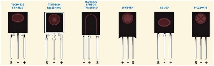
The IR receiver is used to receive the infrared rays that are emitted by IR emitter. The module consists of an IR receiver. The IR receiver is of many types, some are shown below
IR receiver modules usually come with three pins:
- Signal
- +V
- GND
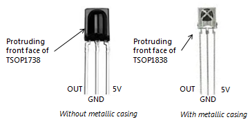
The IR receiver (TSOP1838) which we will use in this tutorial is shown below

Specifications of IR Receiver Module
The IR Receiver Module has the following specifications
- Operating voltage of 2.7V to 5.5V
- Supply current of 0.4-1.5 mA
- Operating temperature from -25 C to 85 C
- Receiving a distance of 18 meter
- The frequency at which it operates is 37.9 kHz
Control LEDs Using IR Remote and Arduino
Required Hardware:
- Arduino Uno Board
- IR Receiver TSO1838
- IR Remote
- Three 220 ohm Resistors
- Three 5mm LEDs
Interfacing Infrared Receiver TSOP1838 and LEDs with Arduino
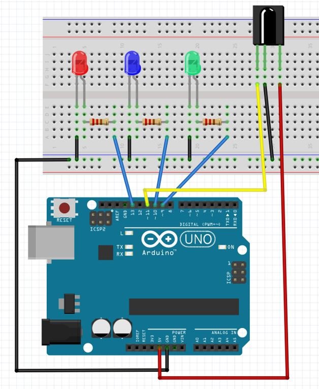
Arduino interfacing with IR sensor is very simple. It is like interfacing a Switch with the Arduino. Connect the 5V and ground of the Arduino to the VCC and GND pins of the IR receiver. Moreover, connect any digital pin of Arduino with the signal pin of the receiver module. In our case, we will use pin 11.
| IR Receiver | Arduino |
|---|---|
| IR Receiver | Arduino |
| Signal | Pin 11 |
| VCC | 5V |
| GND | GND |
The Red, Green and Blue Led is connected with digital pins of Arduino 13, 9 and 10 respectively. Connect digital pin of Arduino with the LED’s anode terminal through a 220 ohm current limiting resistor. Also, make sure to connect cathode terminal of the LED with the ground pin of the board. Check this tutorial on LED blinking using Arduino for more information.
Install IRremote Library
We will install IRremote library to receive and process IR signals This library is available in Arduino Library Manager.
Open your Arduino IDE. Go to Sketch > Include Library > Manage Libraries. Type ‘IRremote’ and press enter. Install the library shown below:

After installing all the libraries, restart your IDE.
Arduino Sketch
Open your Arduino IDE and go to File > New. A new file will open. Copy the code given below in that file and save it.
We will use an IR remote control to send data to the receiver module. This received data will be decoded and used to control the onboard LED of Arduino board connected at pin 13. When we will press ‘1’ from the remote, the LED will turn ON. When we will press ‘2’ from the remote, the will LED turn OFF.
#include<IRremote.h>    // Header file for IR remote

int receiver = 11;  Signal Pin of IR receiver to Arduino Digital Pin 11
int Redled= 13;   // initialize the Red Led on Digital Pin 13 of Arduino
int Greenled=9;   // initialize Green Led on Digital Pin 9 of Arduino
int Blueled=10;   // initialize Blue Led on Digital Pin 10 of Arduino

IRrecv irrecv(receiver);      // create exemplar of 'irrecv'
decode_results results;       // create exemplar of 'decode_results'

void setup()                 // Setup code which runs once time
{
  pinMode(Redled,OUTPUT);    // Define the pin of arduino for OUTPUT
  pinMode(Greenled,OUTPUT); // Define the pin of arduino for OUTPUT
  pinMode(Blueled,OUTPUT);   // Define the pin of arduino for OUTPUT
  Serial.begin(9600);                            // To Start Serial communication
  Serial.println("IR Receiver Button Decode");
  irrecv.enableIRIn();         // Start the receiver
}

void loop()                              //( LOOP: RUNS CONSTANTLY )
{
  if (irrecv.decode(&results)) // have we received an IR signal?
  {
    translateIR();
    irrecv.resume(); // receive the next value
  }
}

void translateIR() // takes action based on IR code received
// describing Remote IR codes
{
  switch(results.value)
  {
// Define the IR Remote
  case 0xFFA25D: Serial.println(" POWER");break;
  case 0xFF629D: Serial.println(" STOP");break;
  case 0xFFE21D: Serial.println(" MUTE");break;
  case 0xFF22DD: Serial.println(" MODE");break;
  case 0xFF02FD: Serial.println(" REVERSE");break;
  case 0xFFC23D: Serial.println(" EQ");break;
  case 0xFFE01F: Serial.println(" PREVIOUS");break;
  case 0xFFA857: Serial.println(" NEXT");break;
  case 0xFF906F: Serial.println(" FORWARD");break;
  case 0xFF6897: Serial.println(" INCREASE");break;
  case 0xFF9867: Serial.println(" DECREASE");break;
  case 0xFFB04F: Serial.println(" 0");

  digitalWrite(Redled,LOW);
  digitalWrite(Greenled,LOW);
  digitalWrite(Blueled,LOW);
  break;
  case 0xFF30CF: Serial.println(" 1");
  digitalWrite(Redled,HIGH);break;
  case 0xFF18E7: Serial.println(" 2");
  digitalWrite(Greenled,HIGH);break;
  case 0xFF7A85: Serial.println(" 3");
  digitalWrite(Blueled,HIGH);break;
  case 0xFF10EF: Serial.println(" 4");    break;
  case 0xFF38C7: Serial.println(" 5");    break;
  case 0xFF5AA5: Serial.println(" 6");    break;
  case 0xFF42BD: Serial.println(" 7");    break;
  case 0xFF4AB5: Serial.println(" 8");    break;
  case 0xFF52AD: Serial.println(" 9");    break;
  case 0xFFFFFFFF: Serial.println(" REPEAT");break;
  default:
    Serial.println(" other button   ");
  }// End Case

  delay(500); // Do not get immediate repeat
  }
How does the Code Works?
Firstly, include the IRremote library that we just installed.
#include <IRremote.h>Next, specify the Arduino digital pin connected with the receiver module’s signal pin. It is pin 11 in our case.
int receiver = 11;As we want to control the LEDs, hence we will specify the pins they are connected to. In the following lines we have defined int variables called ‘Redpin’, ‘Greenled’ and ‘Blueled’ set at 13, 9 and 10.
int Redled= 13;   // initialize the Red Led on Digital Pin 13 of Arduino
int Greenled=9;   // initialize Green Led on Digital Pin 9 of Arduino
int Blueled=10;   // initialize Blue Led on Digital Pin 10 of Arduino
The next important step is to create an object called irrecv() that takes in the receiver pin as a parameter inside it.
IRrecv irrecv(receiver); Moreover, we will create another object called results of the decode_results class. This will be used later on in the code to manage the decoded data.
decode_results results; Inside the setup() function, we start the IR receiver by using irrecv.enableIRIn(). We will configure the red, green and blue LED pins as output pins. Also, open the serial communication at a baud rate of 9600 and print ‘IR Receiver Button Decode’ in the serial monitor.
void setup()                 // Setup code which runs once time
{
  pinMode(Redled,OUTPUT);    // Define the pin of arduino for OUTPUT
  pinMode(Greenled,OUTPUT); // Define the pin of arduino for OUTPUT
  pinMode(Blueled,OUTPUT);   // Define the pin of arduino for OUTPUT
  Serial.begin(9600);                            // To Start Serial communication
  Serial.println("IR Receiver Button Decode");
  irrecv.enableIRIn();         // Start the receiver
}
Inside the loop() function, we will first check if decoded information is available or not (in our case when a remote key is being pressed). This gets stored in ‘results.value’. Then if key ‘1’ is pressed, we will turn the red LED on. If key ‘2’ is pressed we will turn the green LED on. Likewise, if key ‘3’ is pressed, we will turn the blue led on. If key ‘0’ is pressed then all LEDs will turn off. After that we will use irrecv.resume() so that the IR receiver resets.
Note: You will have to find the corresponding codes for each key for this to work properly.
void loop() //( LOOP: RUNS CONSTANTLY )
{
if (irrecv.decode(&results)) // have we received an IR signal?
{
translateIR();
irrecv.resume(); // receive the next value
}
}
void translateIR() // takes action based on IR code received
// describing Remote IR codes
{
switch(results.value)
{
// Define the IR Remote
case 0xFFA25D: Serial.println(" POWER");break;
case 0xFF629D: Serial.println(" STOP");break;
case 0xFFE21D: Serial.println(" MUTE");break;
case 0xFF22DD: Serial.println(" MODE");break;
case 0xFF02FD: Serial.println(" REVERSE");break;
case 0xFFC23D: Serial.println(" EQ");break;
case 0xFFE01F: Serial.println(" PREVIOUS");break;
case 0xFFA857: Serial.println(" NEXT");break;
case 0xFF906F: Serial.println(" FORWARD");break;
case 0xFF6897: Serial.println(" INCREASE");break;
case 0xFF9867: Serial.println(" DECREASE");break;
case 0xFFB04F: Serial.println(" 0");
digitalWrite(Redled,LOW);
digitalWrite(Greenled,LOW);
digitalWrite(Blueled,LOW);
break;
case 0xFF30CF: Serial.println(" 1");
digitalWrite(Redled,HIGH);break;
case 0xFF18E7: Serial.println(" 2");
digitalWrite(Greenled,HIGH);break;
case 0xFF7A85: Serial.println(" 3");
digitalWrite(Blueled,HIGH);break;
case 0xFF10EF: Serial.println(" 4"); break;
case 0xFF38C7: Serial.println(" 5"); break;
case 0xFF5AA5: Serial.println(" 6"); break;
case 0xFF42BD: Serial.println(" 7"); break;
case 0xFF4AB5: Serial.println(" 8"); break;
case 0xFF52AD: Serial.println(" 9"); break;
case 0xFFFFFFFF: Serial.println(" REPEAT");break;
default:
Serial.println(" other button ");
}// End Case
delay(500); // Do not get immediate repeat
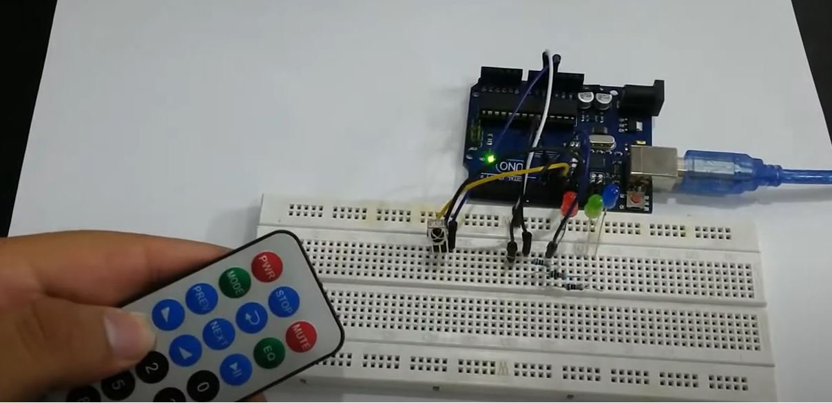
}Demonstration
To see the demonstration of the above code, upload the code to Arduino. But, before uploading code, make sure to select the Arduino board from Tools > Board and also select the correct COM port to which the Arduino board is connected from Tools > Port.

Once the code is uploaded to Arduino, open the serial monitor and set the baud rate to 9600. Now press key 1 and the red led will turn on. Press key 2 and the green led will turn on. Press key 3 to turn the blue LED on. Now press key 0 to turn all the LEDs off.
Watch the video demonstration below:
You may also like to read: