PWM using Pic Microcontroller with Examples, In this tutorial, you will learn to generate a PWM signal with the help of PIC microcontroller (PIC16F877A). We will provide pulse width modulation examples with MikroC and MPLAB XC8 compiler. If PWM is supposed to be a new concept for the beginner, then by the end of the tutorial, you will have a sound knowledge of this term and will be able to work with it in different projects.
What is pulse width modulation?
PWM (Pulse Width Modulation) is a powerful technique used to control analog circuits with the digital output from the microcontroller. There are two major components of a PWM signal that defines its behavior; PWM duty cycle, time period and frequency.

PWM Duty cycle
It describes the ‘on-time’ of a signal. An on-time is the duration of a signal for which the signal stays HIGH. Duty cycle is measured in percentage. For example, if a digital signal is on for half of the time duration and off for the other half, the digital signal is said to have a duty cycle of 50%. Similarly, if a signal stays high for a longer period of time than it stays low, the signal will have a duty cycle greater than 50%.
Time Period or Frequency
The frequency determines the amount of time taken by PWM to complete one cycle. For example, a frequency of 1000Hz would mean 1000 cycles completed per second. Before using PWM module of Pic microcontroller, we should define the frequency/timer period of the signal.
PWM using PIC Microcontroller
Now you know the basics of pulse width modulation and you also know its related terminology. Now let’s start understanding how to generate different frequency and duty cycle digital signals using PIC16F877A microcontroller.
Although, we use PIC16F877A in this post, but you can easily apply the same concepts and examples to other PIC microcontrollers also. As mentioned earlier, we will discuss an example with two compilers, namely, MPLAB XC8 and MikroC Pro. First let’s begin with MikroC for PIC compiler.
PIC16F877A PWM Examples using MikroC
To generate PWM with the help of a PIC16F877A microcontroller, built-in CCP modules are used. CCP stands for Capture/Compare/PWM. There are two CCP modules present in PIC16F877A; CCP1 and CCP2 at pins RC2 and RC1 respectively.
MikroC for PIC provides built-in libraries for to generate PWM with variables frequency and variable duty cycle.
MikroC for PIC PWM Library
As mentioned earlier, MikroC provides a built-in library for pulse width modulation module of pic microcontroller. This library is generic and can be used with all PIC16F, PIC18 series microcontrollers. These are the four functions that are used to generate PWM, set frequency and change duty cycle.
- PWMx_Init
PWMx_Init(long frequency) function used to set/declare frequency of signal. The input parameter to this function is required frequency. Here x denotes the number of CCP module. Because some pic microcontrollers come in more than one CCP modules. For instance, PIC16F877A microcontroller has two CCP modules CCP1 and CCP2.
For example, we want to use CCP1 module andwant set frequency of 5000Hz or 5KHz. we initialize this routine like this:
PWM1_Init(5000);  //initialize CCP1 module with frequency 5kHz
PWM2_Init(5000);  //initialize CCP2 module with frequency 5kHz
- PWMx_Set_Duty(unsigned int duty_cycle)
PWMx_Set_Duty() function defines the duty cycle of PWM. The input parameter to this function is a duty cycle. The duty cycle value can be any number between 0-255. Here ‘0’ means 0%, 127 means 50% and 255 means 100% duty cycle. But we can adjust the duty cycle to any percentage with this formula:
duty_cycle = (pecentage x 255 ) /100
- PWMx_Start(): This routine starts the PWM module and after calling this function, you can see output on CCP1 and CCP2 pins.
- PWMx_Stop(): If you can this function, it will stop the pic microcontroller from outputting signal on CCP1 and CCP2 pins.
Generate Fix Duty Cycle PWM using PIC16F877A
In this example, we will see how to generate a fix duty cycle PWM signal using PIC16F877A microcontroller. In this circuit, we connected a 16×2 LCD with PIC16F877A and used the CCPI module to get an output signal ( from RC2 pin).
If you don’t know how to interface LCD with PIC16F877A microcontroller, read this post:

Fix Duty Cycle PWM Programming
First of all, we need to define which PORT of PIC16F877A connected with LCD. PORTB pins RB2-RB7 are used and these lines declare pins.
// LCD Module connections
sbit LCD_RS at RB2_bit;
sbit LCD_EN at RB3_bit;
sbit LCD_D7 at RB7_bit;
sbit LCD_D6 at RB6_bit;
sbit LCD_D5 at RB5_bit;
sbit LCD_D4 at RB4_bit;
// End LCD module connections

// LCD Pin direction
sbit LCD_RS_Direction at TRISB2_bit;
sbit LCD_EN_Direction at TRISB3_bit;

sbit LCD_D7_Direction at TRISB7_bit;
sbit LCD_D6_Direction at TRISB6_bit;
sbit LCD_D5_Direction at TRISB5_bit;
sbit LCD_D4_Direction at TRISB4_bit;
// End of LCD Pin direction
Inside the main function, we always initialize variables, define GPIO pins settings and peripherals initialization. This line set sets PORTC as an output PORT using TRISC register ( TRISC is a direction control register).
TRISC = 0x00; // PORTC as output
As mentioned earlier, before using the PWM library, we need to initialize frequency and call pwm_start function. PWM1_Init(5000) initialize the CCPI module with the frequency of 5KHz and PWM1_Start() enables the module and enables functionality on RC2 pin of PIC16F877A microcontroller.
PWM1_Init(5000); // Initialize PWM1
PWM1_Start(); // start PWM1
These lines initialize 16×2 LCD according to pins connection setting defines above.
Lcd_Init(); // Initialize LCD
Lcd_Cmd(_LCD_CLEAR); // Clear Display
Lcd_Cmd(_LCD_CURSOR_OFF); // Cursor Off
While(1) function will keep executing repeatedly and performs tasks defined inside this routine. First, it prints string on LCD that states duty_cycle in percentage. After that PWM1_Set_Duty(63) function produces a signal on the RC2 pin with a 25% duty cycle.
Lcd_Out(1,1,"25% Duty Cycle");// Write “25% Duty Cycle” in the first row
PWM1_Set_Duty(63); //Change the duty cycle
Delay_ms(1000);
Proteus Simulation and hardware results
Complete Code
// LCD Module connections
sbit LCD_RS at RB2_bit;
sbit LCD_EN at RB3_bit;
sbit LCD_D7 at RB7_bit;
sbit LCD_D6 at RB6_bit;
sbit LCD_D5 at RB5_bit;
sbit LCD_D4 at RB4_bit;
// End LCD module connections

// LCD Pin direction
sbit LCD_RS_Direction at TRISB2_bit;
sbit LCD_EN_Direction at TRISB3_bit;

sbit LCD_D7_Direction at TRISB7_bit;
sbit LCD_D6_Direction at TRISB6_bit;
sbit LCD_D5_Direction at TRISB5_bit;
sbit LCD_D4_Direction at TRISB4_bit;
// End of LCD Pin direction
void main()
{

TRISC = 0x00; // PORTC as output
PWM1_Init(5000); // Initialize PWM1
PWM1_Start(); // start PWM1

Lcd_Init(); // Initialize LCD
Lcd_Cmd(_LCD_CLEAR); // Clear Display
Lcd_Cmd(_LCD_CURSOR_OFF); // Cursor Off

while (1) // endless loop
{


Lcd_Out(1,1,"25% Duty Cycle");// Write “25% Duty Cycle” in the first row
PWM1_Set_Duty(63); //Change the duty cycle
Delay_ms(1000);

Lcd_Out(1,1,"50% Duty Cycle");// Write "50% Duty Cycle" in the first row
PWM1_Set_Duty(127); //Change the duty cycle
Delay_ms(1000);

Lcd_Out(1,1,"75% Duty Cycle");// Write “"75% Duty Cycle" in the first row
PWM1_Set_Duty(190); //Change the duty cycle
Delay_ms(1000);

Lcd_Out(1,1,"100% Duty Cycle");// Write "100% Duty Cycle"in the first row
PWM1_Set_Duty(255); //Change the duty cycle
Delay_ms(1000);
}
}
Variable Duty Cycle PWM using PIC Microcontroller
In this PWM example, we will learn to generate a variable duty cycle pulse width modulation signal using pic16f877a. We use two push buttons for each PWM channel. One push button increases the duty cycle and the other push-button decreases it.
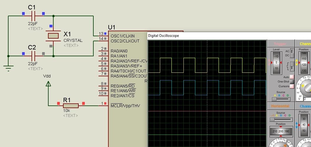
Variable Duty Cycle PWM Circuit Diagram
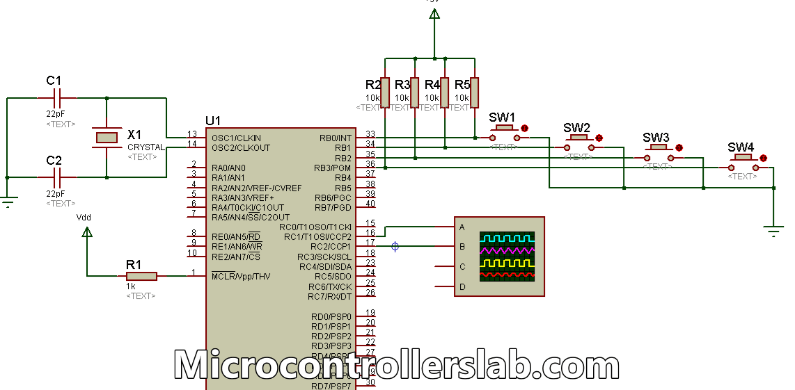
Make the above circuit diagram in Proteus. Four switches (SW1, SW2, SW3, and SW4) are connected to the lower four bits of PORTB of the controller with pull-up resistors of 10K. The other ends of the switches are grounded. These switches are used to control the duty ratio of PWM which is generated by the CCP modules.
An oscilloscope has been connected to the CCP1 and CCP2 pins of the microcontroller which is used to display the waveforms and variations in it, as the duty cycle is increased or decreased. The remaining standard circuit includes the crystal oscillator connection and that of the MCLR pin.
Programming
Write the following code in mikroC compiler:
void main()
{
short current_duty_1 = 16; // initial value for current_duty_1
short current_duty_2 = 16; // initial value for current_duty_2

TRISB = 0xFF; // PORTB as input
TRISC = 0x00; // PORTC as output

PWM1_Init(5000); // Initialize PWM1
PWM2_Init(5000); // Initialize PWM2

PWM1_Start(); // start PWM1
PWM2_Start(); // start PWM2

PWM1_Set_Duty(current_duty_1); // Set current duty for PWM1
PWM2_Set_Duty(current_duty_2); // Set current duty for PWM2

while (1) // endless loop
{
if (!RB0_bit) // SW1 is pressed
{
Delay_ms(40);
current_duty_1++; // increment current_duty_1
PWM1_Set_Duty(current_duty_1); //Change the duty cycle
}

if (!RB1_bit) // SW2 is pressed
{
Delay_ms(40);
current_duty_1--; // decrement current_duty_1
PWM1_Set_Duty(current_duty_1);
}

if (!RB2_bit) // SW3 is pressed
{
Delay_ms(40);
current_duty_2++; // increment current_duty_2
PWM2_Set_Duty(current_duty_2);
}

if (!RB3_bit) // SW4 is pressed
{
Delay_ms(40);
current_duty_2--; // decrement current_duty_2
PWM2_Set_Duty(current_duty_2);
}

Delay_ms(10); // slow down change pace a little
}
}
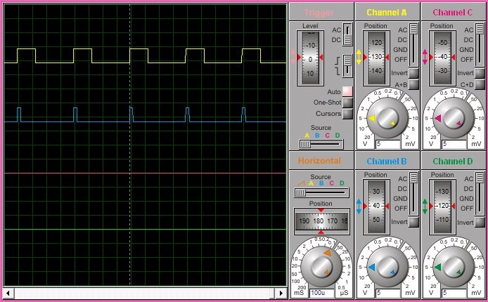
Simulation Result
The figure below shows the resulting waveforms received from the two CCP modules. CCP2 pin of the controller is connected to the channel ‘A’ (yellow) of the oscilloscope and CCP1 pin to channel ‘B’ (blue). The PWM duty ratio, generated from the CCP2 pin, has been increased via switch SW3.

Code Working
This code uses many built-in library functions of PWM present in the mikroC Compiler. The initial value of the duty cycle has been declared at the beginning of the code. PORTB is set as an input port on which the switches are connected. PORTC is set as an output port for generating PWM signals. The four ‘if’ statements determine the state of the two waveforms. If switch SW1 is pressed, the duty ratio of PWM produced by CCP1 is increased and if SW2 is pressed, the duty ratio produced by CCP1 is decreased. Similarly, for the CCP2 module, SW3 increases the PWM duty ratio and SW4 decreases the PWM duty ratio.
Use ADC value to Control PWM using PIC Microcontroller
There are many applications where we want to change the duty cycle by using ADC of PIC microcontroller. For instance, you can want to control dc motor speed with the help knob or variable resistor. In this case, we can measure the voltage across the variable resistor with the help ADC of PIC microcontroller and map this value to the duty cycle of the PWM signal.
If you don’t know how to use ADC of PIC microcontroller, read this tutorial:
ADC with PWM Circuit
As you can see in this circuit, we connect a 10kohm variable resistor with ADC channel 2 of PIC16F877A. Connect one end of POT with 5 volts and another end with the ground. The analog voltage across 10k variable resistor is used measured with ADC and the value of analog voltage is used as a duty cycle for Pwm_Duty_Cyle function.
LCD is used to display Duty_Cycle value in percentage. Connect LCD with PIC16F877A PORTB and make pin connections like this:
- RB2 >> RS
- RB3 >> E
- RB4 >> D4
- RB5 >> D5
- RB6 >> D6
- RB7 >> D7
ADC with PWM Code
Upload this code to PIC16F877A microcontroller and select external oscillator and frequency of 8MHz.
sbit LCD_RS at RB2_bit;
sbit LCD_EN at RB3_bit;
sbit LCD_D4 at RB4_bit;
sbit LCD_D5 at RB5_bit;
sbit LCD_D6 at RB6_bit;
sbit LCD_D7 at RB7_bit;
sbit LCD_RS_Direction at TRISB2_bit;
sbit LCD_EN_Direction at TRISB3_bit;
sbit LCD_D4_Direction at TRISB4_bit;
sbit LCD_D5_Direction at TRISB5_bit;
sbit LCD_D6_Direction at TRISB6_bit;
sbit LCD_D7_Direction at TRISB7_bit;

unsigned char ch;
unsigned int adc_rd;
unsigned int division;
char *text;
long tlong;

void main()
{

INTCON = 0;
TRISA = 0x04;
TRISC = 0;
PORTC = 0;
PWM1_Init(10000);
Lcd_Init();
Lcd_Cmd(_LCD_CURSOR_OFF);
Lcd_Cmd(_LCD_CLEAR);
text = "ADC PWM";
Lcd_Out(1,1,text);
text = "Cycle_Duty:";
Lcd_Out(2,1,text);
ADCON1 = 0x82;
Delay_ms(2000);
PWM1_Start();

while (1)
{
adc_rd = ADC_Read(2);
Delay_ms(5);
tlong = (long)adc_rd * 255;
tlong = tlong / 1023;
tlong = (tlong * 100)/255; //convert into percentage
ch = tlong/100;
Lcd_Chr(2,12,48+ch);
ch = (tlong / 10) % 10;
Lcd_Chr_CP(48+ch);
ch = tlong % 10;
Lcd_Chr_CP(48+ch);
division = adc_rd/4;
PWM1_Set_Duty(division);
Delay_ms(100);
}
}
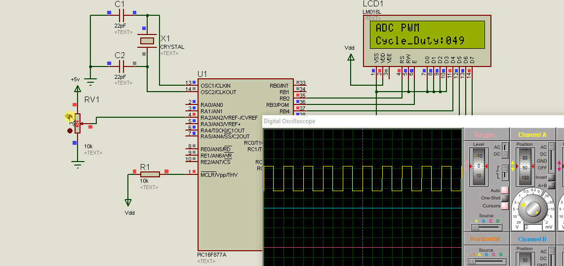
Simulation Result Proteus
As you can see from this proteus simulation result as soon as we change the variable resistor know duty cycle is increasing or decreasing according to the direction of the Knob. If we move a knob towards 5 volts terminal, the voltage starts increasing on AN0 pin and so is the duty cycle. Because we write the program with this setting.
PWM Applications
PWM can be used in a variety of applications.
- DC Motor Speed Control
- It can be used to control a servo motor as well as other motors requiring speed control.
- AC Dimmer Voltage Control
- PWM is also used to control the average power delivered to a load.
Generate PWM Using PIC Microcontroller with MPLAB XC8 Compiler
In this section, we will see how to write a program for PWM generation in MPLAB XC8 compiler using PIC16F877A microcontroller. As you know that MPLAB generally does not provide libraries for all built-in peripherals of pic microcontrollers such as the PWM library. Especially, PIC16F877A libraries are not available in this compiler. Therefore, we have to write the code from register levels of CCP1 and CCP2 modules.
These are the registers that used to configure CCP1 and CCP2 modules of PIC16F877A microcontroller.
- CCP1CON
- CCP2CON
- TMR1L: TMR1H
- T1CON
- T2CON
- PR2
- CCPR1L: CCPR1H
- CCPR2L: CCPR2H
How to set time Period/Frequency
First, let see how to set the PWM time period or frequency using these configuration registers of CCP1 and CCP2 modules. We calculate PWM period by using this formula:
PWM Period = [(PR2) + 1] x 4 x TOSC x (TMR2 Prescale Value)
In this formula, the only unknown is the PR2 register value. But we can calculate PR2 value for a required PWM_Period. For example, we rewrite this formula like this:
PR2 = (PWM_Period / (4 x Tosc x TMR2 Prescale )) - 1
As you know time period is inverse of frequency. Tosc is a time period of the oscillator. Hence we can write both terms like this also:
_XTAL_FREQ = 1/Tosc
PWM_Period = 1/PWM_Frquency
Therefore, we can write RP2 register value equation like this:
PR2 = (_XTAL_FREQ/ (PWM_Frquency x 4 x TMR2PRESCALE)) – 1;
In summary, we can set frequency using the above formula for both PWM channels. Because all other terms are known such as oscillator frequency, TMR2PRESCALE and required frequency value. These two functions initialize frequency for CCPI and CCP2 modules:
#define _XTAL_FREQ 8000000
#define TMR2PRESCALE 4
void PWM1_init(long freq)
{
  PR2 = (_XTAL_FREQ/(freq*4*TMR2PRESCALE)) - 1;
}

void PWM2_init(long freq)
{
  PR2 = (_XTAL_FREQ/(freq*4*TMR2PRESCALE)) - 1;
}
How to Set Duty Cycle?
CCPR1L and CCP1CON<5:4> registers are used to define the duty cycle of the PWM signal. Because PIC16F877A microcontroller PWM provides 10-bit resolution. But the CCPR1L register is only 8-bit wide. Therefore, the eight most significant bits store in CCPR1L and two LSB in CCPxX: CCPxY bits of CCP1CON register. Similarly for CCP2 module CCP2CON registers, bit4 and bit5 are used. The following equation defines duty_cycle:
PWM_Duty_Cycle =(CCPR1L:CCP1CON<5:4>) x TOSC x (TMR2_Prescale_Value)These functions are used to set the duty cycle of both PWM channels of PIC16F877A microcontroller.
int PWM_Max_Duty()
{
  return(_XTAL_FREQ/(frequency*TMR2PRESCALE));
}

void PWM1_Set_duty(unsigned int duty)
{
    duty = ((float)duty/100) * 1023; //percentage;
  if(duty<1024)
  {
    duty = ((float)duty/1023)*PWM_Max_Duty();
    CCP1CONbits.CCP1X = duty & 0x02;
    CCP1CONbits.CCP1Y = duty & 0x01;
    CCPR1L = duty>>0x02;
  }

  }

void PWM2_Set_duty(unsigned int duty)
{
    duty = ((float)duty/100) * 1023; //percentage;
  if(duty<1024)
  {
    duty = ((float)duty/1023)*PWM_Max_Duty();
    CCP2CONbits.CCP2X = duty & 0x02;
    CCP2CONbits.CCP2Y = duty & 0x01;
    CCPR2L = duty>>0x02;
  }
}
Start and Stop PWM
TO start and stop PWM function on RC2 and RC1 pins of PIC16F877A microcontroller, timer2 should be enabled with T2CON registers and also must configure CCP1CON register for PWM operation by setting CCPxM3: CCPxM0 to active high. This function enables PWM1 of the RC2 pin.
void PWM1_start()
{
  CCP1CONbits.CCP1M3 = 1;  // select PWM_Mode
  CCP1CONbits.CCP1M2 = 1;  // select PWM_Mode

  #if TMR2PRESCALAR == 1
    T2CONbits.T2CKPS0 = 0;
    T2CONbits.T2CKPS1 = 0;
  #elif TMR2PRESCALAR == 4
    T2CONbits.T2CKPS0 = 1;
    T2CONbits.T2CKPS1 = 0;
  #elif TMR2PRESCALAR == 16
    T2CONbits.T2CKPS0 = 1;
    T2CONbits.T2CKPS1 = 1;
  #endif

  T2CONbits.TMR2ON = 1;  // turn_on timer2
  TRISC2 = 0;          // Configure RC2 as a digital output
}
PWM1_stop function disable output on RC2 and CCP1 module.
PWM1_stop()
{
  CCP1CONbits.CCP1M3 = 0;  //disable CCP1_PWM_Mode
  CCP1CONbits.CCP1M2 = 0;  //disable CCP1_PWM_Mode
}
Similary these tw routines used to start and stop PWM2 by enabling or disabling CCP2 module.
PWM2_start()
{
  CCP2CONbits.CCP2M3 = 1;
  CCP2CONbits.CCP2M2 = 1;

   // if TMR2PRESCALAR == 1 uncomment these two
    //T2CKPS0 = 0;
    //T2CKPS1 = 0;
  //For TMR2PRESCALAR == 4
    T2CONbits.T2CKPS0 = 1;
    T2CONbits.T2CKPS1 = 0;
  //if TMR2PRESCALAR == 16  uncomment these two
    //T2CKPS0 = 1;
    //T2CKPS1 = 1;

    T2CONbits.TMR2ON = 1;
    TRISC1 = 0;
}

PWM2_stop()
{
  CCP2CONbits.CCP2M3 = 0;
  CCP2CONbits.CCP2M2 = 0;
}
PWM Generation Example MPLAB XC8 Compiler
This simple example generates 50% duty cycle signals on RC1 and RC2 pins of PIC16F877A microcontroller.
PWM Code PIC16F877A MPAB XC8 Compiler
#include <xc.h>
#define _XTAL_FREQ 8000000
#define TMR2PRESCALE 4
long frequency;

int PWM_Max_Duty()
{
  return(_XTAL_FREQ/(frequency*TMR2PRESCALE));
}

void PWM1_init(long freq)
{
  PR2 = (_XTAL_FREQ/(freq*4*TMR2PRESCALE)) - 1;
  frequency = freq;
}

void PWM2_init(long freq)
{
  PR2 = (_XTAL_FREQ/(freq*4*TMR2PRESCALE)) - 1;
  frequency = freq;
}

void PWM1_Set_duty(unsigned int duty)
{
    duty = ((float)duty/100) * 1023; //percentage;
  if(duty<1024)
  {
    duty = ((float)duty/1023)*PWM_Max_Duty();
    CCP1CONbits.CCP1X = duty & 0x02;
    CCP1CONbits.CCP1Y = duty & 0x01;
    CCPR1L = duty>>0x02;
  }

  }

void PWM2_Set_duty(unsigned int duty)
{
    duty = ((float)duty/100) * 1023; //percentage;
  if(duty<1024)
  {
    duty = ((float)duty/1023)*PWM_Max_Duty();
    CCP2CONbits.CCP2X = duty & 0x02;
    CCP2CONbits.CCP2Y = duty & 0x01;
    CCPR2L = duty>>0x02;
  }
}

void PWM1_start()
{
  CCP1CONbits.CCP1M3 = 1;
  CCP1CONbits.CCP1M2 = 1;

  #if TMR2PRESCALAR == 1
    T2CONbits.T2CKPS0 = 0;
    T2CONbits.T2CKPS1 = 0;
  #elif TMR2PRESCALAR == 4
    T2CONbits.T2CKPS0 = 1;
    T2CONbits.T2CKPS1 = 0;
  #elif TMR2PRESCALAR == 16
    T2CONbits.T2CKPS0 = 1;
    T2CONbits.T2CKPS1 = 1;
  #endif

  T2CONbits.TMR2ON = 1;
  TRISC2 = 0;
}

PWM1_stop()
{
  CCP1CONbits.CCP1M3 = 0;
  CCP1CONbits.CCP1M2 = 0;
}

PWM2_start()
{
  CCP2CONbits.CCP2M3 = 1;
  CCP2CONbits.CCP2M2 = 1;

   // if TMR2PRESCALAR == 1 uncomment these two
    //T2CKPS0 = 0;
    //T2CKPS1 = 0;
  //For TMR2PRESCALAR == 4
    T2CONbits.T2CKPS0 = 1;
    T2CONbits.T2CKPS1 = 0;
  //if TMR2PRESCALAR == 16  uncomment these two
    //T2CKPS0 = 1;
    //T2CKPS1 = 1;

    T2CONbits.TMR2ON = 1;
    TRISC1 = 0;
}

PWM2_stop()
{
  CCP2CONbits.CCP2M3 = 0;
  CCP2CONbits.CCP2M2 = 0;
}


void main(void)
{
    TRISC=0x00;
    PWM1_init(5000);
    PWM1_start();
    PWM2_init(5000);
    PWM2_start();
    while(1)
    {
     PWM1_Set_duty(50);
     PWM2_Set_duty(50);
    }
    return;
}
You can also use examples given in MikroC for PIC section above with MPLAB XC8 compiler also. Because concepts will remain the same. You will only need to add MPLAB PWM functions in the code. But the rest of the code will remain the same.
How do i generate pwm signal, if i am using buck boost application? from the above i do understand the concepts, but for buck boost which have 3 switch and the dual output?
Practical writing , I am thankful for the specifics – Does anyone know if my company might acquire a fillable a form example to fill in ?
I want to control pwm output of pic16f877a by output voltage instead of switches. is that possible .please help me.
Thanks
hi, Malik!
please send mikroc code this project.
tanks, Steve.
Aoa, did you find the mikro c code for generating pwm through adc read? if you have find that can you plz help me with this.
hi Malik!
sorry, not code, only PWM Article files.
Thanks, Steve,
How to set configuration bits of a pic16f877a to generate PWM
Thank you for project!
Link to files is not valid 🙁
Anybody send me files please.
I want code for ( PICAXE 18M2 Microcontroller PWM Motor Speed Control )