This tutorial is designed for beginners who are new to the world of Microcontrollers, to provide a little know-how about the technology. PIC (Peripheral Interface Controller) family is popular among students, hobbyists and also industrial developers due to its low cost, serial programming capability and its ease of availability. The 8-bit PIC microcontrollers are divided into four large families based on their built-in special features:
- PIC10FXXX series
- PIC12FXXX series
- PIC16FXXX series
- PIC18FXXX series
Recommended Components
The following components are used in this project or are helpful for building it with a PIC microcontroller.
| Component | How it’s used in this project | Buy on Amazon |
|---|---|---|
| PIC16F877A microcontroller | The 40-pin PIC used throughout this getting-started guide. | Check Price |
| PICkit 5 programmer/debugger | Programs and debugs the PIC16F877A during your first projects. | Check Price |
| Breadboard | Hosts the PIC with its reset and oscillator circuit for prototyping. | Check Price |
| Jumper Wires | Connects power, ground, oscillator, and I/O pins on the breadboard. | Check Price |
As an Amazon Associate we earn from qualifying purchases. Prices and availability are accurate as of the date/time indicated and are subject to change.
How to Start Learning Pic Microcontrollers?
To dive into the learning process of Pic microcontroller, we first need to select a microcontroller. We should always pick a simple (Low pin count and less number of peripherals) and famous microcontroller. Because we can easily find a lot of resources and online forums support if you face any issue and difficulty.Let’s just take the example of a single PIC microcontroller from the PIC 16FXXX family for this document. At the end of this document, you would have gained enough knowledge to work with the other standard MCUs of PIC16FXXX family as well, as they all have similar architecture. We will take the example of PIC16F877A microcontroller. Because this is one of the most popular MCU of Microchip company.
PIC16F877A Microcontroller
PIC16F877A is one of the most widely used controllers. The pin configuration of the MCU and some of its functions are illustrated below. It is a 40-pin DIP Microcontroller (also available in other packages).

Required Hardware Connections
Power supply pins
First, you should check Vdd( Power supply) and Vss(ground) pins of the Pic microcontroller. Two pins are usually used to provide voltage supply. As you can see from the above pinout diagram of PIC16F877A microcontroller, pin11 and pin32 are Vdd pins. As per the datasheet, we can connect a power supply of +5 volts to these pins. Make sure to use a less noisy and stable supply to give power to the pic microcontroller.Ground Pins
Similarly, two pins are used to connect ground terminals of power supply. PIC16F877A has two Vss pins such as pin 12 and pin31. You should connect these pins with the ground terminal of the power supply.Reset Circuit
PIC16F877A microcontroller also has a master clear pin. This pin is active low. We use this pin to reset the microcontroller. Similar to when we want to reset or restart our computer. When we apply an active low signal to this pin, pic microcontroller will reset and suspend all microcontroller operations. This is also on as a power-on reset. Because pic microcontrollers also have other reset resources.
Oscillator Circuit
Pic microcontroller provides many options to select a clock source. Almost all PIC MCUs also support internal oscillator. So that we don’t have to connect an external oscillator. But internal crystal oscillator usually supports the low operating frequency. But if your embedded project requires high operating frequency, you must use an external crystal oscillator. PIC16F877A has two pins that used to connect external crystal oscillators such as OSC1 and OSC2.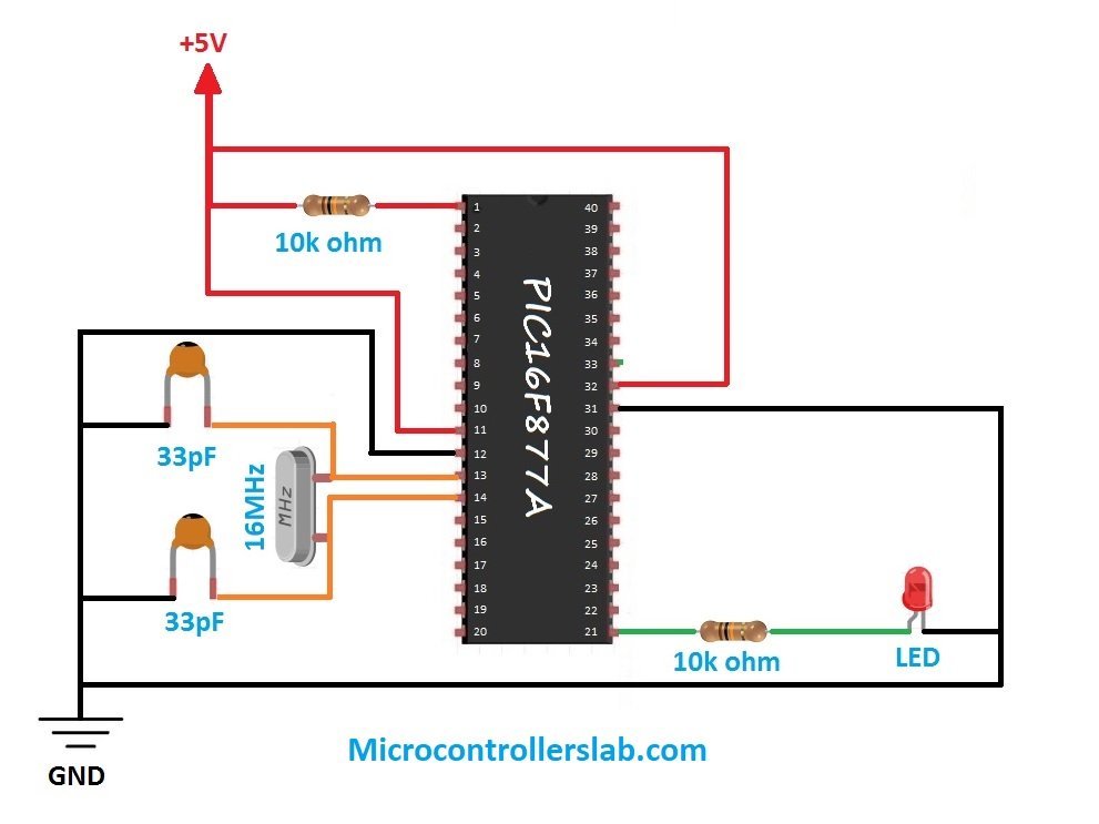
Standard Requirements
Vdd (pwr) and Vss (ground) need to be hooked up with power and ground respectively. Pin 1 is the MCLR pin for the program restart feature. It must be tied to the Vdd with a pull-up resistor in between. Since PIC16F877A does not have an internal oscillator so you need to have an external crystal connected across pin 13 and 14.
PIC Microcontroller General Purpose Input Output Ports
One of the first programs that we recommend with microcontrollers is to used LED blinking example or how to use a push button with a pic microcontroller. To use an LED and a push button with a pic microcontroller, we need to understand general-purpose input/output pins.There are 5 ports in PIC16F877A with ports A and E having fewer pins than ports B, C and D. These are called the digital I/O pins.CCP1 and CCP2, shared with the I/O pins RC1 and RC2, can be used to generate PMW signals with the microcontroller. PGC and PGD pins are used for programming and debugging. This information comes in handy when writing the programming code.
PORTA and TRISA
PortA is a bi-directional port, having 6-bit (A0-A5). The TRISA register is used to determine the status of the corresponding port, i.e. whether it is working as an input port or an output port. If TRISA bit=1, the corresponding port pin is set as input. If TRISA bit=0, the corresponding port pin is set as output. Most of the portA pins are multiplexed with the analog input pins used for A/D converters. Make sure TRISA is set to 1 when using it as an analog input.
PORTB and TRISB
PortB is a bi-directional port, having 8-bit (B0-B7) and TRISB is its data direction register. A bit in PortB is set as input if its corresponding TRISB bit is equal to 1. Whereas if the TRISB bit is cleared, then the corresponding PortB bit will be set as output. RB6 and RB7 are multiplexed with the PGC and PGD functions that are used for programming and debugging.
PORTC and TRISC
Just like PortA and PortB, PortC is an 8-bit, bi-directional port. TRISC bit=1 sets the corresponding PortC bit as input and TRISC bit=0 sets the corresponding PortC bit as output. PORTC is also multiplexed with many peripheral functions.
PORTD and TRISD
PORTD is also an 8-bit, bi-directional port. Each pin in PortD is individually configurable as input or output. It can be configured as a Parallel Slave Port if the 4-bit of TRISE (PSPMODE) is set to 1.
PORTE and TRISE
PORTE has only 3-bits (E0-E2) which are also individually configurable as input or output. All 3 PORTE pins are multiplexed with analog inputs.
Now you know about input-output pins of PIC16F877A. Now we recommend you to read this LED blinking tutorial:PIC Microcontroller Compilers
Two of the most popular compiler that is used to write program for microchip MCUs are MPLAB XC compilers and mikroC Pro for PIC. You can use any compiler. But if you are just getting started, we recommend, mikroC for pic because of its ease of use and built-in libraries. You can read these articles on both compilers:- Pic microcontroller programming in c using Mikroc Pro for PIC
- Getting started & your first Program with MPLABX XC8
Timers and Counters
PIC Microcontrollers have a built-in precise timing system called timers/counters which can be used to perform several tasks such as generating timing signals, calculating the span of an event, keeping a record of date and time and so on. Since the counter runs independently, it can count the instruction cycles simultaneously with the main program execution. PIC16F877A consists of 3 timer modules:
- TIMER0
- TIMER1
- TIMER2
This tutorial gives you the basic knowledge required to get started with PIC Microcontrollers.
Next Steps
The tutorials to follow next include:
- How to program a PIC Microcontrollers
- LED Blinking with PIC Microcontrollers
- LCD Interfacing with PIC Microcontrollers
- Keypad Interfacing with PIC Microcontrollers
- Stepper motor with PIC Microcontrollers
- Servo motor with PIC Microcontrollers
- Serial Communication using PIC Microcontrollers
- Pulse Width Modulation using PIC Microcontrollers
- Seven Segment display counter 0-99 using PIC Microcontrollers
It really seems very useful to the begginners to learn the embedded and the PIC controllers, if it had been a visual learning itwould have been a better opputunity