External INTERRUPT IN PIC18F452: Sometimes External devices are connected with microcontroller. If that external device has to send some information to microcontroller, then microcontroller needs to know about this situation to get that information. An example of such an external device is the digital thermometer. It measures the temperature and at the end of measurements transmits results to the microcontroller. Now the purpose of this article to explain the fact that how does the microcontroller knows to get the required information from an external device.
Recommended Components
The following components are used in this project or are helpful for building it with a PIC microcontroller.
| Component | How it’s used in this project | Buy on Amazon |
|---|---|---|
| PIC18F452 microcontroller | The PIC microcontroller whose external interrupt (INT) pin is used in this tutorial. | Check Price |
| PICkit 5 programmer/debugger | Programs and debugs the PIC microcontroller. | Check Price |
| Tactile push button | Triggers the external interrupt on a change at the INT pin. | Check Price |
| 5mm LED | Toggled inside the interrupt service routine to show it fired. | Check Price |
| Breadboard | Solderless board to build and test the circuit. | Check Price |
| Jumper Wires | Connect the microcontroller to other components. | Check Price |
As an Amazon Associate we earn from qualifying purchases. Prices and availability are accurate as of the date/time indicated and are subject to change.
Types of interrupts
There are two methods of communication between the microcontroller and the external device:
- By using Polling
- By using Interrupts
POLLING
In this method, the external devices are not independent. We fix the time interval in which microcontroller has to contact the external device. The microcontroller accesses that device at the exact time interval and gets the required information. Polling method is just like picking up our phone after every few seconds to see if we have a call.The main drawback of this method is the waste of time of microcontroller. It needs to wait and check whether the new information has arrived not.
INTERRUPTS
Interrupt is the signal which is sent to the microcontroller to mark the event that requires immediate attention.This signal requests the microcontroller to stop to perform the current program temporarily time to execute a special code. It means when external device finishes the task imposed on it, the microcontroller will be notified that it can access and receive the information and use it.Interrupts are just like waiting for the phone to ring.
INTERRUPT SOURCES in microcontrollers
The request to the microcontroller to stop to perform the current program temporarily can come from various sources:
- Through external hardware devices like pressing specific key on the keyboard, which sends Interrupt to the microcontroller to read the information of the pressed key.
- During execution of the program, the microcontroller can also send interrupts to itself to report an error in the code. For example, division by 0 will causes an interrupt.
- In the multi-processor system, the microcontrollers can send interrupts to each other to communicate. For example, to divide the work between them they will send signals between them.
INTERRUPT TYPES in pic microcontrollers
There are 2 types of interrupts for PIC microcontroller that can cause break.
Software Interrupt: It comes from a program that is executed by microcontroller or we can say that it is generated by internal peripherals of the microcontroller and requests the processor to hold the running of program and go to make an interrupt.
Hardware Interrupt:These interrupts are sent by external hardware devices at certain pins of microcontroller.
INTERRUPTS IN PIC18F452
Following interrupts sources are present in PIC18F452
- Timer over interrupt
- Pins RB0, RB1, RB2 for external hardware interrupts (INT0, INT1, INT2)
- PORTB Change interrupts (any one of the upper four Port B pins. RB4-RB7)
- ADC (analog-to-digital converter) Interrupt
- CCP (compare capture pulse-width-modulation) Interrupt
- Serial communication’s USART interrupts (receive and transmit)
- Reset, Brown-Out Reset, Watch-dog Reset, Power On Reset
- Parallel Port Read/Write Interrupt
- Master Synchronous Serial Port Interrupt
- Data EEPROM Write Complete Interrupt
REGISTER CONFIGURATION for external interrupt
These are the registers for interrupt operation and minimum 1 register can be used to control the interrupt operation in PIC18F452 which are:
- RCON (Reset Control Register)
- INTCON, INTCON2, INTCON3 (Interrupt Control Registers)
- PIR1, PIR2 (Peripheral Interrupt Request Registers)
- PIE1, PIE2 (Peripheral Interrupt Enable Registers)
RCON Register:
- Reset control register
- IPEN bit to enable interrupt priority scheme, 1= enable priority level on interrupts
- Other bits used to indicate the cause of reset RI (Reset Instruction flag), TO (Watchdog Time Out flag), PD (Power on Detection flag), POR (Power on Reset status) and BOR (Brown Out Reset status bit)
INTCON Register:
- 3 Interrupt control registers INTCON, INTCON2, INTCON3
- Readable and writable register which contains various enable and flag bits
- Interrupt flag bits get set when an interrupt condition occurs
- Contain enable, priority and flag bits for external interrupt, port B pin change and TMR0 overflow interrupt
PIE Register:
- Peripheral Interrupt Enable register
- May be multiple register (PIE1, PIE2), depending on the number of peripheral interrupt sources
- Contain the individual bits to enable/disable Peripheral interrupts for use
PIR Register:
- Peripheral Interrupt Flag register
- May be multiple register (PIR1, PIR2), depending on the number of peripheral interrupt sources
- Contain bits to identify which interrupt occurs (flags)
- Corresponding bits are set when the interrupt occurred
EXTERNAL INTERRUPT registers setting
INTCON registers are just used to configure the external PIC interrupts. This article also deals with external interrupts of PIC18F452 so we will discuss it in detail here..
FOR PERIPHERAL INTERRUPT:
The PIE (Peripheral Interrupt Enable) and PIR (Peripheral Interrupt Request) registers are used to configure the Peripheral (Internal) Interrupts.
INTCON REGISTER: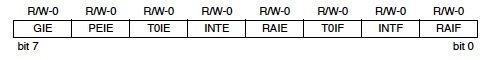
GIE: Global Interrupt Enable
This bit is set high to enable all interrupts of PIC18F452. 1 = Enable all interrupts 0 = Disable all interrupts
PEIE: Peripheral Interrupt EnableThis bit is set high to enable all the peripheral interrupts (Internal interrupts) of the microcontroller. 1 = Enable all peripheral interrupts 0 = Disable all peripheral interrupts
T0IE: TMR0 Overflow Interrupt EnableThis bit is set high to enable the External Interrupt 0. 1 = Enable TMR0 overflow interrupt 0 = Disable TMR0 overflow interrupt
INTE: INT External Interrupt Enable
This bit is set high to enable the external interrupts. 1 = Enables the INT external interrupt 0 = Disables the INT external interrupt
RBIE: RB Interrupt Enable
This bit is set high to enable the RB Port Change interrupt pin. 1 = Enables the RB port change interrupt 0 = Disables the RB port change interrupt
T0IF: TMR0 Overflow Interrupt Flag
1 = TMR0 register has overflowed (it must be cleared in software) 0 = TMR0 register has not overflowedINTF: INT External Interrupt Flag 1 = The INT external interrupt occurred (it must be cleared in software) 0 = The INT external interrupt did not occur
RBIF: RB Port Change Interrupt Flag
1 = At least one of the RB7:RB4 pins changed the state (must be cleared in software) 0 = None of RB7:RB4 pins have changed the stateINTCON2 REGISTER:
RBPU: Port B Pull up Enable
1 = All port B pull ups are disabled 0 = All port B pull ups are enabled by individual port latch values
INTEDG0, INTEDG1, INTEDG2: External Interrupt Edge select
These bits are used to select the triggering edge of the corresponding interrupt signal on which the microcontroller is to respond. 1 = Interrupt on rising edge 0 = Interrupt on falling edge
Bit 3, Bit 1: Unimplemented
It is always read as 0
TMR0IP: TMR0 overflow priority
1 = High priority 0 = Low priorityRBIP: RB Port change Interrupt Priority
1 = High priority 0 = Low priority
INTCON3 REGISTER: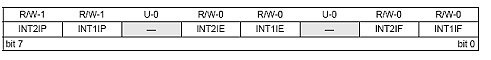
INT1IP, INT2IP:
These bits are used to set priority of the interrupts 1 and 2, respectively. 1 = High priority 0 = Low priority
Bit 5, Bit 2:
Both are unimplemented and read as 0.
INT1IE, INT2IE:
These bits enable/disable the External Interrupt 1 and 2, respectively. 1 = Enables the External Interrupt x 0 = Disables the External Interrupt x
INT1IF, INT2IF:
These are External Interrupt 1 and 2 flag bits, respectively. 1 = The INTx External Interrupt occurred (must be cleared in software) 0 = The INTx External Interrupt did not occur
EXAMPLE OF USING INTERRUPTS IN PIC18F452
Here we will configure the External Interrupt 0 (INT0). PORT D is used as output port and it is monitored through a set of 8 LEDs. Reset is given through pin 1. Push button is connected to RB0 for external interrupt source and 12 MHz crystal is connected to microcontroller.
Programming Steps:
- Firstly we enable the External Interrupt 0 by setting INT0IE bit high (INTCON=0x10).
- Set the interrupt on falling edge by setting the INTEDG0 in INTCON2 to zero (INTCON2=0)
- Set the Global InterruptEnablein INTCONto high (INTCON.GIE=1)
- Start a while loop and initialize PORTD with certain value (LATD=0xAA)
- Then write the ISR (Interrupt Service Routine) for the interrupt [ header as interrupt () ]
- Clear the INT0IF bit of INTCON (INTCON.INT0IF=0)
- Invert or toggle the value at PORTD (LATD=~LATD)
Working:
PORT D LEDs will on as 10101010. When button at RB0 is pushed, interrupt service routine will start. It will invert (or toggle) the output at PORTD. After 1 sec while loop will again start.
Proteus Simulations:
Hardware results
Code:
void main()

{

    TRISD=0;                                          // PortD as output port

    INTCON=0x10;                              // Enable INT0

    INTCON2=0;                                   // Set Falling Edge Trigger for INT0

    INTCON.GIE=1;                             // Enable Global Interrupt

while(1)

    {

        LATD=0xAA;                               //Set some value at PortD

    }

}

void interrupt()                                 // Interrupt Service Routine

{

    INTCON.INT0IF=0;                       // Clear the interrupt 0 flag

    LATD=~LATD;                                 // Invert (Toggle) the LEDs at PortD

Delay_ms(1000);              // Delay for 1 sec

}
So this is all about how to use external interrupt of pic microcontroller. External interrupt has many applications in embedded systems. Real time operating systems also use interrupts. Visitor counter is also an example of external interrupt.
Even after using the same code as above our pic is not getting interrupted in proteus.Our code is:
#include
#pragma config OSC = HS
#pragma config WDT = OFF
#pragma config PWRT = OFF
#pragma config BOREN = ON
#pragma config LVP = OFF
#pragma config CPD = OFF
#define _XTAL_FREQ =12000000
#define mybits PORTBbits.RB7
void INT0_ISR(void);
void INTERRUPT();
void delay();
void main()
{ TRISD=0X00;
TRISBbits.TRISB0=1;
INTCONbits.INT0IF=0;
INTCONbits.INT0IE=1;
INTCONbits.PEIE=0;
INTCONbits.GIE=1;
INTCON2bits.INTEDG0 = 1; // Interrupt on rising edge
while(1)
{ LATD=0X00;
}
}
void INTERRUPT()
{
if(INTCONbits.INT0IF==1)
{
void INT0_ISR();
}
}
void INT0_ISR()
{
int i;
INTCONbits.INT0IF=0;
LATD=0XFF;
for(i=0;i<1000;i++);
LATD=0XFF;
}
What could be the possible problem?Please help!
It is very poor code.
Delay inside interrupt ???
It is just for the demo purpose, for practical use, you can make a separate LED blinking code and call it whenever an interrupt occurs.