Rotary Encoder Module in interfacing with pic16F877A microcontroller, In this tutorial, I will show you how to interface rotary encoder with pic microcontroller. How to use rotator encoder for measurement of shaft rotation and position. What is rotary encoder and how rotary encoder works? How to interface it with PIC16F877A microcontroller? How to count each tick of rotary encoder with pic microcontroller and display it on 16X2 liquid Crystal display. So let’s start with the introduction of rotary encoder.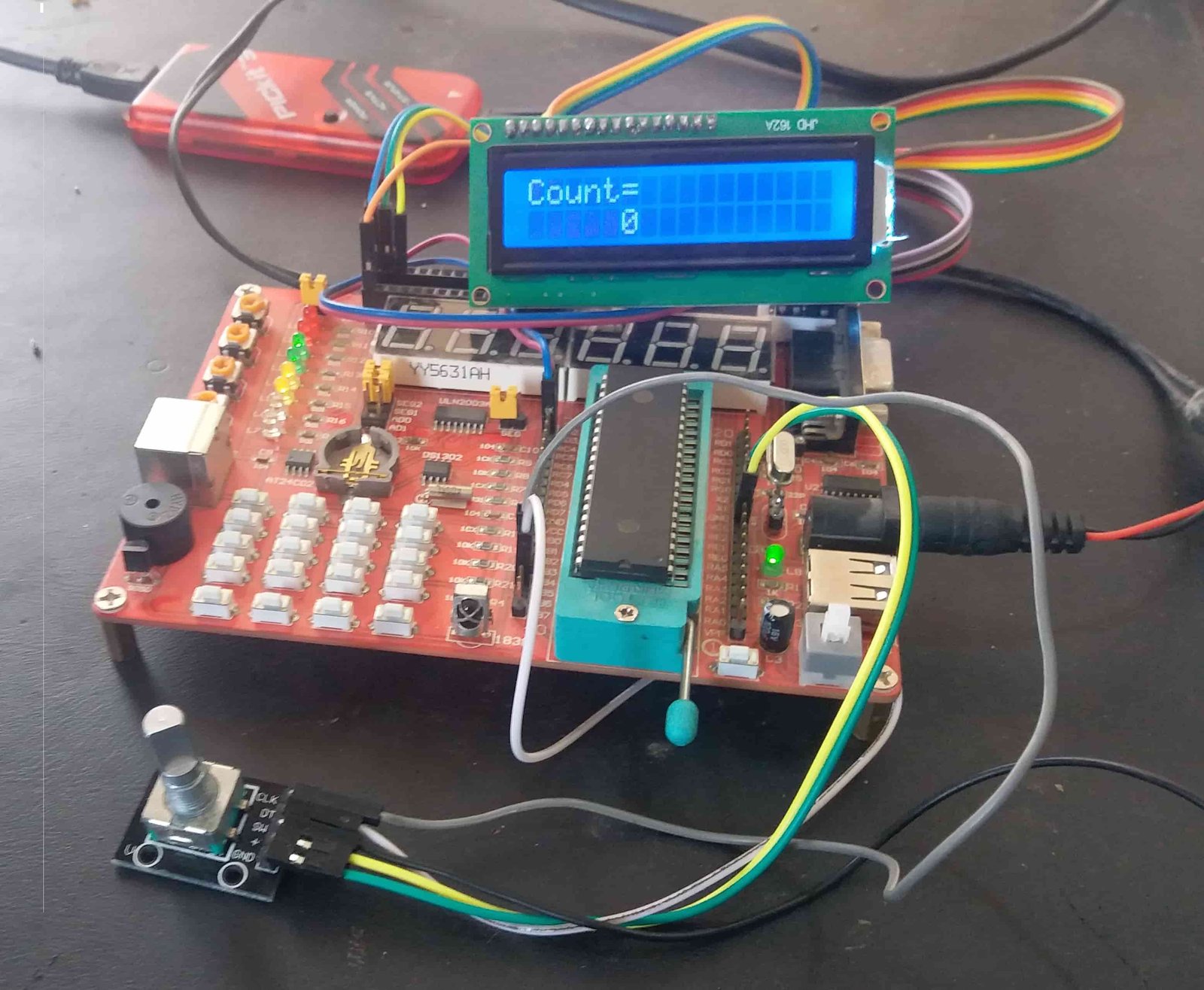
I have already posted a article of rotatory encoder interfacing with Arduino and stepper motor control you may also like to read it:
What is Rotary Encoder Module?
Rotary encoder is a such type of encoder which is used for measuring the angular position of any rotating shaft and then it generates the electrical signal according to shaft the movement. This electrical signal could be in the form of pulses or analog, depends upon the type of encoder. These encoders are also known as shaft encoder and by using these encoders the user can easily defined the angular position, speed, linear displacement and direction of rotation of any shaft or any moving object. A Simple rotary encoder module is shown is figure 1

Figure 1 A Simple Rotary Encoder
Pin Configuration of Rotary Encoder Module
Rotary encoder module consists of five pins such as CLK, DT, SW, + and GND shown in figure 2. According to the figure 2, for check the normal working of rotary encoder GND pin is connected to ground and positive voltages are applied at + pin. These voltages should be with in the rage of 3.3 volts to 5 volts for normal working of this encoder. Similarly, two light emitting diodes (LEDs) are connected at pins CLK and DT with the help of two 220 ohms resistor which are connected in series with these light emitting diodes. Clk and DT pins produce square waves which are 90 degree out of phase with each other and these two square waves are used to measure clock wise and anti clock wise rotation of shaft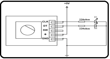
Figure 2 Pins Configuration of Rotary Encoder Module
Types with Working of Rotary Encoder
Normally two types of encoders are currently used in market first one is magnetic encoder and second one is optical encoder. These are further divided into two types first one is absolute and second one incremental encoder. If we talk about magnet encoder, then it consists of a rotating disk and proximity sensor. The rotating disk consists of teethes when these teethes move then proximity sensor senses the movement of these teethes and then produces the pulses according to this movement. This encoder is quite simple as compared to incremental encoder. Similarly, if we talk about optical encoder then it consists of IR LED, photo transistor and rotating disk which consists of transparent segments. When IR LED emits the lights then this light pass through transparent segment of rotating disk then this light is received by photo transistor.
For further understanding we have divided the disk into two segments such as conductive and non conductive segment. Dark segment is the conductive segment and white segments is the nonconductive segment. A and B are two outputs of this rotary encoder shown in figure 3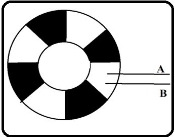
Figure 3 Rotary Encoder Disk Segments
Dark or conductive segment is directly connected with positive + 5 volts, similarly when the disk moves in clock wise direction then dark segment directly coupled with output point A then +5 volts are received at point A. After that, when this segment has passed then white segment directly coupled with point A then zero volts are received at point A. Similarly, square wave pulses are received at output point A. So, the same waves are received at output point B. If the LEDs are connected at these output, then it would be turned on and off after some time. 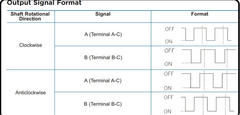
How to Interface Rotary Encoder with PIC16F877A Microcontroller
As we have discussed in above paragraph the rotary encoder is connected according to its pin configuration. Because it consists of two outputs therefore these outputs are connected to any digital input of ports of pic16f877a microcontroller. Microcontroller is programmed in c language with help of mikro/c software and is also powered up with 5 volts dc. When the rotary encoder disk moves in any direction with the rotating shaft of any motor or any object then the voltages are generated in the form of pulses. These pulses are observed by the microcontroller so intelligently and then count these pulses with so efficiently. LCD display could be also interfaced with microcontroller.
If LCD display is interface with microcontroller then this controller easily displayed the direction of rotation and revolution per minute (RPM) of rotating shaft as well as with angle of rotations. Similarly, if this rotary encoder interface with pic microcontroller is used with any conveyor built at which objects are moved then this pic microcontroller interface with rotary encoder module can also tells displacement of the object form its original point.
In this tutorial, we have use PIC16F877A microcontroller, output pins of rotatory encoder module is connected with PORTB pin number 4 and 5. These pins 4 and 5 are configured as input pins. Interrupt is used to detect whenever rotary encoder rotates in a specific direction. LCD is connected with PORT D of pic16F877A microcontroller to display the counts. Video below shows the complete demonstration of this project.
Code
Code is written using MikroC for pic compiler.
sbit LCD_RS at RD2_bit;
sbit LCD_EN at RD3_bit;
sbit LCD_D4 at RD4_bit;
sbit LCD_D5 at RD5_bit;
sbit LCD_D6 at RD6_bit;
sbit LCD_D7 at RD7_bit;

sbit LCD_RS_Direction at TRISD2_bit;
sbit LCD_EN_Direction at TRISD3_bit;
sbit LCD_D4_Direction at TRISD4_bit;
sbit LCD_D5_Direction at TRISD5_bit;
sbit LCD_D6_Direction at TRISD6_bit;
sbit LCD_D7_Direction at TRISD7_bit;
// End LCD module connections
signed int count=0; //this variable will incremented or decremented on encoder rotation
char text[7];

#define REA PORTB.B4 // Rotary encoder pin definition
#define REB PORTB.B5


void pbchange(void )
{
unsigned char state;
static unsigned char oldstate; // this variable need to be static as it has to retain the value between calls
delay_ms(1); // delay for 1ms here for debounce
state= (REB<<1 | REA); // combine the pin status and assign to state variable
if(oldstate==0x0){
if( state ==0x1)
{
count--; //decrement the count
//lcd_out(1,8,count);
}else if( state == 0x2)
{

count++; //decrement the count
//Lcd_Out(1,8,count);
}

}
oldstate = state; // store the current state value to oldstate value this value will be used in next call

PORTB = PORTB; // read or Any read or write of PORTB,This will end the mismatch condition
INTCON.RBIF = 0; // clear the porb change intrrupt flag
}
void interrupt(void)
{

if(INTCON.RBIF==1) //check for PortB change interrupt
{
pbchange(); //call the routine
}

}

void main() {

TRISB.B4=1; // set rotary encoder pins to input
TRISB.B5=1;
// inilized the LCD
Lcd_Init(); // Initialize LCD
Lcd_Cmd(_LCD_CLEAR); // Clear display
Lcd_Cmd(_LCD_CURSOR_OFF); // Cursor off
Delay_ms(100); // Wait for UART module to stabilize


Lcd_Out(1,1,"Count=");
// display count to lcd
OPTION_REG.B7 =0; // enable pullups
INTCON.RBIF = 0; // clear the interrupt flag
INTCON.RBIE = 1; // enable PORTB change interrupt
INTCON.GIE = 1; // enable the global interrupt
while(1)
{
//UART1_Write_Text(text);
IntToStr(count, text);
Lcd_Out(2,1,text);

}

}
Sir can you give me asource code
there is no change in count why? display is ok it is showing 0
can you share schematics
Why we are taken the digital i/o ports why can’t we go to other pins?