In this tutorial, we will learn about the KY-026 infrared flame sensor module and how to interface it with a PIC microcontroller. We will also see how to use it for fire detection. By the end of this article, you will be able to learn about the introduction of the flame sensor, its working principle, features, and pinout. Additionally, we will write a PIC microcontroller code to detect fire and control a buzzer in case of fire detection.

In this tutorial, we will use the PIC16F877A microcontroller, which is an 8-bit microcontroller and belongs to the mid-range family of PIC microcontrollers. Also, we will use MikroC for PIC compiler to write the code, and PicKit 3 is used to upload the code to the PIC microcontroller.
Recommended Components
The following components are used in this project or are helpful for building it with a PIC microcontroller.
| Component | How it’s used in this project | Buy on Amazon |
|---|---|---|
| PIC16F877A microcontroller | Reads the flame sensor D0 output on a digital input pin and drives the buzzer output. | Check Price |
| PICkit 5 programmer/debugger | Uploads the compiled hex file into the PIC16F877A and debugs the circuit. | Check Price |
| Flame sensor module | Detects infrared light from a flame and sends a logic-high signal to the PIC when fire is present. | Check Price |
| Breadboard | Holds the PIC and flame sensor module for solderless prototyping. | Check Price |
| Jumper Wires | Connect the flame sensor D0, VCC and GND pins to the PIC and power rails. | Check Price |
As an Amazon Associate we earn from qualifying purchases. Prices and availability are accurate as of the date/time indicated and are subject to change.
Infrared Flame or Fire Sensor Introduction
The flame sensor is used to detect fire or other light sources within the range of wavelengths from 760nm to 1100nm. The module consists of an IR sensor, a potentiometer, OP-Amp circuitry, and an LED indicator. When a flame is detected, the module will turn on its red LED. This module is sensitive to flames, but it can also detect ordinary light. The detection point is set at 60 degrees. The sensitivity of this sensor is adjustable and it also has stable performance.
It has both outputs, analog and digital. The analog output gives us a real-time voltage output signal on thermal resistance while the digital output allows us to set a threshold via a potentiometer. In our tutorial, we are going to use both of these outputs one by one and see how the sensor works.
We can use the flame sensor to make an alarm when detecting a fire, for safety purposes in many projects and in many more ways.
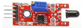
There are many types of flame sensors available in the market but we will use IR infrared flame sensor module in this tutorial. A picture of this flame sensor is shown below. As you can see in the picture, the main component of this sensor is an IR receiver that is a photodiode. This photodiode is used to detect flame and fire.
Fire Detection with Flame Sensor
Whenever a flame emits or a fire burns in the surroundings, it emits small amounts of infrared light. This infrared light is used to detect the flame or fire by this IR-based flame sensor. The IR receiver of the flame sensor collects these IR waves, which are emitted due to the burning fire. This IR receiver is connected to an operational amplifier, which provides the output in the form of voltage at the sensor’s output. We will simply connect this output to a Pic microcontroller and process this information to turn on an LED, which we will connect to the board as an output. So, whenever a fire or flame is detected around the flame sensor, the digital output pin (DO) goes high. When no fire is detected, the output pin DO will give a logic low or zero volts.
Flame sensor IR receiver collects the IR waves emitted due to fire burning. This IR receiver is connected to an operational amplifier which provides the output in the form of voltage. We will simply connect this output to the pic16f877a microcontroller and process this information to turn on an alarm or buzzer, which will be connected as an output. So, whenever fire or flame is detected by the flame sensor, the output pin goes high, and you will notice 5 volts at pin D0 of the sensor. When no fire is detected, the output pin will give logic low or zero volts.
Features
The flame sensor module has the following features:
- The operating voltage is from 3.3 – 5V.
- It gives us both analog and digital output.
- It has an LED indicator, which indicates whether the flame is detected or not.
- The threshold value can be changed by rotating the top of a potentiometer.
- Flame detection distance, lighter flame test can be triggered within 0.8m. If the intensity of flame is high, the detection distance will be increased.
- The detection angle of the flame sensor module is about 60 degrees.
Flame Sensor Pinout
As shown in the diagram below. It has four pins. The functionality of each pin is given below:

Vcc pin: It is a power supply pin. The operating voltage of this sensor is 3.3 volts to 5 volts. But I recommend you connect 5 volts to this pin to avoid any compatibility issues with the microcontroller.
Ground pin: You should connect this pin to the ground terminal of the power supply. Remember, the ground of the PIC16F877A microcontroller and the flame sensor should be the same if you are using a different power supply for the flame sensor and the microcontroller.
A0 pin: It is an analog voltage output pin. The voltage across this pin varies according to the intensity of the fire or flame. But if you are designing only a fire detector circuit using this flame sensor, I recommend you use the other output pin (D0).
D0 pin: This is a digital output pin. I have already discussed it earlier.
Interfacing Flame Sensor with Pic Microcontroller
Let’s see how we can interface a flame sensor with a PIC microcontroller. As we mentioned earlier, we are using the PIC16F877A microcontroller in this tutorial.
To connect it with the PIC microcontroller, we need to select any digital input/output pin of the PIC16F877A. In the diagram shown below, we have connected IO pin D0 with RD0 pin of the PIC16F877A. RD0 is pin number 0 of PORTD of the PIC16F877A. In programming, we will declare this pin as an input, as we want to detect the logic high and low of the flame sensor. The rest of the connections are self-explanatory. We have connected a buzzer to PORTC pin number 0. The buzzer will be used as an output. Whenever the flame sensor detects a fire, the microcontroller will turn on this buzzer or alarm.

Code
The code for this project is written in the MIKROC compiler. If you do not know how to use MikroC for Pic, you can refer to these tutorials:
- How to Use “MikroC PRO for PIC” to Program PIC Microcontrollers
- Pic microcontroller programming in c using Mikroc Pro for PIC
To write code for this project, we need to use one pin of PIC16F877A as a digital input pin and one pin as a digital output pin. Because the PIC16F877A microcontroller captures the output of the flame sensor as an input, and based on this input, the microcontroller makes a decision to turn on or turn off the buzzer, which is used as an output device.
void main(void)
{
    // Initialize the input pin on PORTD.B0 as low
    PORTD.B0 = 0;

    // Configure PIN NUMBER 1 (PORTD.B0) as an input
    TRISD.B0 = 1; // PIN NUMBER 1 IS DECLARED AS AN INPUT

    // Initialize the output pin on PORTE.B0 as low
    PORTE.B0 = 0;

    // Configure PIN NUMBER 1 (PORTE.B0) as an output
    TRISE.B0 = 0; // PIN NUMBER 1 IS DECLARED AS AN OUTPUT

    while(1) { // Start of an endless loop
        // Check if input pin (PORTD.B0) is in high state (logic level 1)
        if (PORTD.B0 == 1) {
            // If fire is detected, turn on the buzzer by setting the output pin (PORTE.B0) to high
            PORTE.B0 = 1; // It will make the buzzer on
        } else {
            // If no fire is detected, turn off the buzzer by setting the output pin (PORTE.B0) to low
            PORTE.B0 = 0; // It will make the buzzer off
        }
    } // End of the endless loop
}
How Does Code Work?
This code is used for fire detection and controlling a buzzer as an alert system.
Pin Configuration
This sets the pin connected to PORTD (Digital Port D) and bit 0 to a low state (logic 0).
PORTD.B0=0This configures pin 0 of PORTD as an input, which typically implies that it’s connected to a sensor or switch.
PORTD.B0=1Buzzer Control Setup
This initializes the pin connected to PORTE (Digital Port E) and bit 0 to a low state (logic 0).
PORTE.B0=0This configures pin 0 of PORTE as an output, suggesting that it’s connected to a buzzer.
TRISE.B0=0The code then enters an infinite loop that continuously monitors the state of the input pin connected to PORTD.B0, which is intended to detect a fire condition.
if( PORTD.B0==1): This checks if the input pin is in a high state (logic level 1), indicating that the fire sensor has detected a fire.
PORTE.B0=1: If a fire is detected (input pin is high), this turns on the buzzer by setting the output pin on PORTE.B0 to a high state (logic 1). This activates the buzzer as an alert. else: If the input pin is not high (fire is not detected):
PORTE.B0=0: This turns off the buzzer by setting the output pin on PORTE.B0 to a low state (logic 0).
The overall behavior of this code is to monitor the input pin connected to a fire sensor. When the sensor detects a fire and sets the input pin high, the code responds by turning on the connected buzzer via the output pin. If no fire is detected (input pin low), the buzzer remains off. This arrangement creates a simple fire detection system where the buzzer serves as an alert mechanism.
Demonstration
Conclusion
In conclusion, this guide has provided a comprehensive overview of the KY-026 flame sensor and its interface with the PIC microcontroller for fire detection. We have explored the working principle of the flame sensor, its features, and pinout. Additionally, we have discussed the process of interfacing the flame sensor with the PIC microcontroller and programming it for fire detection. By following the steps outlined in this tutorial, readers will be equipped with the knowledge and skills necessary to implement fire detection systems using the KY-026 flame sensor and the PIC microcontroller. With its adjustable sensitivity and reliable performance, this flame sensor module offers a valuable solution for detecting flames and ensuring safety in various projects.
Related content:
- MPU6050 Sensor Module Interfacing with Pic Microcontroller
- DHT22 Temperature and Humidity Sensor Interfacing with Pic Microcontroller
- LM35 Temperature Sensor with 7-Segment Display using Pic Microcontroller
- Infrared Obstacles Avoidance Sensor Module interfacing with pic microcontroller
- MQ-2 gas sensor interfacing with pic microcontroller
- Rain Drop Sensor Module Interfacing with Pic Microcontroller– Rain Detector Circuit
- Soil Moisture Sensor YL-69 or HL-69 interfacing with pic microcontroller
what is the specific name of the flame sensor to find out in proteus?
what is the specification for all type sensors used in proteus?
this is helpful