Rain detector circuit using pic microcontroller , In this tutorial, you will learn how to interface rain drop sensor or rain detector circuit with pic16F877A microcontroller. Rain drop is used to detect the presence of rain in sensitive areas where presence of water can damage the food or other things. So this raindrop sensor can be used to detect the rain in such areas. For example you are sleeping inside your home and you have place your important stuff in open part of your home and you sleep with the assumption that there is no chance of rain tonight. But you know nature does not work according to our assumptions. So if its rains that night, if you do know come to know about it at exact time, your important stuff may get damaged. But if you have installed some kind of rain alarm in outside your room, you can avoid this damage as early as possible. So in this pic microcontroller based project, we are designing a drain detector circuit using pic microcontroller and very famous raindrop sensor.
It is a very inexpensive circuit and can be easily place in any open part of your home. you can even interface this rain detector circuit with your mobile phone through Bluetooth by interfacing it with microcontroller and can receive notification of rain on your mobile phone through Android app. you can also interface this circuit with GSM Module and whenever rain drop sensor will detect rain, user will receive message or call on his/here cell phone. So now lets start with introduction of rain detector circuit.
Recommended Components
The following components are used in this project or are helpful for building it with a PIC microcontroller.
| Component | How it’s used in this project | Buy on Amazon |
|---|---|---|
| PIC16F877A microcontroller | Reads the rain sensor analog output on an ADC channel and displays the rain status on the LCD. | Check Price |
| PICkit 5 programmer/debugger | Uploads the compiled hex file into the PIC16F877A and debugs the circuit. | Check Price |
| Raindrop sensor module | Its sensing pad changes resistance when wet, giving the PIC an analog rain-intensity voltage. | Check Price |
| Breadboard | Holds the PIC and rain sensor control board for solderless prototyping. | Check Price |
| Jumper Wires | Connect the rain sensor A0, VCC and GND pins to the PIC and power rails. | Check Price |
As an Amazon Associate we earn from qualifying purchases. Prices and availability are accurate as of the date/time indicated and are subject to change.
Rain Drop Sensor Module Introduction
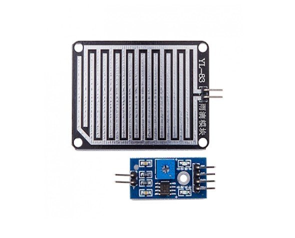
The rain drop sensor module is a smart and low-cost rain sensing device. It has two parts i.e. a rain sensing pad and a control board. The sensitive sensing pad detects any water present on it while the control board reads these signals and can also binarize them. The rain drop module has a major application in the automobile industry. It can be used to monitor the rain and send closure requests to shutters or windows whenever the rain is detected. The post is a guide to help make your own smart project.
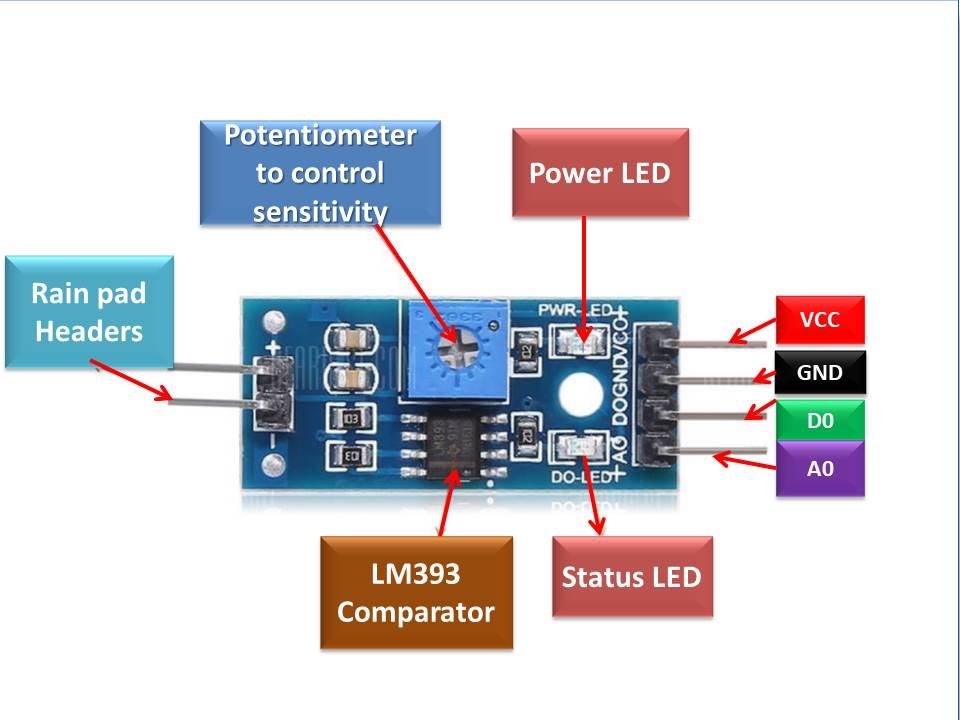
Rain Drop Pinout
The rain drop control sensor is embedded with LM393 voltage comparator, current limiting resistors to adjust signal states and divide the voltage and capacitors as biasing elements. The pinout of the Rain Drop Sensor module is as shown:
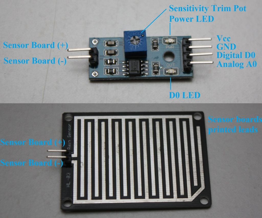
Pin Configuration
The rain drop sensor control board is available at 3.2cm x 1.4cm. The pin configuration in tabular are detailed below:
| Pin Name | Function |
|---|---|
| VCC | Positive power supply pin. It powers the sensor. |
| GND | Reference potential pin |
| D0 | Digital output pin. It gives the digital output of the internal comparator circuit. |
| A0 | Analog output pin. It serves to give analog signals between 0-5 Volts . |
| +/- | Rain pad Connecting Headers |
It consists of two parts one is a blackboard with nickel layers on it and the other is an integrated chip provided with some output pins. Board has 2 output pin and the chip has 6 pins.
Board Pins are
- +
- –
Rain detector circuit is designed using this simple rain sensor module. As I mentioned at the start of article rain sensor module is used to detect rain and it can also be used to detect intensity of rain. Picture of rain drop module is shown below. It consists of two parts. One is electronic part which is used to adjust the sensitivity of this module and also provide output in the form of analog voltage. I will explain later how the output of this sensor works with respect to rain intensity. Other part of rain sensor module is raining board as shown in picture below. When rain falls on raining board, value of output voltage changes at the output of sensor.
Rain Drop Sensor Working
A rain drop sensor is basically a board on which nickel is coated in the form of lines. It works on the principle of resistance. When there is no rain drop on board. Resistance is high so we get high voltage according to V=IR. When rain drop present it reduces the resistance because water is a conductor of electricity and the presence of water connects nickel lines in parallel so reduced resistance and the reduced voltage drop across it.
Copper Pads
The working of the rain sensor module is easy and straightforward. The sensor has a series of exposed copper paths that acts as a variable resistor whose resistance varies according to the amount of water on its surface. Usually, they are not connected but are bridged through the water. This resistance is inversely proportional to the amount of water. The more water on the surface of the rain pads the better is the conductivity and will result in a lower resistance. The sensor produces an output voltage through which it determines whether it is raining or not.
Sensor Module
The rain drop sensor module consists of a control sensor and a rain-sensing pad which can be connected to any microcontroller. The module produces an output voltage according to the resistance of the sensing pad and is given at the analog output pin. The same signal is also passed over to the LM393 high-precision comparator to digitize and is made available at the TTL digital output pin.
Control Circuit
In addition, the rain drop module has a potentiometer that is responsible for adjusting the output of the digital pin. To receive accurate readings, this potentiometer should be calibrated. The potentiometer is connected to the inverting end of the LM393 comparator and sets the reference or threshold voltage while the input analog voltage is applied to the non-inverting side of the comparator. The respective comparator compares both the voltages. This sets two conditions and gives the output accordingly. If the voltage given as an input exceeds the reference voltage then the comparator shows a high state.
Indication LED
Whereas if the threshold voltage is greater than the applied voltage then the comparator output will be low. Apart from these, the module has a power LED and a status LED. The power LED will light up when the module is powered while the status LED glows and indicates the digital output pin status.
Rain detector circuit with pic microcontroller
So now lets see how to interface this rain drop sensor with pic microcontroller. To interface this rain drop sensor with pic microcontroller , you need to use analog to digital converter module of pic microcontroller. Because we want to measure analog voltage of rain sensor which will appear at the analog pin of rain detection circuit. So you should know, how to measure analog voltage with pic microcontroller. IF you don’t know I recommend you to check my article on voltage measurement using pic microcontroller and we will be display status of rain on LCD, so you should also know how to interface LCD with pic16f877a microcontroller
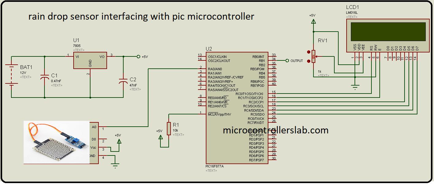
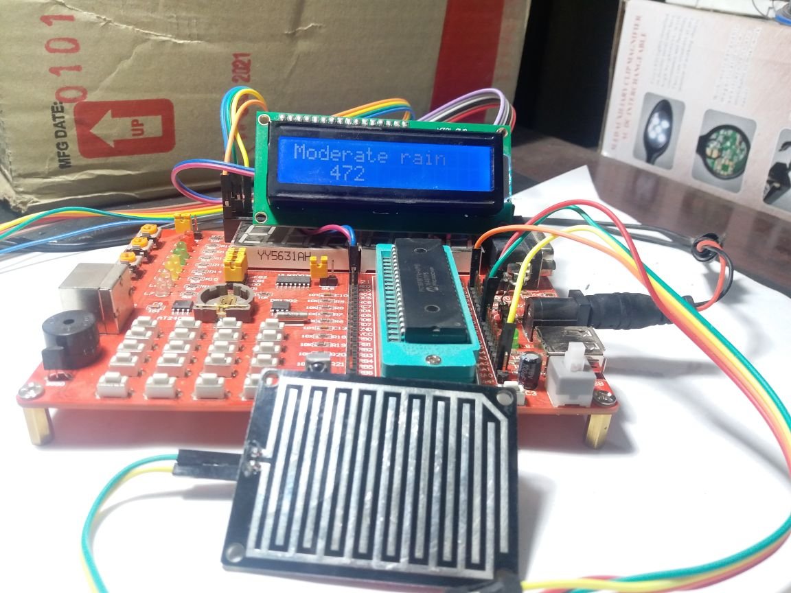
Circuit diagram of rain detection circuit or sensor interfacing with pic microcontroller is shown below.
LCD is connected with PORTC of pic16F877A microcontroller which will display the status of rain. If no rain , LCD will display no rain and it will also display the status of moderate rain and heavy rain according to intensity of rain. Output of rain drop sensor is connected with analog pin zero of PIC16F877A microcontroller.
Code of rain detector circuit using pic microcontroller
Code for rain detection circuit with pic microcontroller is written using Mikro C for pic compiler. There are many types of pic microcontroller compilers available but it is my best choice because of many reasons. You simply copy this code and upload it pic16f877a microcontroller using pic kit3 programmer. and make a circuit diagram according to above connections.
// LCD module connections
sbit LCD_RS at RC0_bit;
sbit LCD_EN at RC1_bit;
sbit LCD_D4 at RC2_bit;
sbit LCD_D5 at RC3_bit;
sbit LCD_D6 at RC4_bit;
sbit LCD_D7 at RC5_bit;

sbit LCD_RS_Direction at TRISC0_bit;
sbit LCD_EN_Direction at TRISC1_bit;
sbit LCD_D4_Direction at TRISC2_bit;
sbit LCD_D5_Direction at TRISC3_bit;
sbit LCD_D6_Direction at TRISC4_bit;
sbit LCD_D7_Direction at TRISD5_bit;

////// rain detection circuit sensor variable///////

float rain_value;
char text[10];
void main(void)
{

ADC_Init(); // it will initialize the adc module of pic16f877a microcontroller
Lcd_Init(); // Initialize LCD
Lcd_Cmd(_LCD_CLEAR); // Clear display
Lcd_Cmd(_LCD_CURSOR_OFF); // Cursor off
Lcd_Out(1,1,"Rain sensor" ); // Write text in first
delay_ms(2000);
Lcd_Cmd(_LCD_CLEAR); // Clear display

while(1)
{ // Endless loop

moisture_value = ADC_Read(0); // It will read the moisture value of sensor
if( moisture_value < 300 )
Lcd_Out(1,1, "Heavy rain" );
else if( moisture_value < 500 )
Lcd_Out(1,1, "Moderate rain" );
else
Lcd_Out(1,1, "No rain" );
//***** it will display the rain intensity in percentage format/////////
moisture_value = ( moisture_value * 100) / (1023); // it converts the moisture value on percentage
FloatToStr(moisture_value, Ltrim(text));
Lcd_Out(2,1, text );
Lcd_Out_cp("%");

}
}
So this is all about how to design rain detection circuit using pic microcontroller. you may also like to check followings:
i do appreciate it and ilike to to see more tutorials it is impressive
what is the name of the sensor used in Proteus , i dont know bc u block it with picture of rain sensor
sir,
I want to see the output (whether its raining or not) in the system. How to do?
I don’t want to use an LCD display.
What is the name of sensor used please denote me the name of rain drop sensor used
Hi, did you find out the name of the sensor used?
Have you got name of sensor used?