In this tutorial, we will learn to interface DHT22 temperature and humidity sensor with pic microcontroller. We will begin with an introduction of DHT22, its pinout diagram, Features, internal circuit. After that we will discuss interfacing circuit diagram. At the end of tutorial, we see programming examples in MPLAB compiler and MikroC Pro for pic.
Recommended Components
The following components are used in this project or are helpful for building it with a PIC microcontroller.
| Component | How it’s used in this project | Buy on Amazon |
|---|---|---|
| PIC16F877A microcontroller | Host MCU that reads temperature and humidity from the DHT22. | Check Price |
| PICkit 5 programmer/debugger | Flashes the compiled firmware onto the PIC and debugs it. | Check Price |
| DHT22 sensor | Digital temperature and humidity sensor read on a single data line. | Check Price |
| Breadboard | Solderless base for wiring the PIC to the DHT22 sensor. | Check Price |
| Jumper Wires | Connect the data and power lines between parts. | Check Price |
As an Amazon Associate we earn from qualifying purchases. Prices and availability are accurate as of the date/time indicated and are subject to change.
DHT22 Introduction
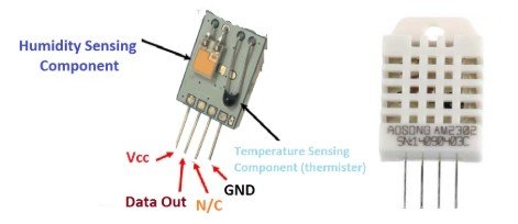
The DHT-22 is a sensor which measures relative humidity and temperature sensor and provides a calibrated digital output. It is an inexpensive sensor that is almost similar to the DHT11 but measures temperature and humidity with higher accuracy and wider range. You don’t need extra components for operation. It is pre-calibrated, and you can directly connect it to obtain the output. The DHT22 sensor is composed of a humidity sensing sensor and a thermistor. These two components measure the humidity and temperature and send out a digital signal on the data pin.
Pin Configuration Diagram
This figure shows the pinout diagram of DHT22 humidity and temperature sensor. It consists of three pins.
Pin Description
The DHT22 sensor is very simple and easy to use. It has only four pins.
- Vcc is the power pin. Apply voltage in a range of 3.5 V to 5.0 V at this pin.
- Data Out is the digital output pin. It sends out the value of measured temperature and humidity in the form of serial data.
- N/C is a not connect pin.
- GND: Connect the GND pin to main ground.
Features
The important features of DHT22 sensor are:
- The range of operating voltage (
) is 3 V to 5 V power.
- It measures temperature in a range of -40°C to +125°C with an accuracy of ± 0.5 degrees.
- The measuring range for humidity is from 0 to 100% with an accuracy of 2-5%.
- The maximum operating current for DHT22 sensor is 2.5mA.
- The sampling rate for DHT22 sensor is 0.5 Hz. It takes measurement once every 2 seconds.
- The sensor has four pins with 0.1″ spacing and a size of body is 15.1mm x 25mm x 7.7mm.
Where to use it?
It is small in size and utilizes low power. It has a long transmission distance of about 20m. Normally, we use DHT22 sensor in applications for measuring ambient temperature and humidity. You can also use DHT11 sensor as it has same function but DHT22 sensor is more reliable as compared to DHT11 sensor. It is pre-calibrated and it has internal temperature compensation.
These sensors are well suited for use in all kinds of harsh applications and you can interface this device with microcontrollers easily. If you need a sensor for measuring temperature in a range of -40°C to +125°C or you need to measure humidity, then this sensor would be ideal for use in such an application.
Connection Diagram with any Microcontroller
The connections are simple as it does not require any external electrical components. It has only four pins in which one is a not connect pin. You can directly connect the other three pins with any microcontroller. The DHT22 sensor does not have any clock pin that means it operates in serial asynchronous mode. It needs a pull-up resistor between and data line to keep it in High logic. This pull-up resistor is essential for communication between the sensor and a microcontroller. Figure (3) shows the basic connection diagram for connecting this sensor.

Interfacing with Pic Microcontroller
The breakout board of this sensor has an onboard pull-up resistor hence you can directly connect its breakout board with PIC microcontroller or Arduino.
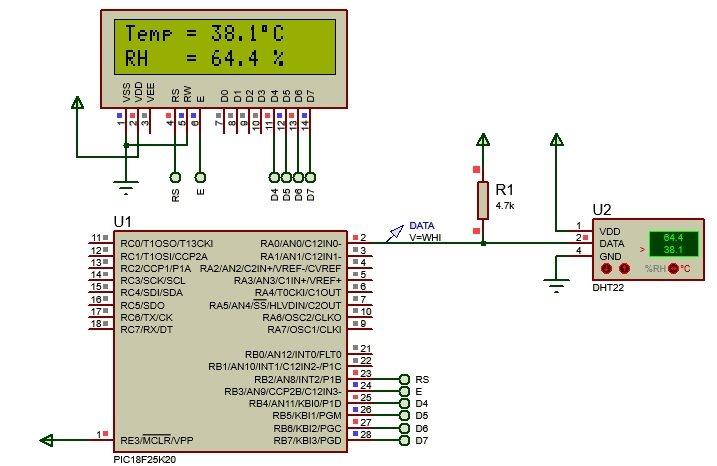
In this example, we have used PIC18F25K20 microcontroller and used the RA0 pin to receive data from DHT22. We use a pull-up resistor of value 4.7 kΩ or 10 kΩ. Connect the data output pin to the RA0 pin of PIC18F25K20. The figure below shows the connections of a DHT22 sensor with Pic microcontroller.

Apply 5V power to the sensor. In some applications, we connect a 100nF capacitor between ground and power in which provides wave filtering. After applying power, don’t send any instructions withing 1 second because the sensor takes one second to give stable output values of temperature and humidity.
We have used 16×2 LCD with PORTB of PIC18F25K20 microcontroller. If you didn’t work with LCD before, you can read this post:
16X2 LCD Interfacing with Pic Microcontroller
MPLAB XC8 Code
This code is for MPLAB XC8 Compiler. If you don’t know how to use MPLAB and XC8 compiler, you can read this complete in-depth guide:
#include <xc.h>
#include <stdio.h>
#define _XTAL_FREQ   4E6

#pragma config IESO = OFF, FOSC = INTIO67, FCMEN = OFF
#pragma config BOREN = OFF, PWRT = OFF
#pragma config WDTEN = OFF
#pragma config CCP2MX = PORTC, PBADEN = OFF, MCLRE = ON
#pragma config DEBUG = OFF, STVREN = ON, XINST = OFF, LVP = OFF
#define LCD_EN       PORTBbits.RB3
#define LCD_RS       PORTBbits.RB2
#define LCD_DATA     PORTB
#define LCD_STROBE() (LCD_EN=1), (LCD_EN=0)


// write a byte to the LCD in 4 bit mode
void lcd_write(unsigned char c)
 { __delay_us(40);
   LCD_DATA &= 0x0f;
   LCD_DATA |= (c & 0xf0);
   LCD_STROBE();
   LCD_DATA &= 0x0f;
   LCD_DATA |= ((c<<4) & 0xf0);
   LCD_STROBE();
 }

// Clear and home the LCD
void lcd_clear(void)
 { LCD_RS = 0;
   lcd_write(0x1);
   __delay_ms(2);
 }

// write a string of chars to the LCD
void lcd_puts(const char * s)
 { LCD_RS = 1;     // write characters
   while(*s)
      lcd_write(*s++);
 }

// write one character to the LCD
void lcd_putch(char c)
 { LCD_RS = 1;     // write characters
   lcd_write( c );
 }

// Go to the specified position
void lcd_goto(unsigned char pos)
 { LCD_RS = 0;
   lcd_write(0x80+pos);
 }

// initialise the LCD - put into 4 bit mode
void lcd_init(void)
 { char init_value;

   init_value = 0x3;
   LCD_RS = 0;
   LCD_EN = 0;

   __delay_ms(15);     // wait 15mSec after power applied,
   LCD_DATA &= 0x0f;
   LCD_DATA |= (init_value<<4) & 0xf0 ;
   LCD_STROBE();
   __delay_ms(5);
   LCD_STROBE();
   __delay_us(200);
   LCD_STROBE();
   __delay_us(200);
   LCD_DATA &= 0x0f;
   LCD_DATA |= (2<<4) & 0xf0;   // Four bit mode
   LCD_STROBE();

   lcd_write(0x28);  // Set interface length
   lcd_write(0xc);   // Display On, Cursor Off, Cursor Blink off
   lcd_clear();      // Clear screen
   lcd_write(0x6);   // Set entry Mode
 }

#define Data      PORTAbits.RA0
#define DataDir   TRISAbits.TRISA0

char message1[] = "Temp = 00.0 C";
char message2[] = "RH   = 00.0 %";
unsigned short TOUT = 0, CheckSum, i;
unsigned short T_Byte1, T_Byte2, RH_Byte1, RH_Byte2;

// Function Prototypes
void lcd_out (char row, char col, const char * s1);
void delay_1s(void);

void start_signal()
 { DataDir = 0;     // Data port is output
   Data    = 0;
   __delay_ms(18);
   DataDir = 1;     // Data port is input
   __delay_us(30);
 }

unsigned short check_response()
 { TOUT = 0;
   TMR2 = 0;
   TMR2ON = 1;                // start timer
   while (!Data && !TOUT);
   if (TOUT)
      return 0;
   else
    { TMR2 = 0;
      while (Data && !TOUT);
      if (TOUT)
         return 0;
      else
       { TMR2ON = 0;
         return 1;
       }
    }
 }

unsigned short read_byte()
 { unsigned short num = 0;
   DataDir = 1;
   for (i=0; i<8; i++)
    { while (!Data);
      TMR2 = 0;
      TMR2ON = 1;
      while (Data);
      TMR2ON = 0;
      if (TMR2 > 40)
         num |= 1<<(7-i);  // If time > 40us, Data is 1
    }
   return num;
 }

void interrupt tc_int(void)
 { if (TMR2IF)
    { TOUT = 1;
      TMR2ON = 0; // stop timer
      TMR2IF = 0; // Clear TMR0 interrupt flag
    }
 }


void main(void)
 { unsigned short check, sign;
   unsigned int rh, temp;

   // Internal oscillator frequency to 4MHz.
   OSCCON = 0b01010000;

   TRISB = 3;
   PORTB = 0;
   TRISA = -1;

   // RA0 Digital input buffer is enabled.
   // NOTE: PORTB digital input buffers are enabled by CONFIG default (PBADEN=OFF)
   ANSELbits.ANS0 = 0;

   GIE = 1;          // Enable global interrupt
   PEIE = 1;         // Enable peripheral interrupt
   TMR2IE = 1;       // Enable Timer2 interrupt
   T2CON = 0;        // Prescaler 1:1, and Timer2 is off initially
   TMR2IF = 0;       // Clear TMR INT Flag bit
   TMR2 = 0;

   lcd_init();
   lcd_clear();

   // Main loop
   while (1)
    { delay_1s();
      start_signal();
      check = check_response();
      if (!check)
       { lcd_clear();
         lcd_out(1, 1, "No response");
         lcd_out(2, 1, "from the sensor");
       }
      else
       { RH_Byte1 = read_byte();
         RH_Byte2 = read_byte();
         T_Byte1  = read_byte();
         T_Byte2  = read_byte();
         CheckSum = read_byte();

         // From RHT03 (DHT22 equivalent) datasheet:
         // Example: MCU has received 40 bits data from RHT03 as
         // 0000 0010 1000 1100   0000 0001 0101 1111   1110 1110
         // 16 bits RH data       16 bits T data        check sum
         // Check sum=0000 0010+1000 1100+0000 0001+0101 1111=1110 1110
         // RH= (0000 0010 1000 1100)/10=65.2%RH
         // T=(0000 0001 0101 1111)/10=35.1 DEG
         // When highest bit of temperature is 1, it means the temperature is below 0 degree Celsius.
         // Example: 1000 0000 0110 0101, T= minus 10.1 DEG
         //             16 bits T data
         rh   = RH_Byte2 | (RH_Byte1<<8);
         temp = T_Byte2  | (T_Byte1<<8);
         sign = 0;
         if (temp>0x8000)
          { temp &= 0x0fff;
            sign = 1;
           }

         unsigned char rh_buf[5], temp_buf[5];
         sprintf (rh_buf,   "%03u", rh);
         sprintf (temp_buf, "%03u", temp);

         // Check for error in Data reception
         if (CheckSum == ((RH_Byte1 + RH_Byte2 + T_Byte1 + T_Byte2) & 0xFF))
          { message2[7]  = rh_buf[0];
            message2[8]  = rh_buf[1];
            message2[10] = rh_buf[2];

            if (sign)
               message1[6] = '-';
            else
               message1[6] = ' ';
            message1[7]  = temp_buf[0];
            message1[8]  = temp_buf[1];
            message1[10] = temp_buf[2];
            message1[11] = 223;     // Degree symbol
            lcd_clear();
            lcd_out(1, 1, message1);
            lcd_out(2, 1, message2);
          }
         else
          { lcd_clear();
            lcd_out(1, 1, "Checksum Error!");
            lcd_out(2, 1, "Trying Again ...");
          }
       }
    }
 }

void lcd_out (char row, char col, const char * s1)
 { if (row==1)
      lcd_goto(0x00+col-1);
   else
      lcd_goto(0x40+col-1);

   lcd_puts(s1);
 }

void delay_1s (void)
 { for (short i=0; i<10; i++)
      __delay_ms(100);
 }
Proteus Simulation Result
MikroC Code
This code is written using MikroC for Pic compiler. Create a new project with MikroC compiler by selecting PIC16F877A microcontroller and set frequency to 8MHz. If you don’t know how create new project in mikroC, we suggest you read this post:
sbit LCD_RS at RB2_bit;
sbit LCD_EN at RB3_bit;
sbit LCD_D4 at RB4_bit;
sbit LCD_D5 at RB5_bit;
sbit LCD_D6 at RB6_bit;
sbit LCD_D7 at RB7_bit;
sbit LCD_RS_Direction at TRISB2_bit;
sbit LCD_EN_Direction at TRISB3_bit;
sbit LCD_D4_Direction at TRISB4_bit;
sbit LCD_D5_Direction at TRISB5_bit;
sbit LCD_D6_Direction at TRISB6_bit;
sbit LCD_D7_Direction at TRISB7_bit;
// end LCD module connections

// DHT22 pin connection (here data pin is connected to pin RB0)
#define DHT22_PIN         RA0_bit
#define DHT22_PIN_DIR     TRISA0_bit

char dht22_read_byte()
{
  char i = 8, dht22_byte = 0;

  while(i--)
  {
    while( !DHT22_PIN );

    delay_us(40);

    if( DHT22_PIN )
    {
      dht22_byte |= (1 << i);   // set bit i
      while( DHT22_PIN );
    }
  }
  return(dht22_byte);
}

// read humidity (in hundredths rH%) and temperature (in hundredths °Celsius) from sensor
void dht22_read(int *dht22_humi, int *dht22_temp)
{
  // send start signal
  DHT22_PIN     = 0;   // connection pin output low
  DHT22_PIN_DIR = 0;   // configure connection pin as output
  delay_ms(25);        // wait 25 ms
  DHT22_PIN     = 1;   // connection pin output high
  delay_us(30);        // wait 30 us
  DHT22_PIN_DIR = 1;   // configure connection pin as input

  // check sensor response
  while( DHT22_PIN );
  while(!DHT22_PIN );
  while( DHT22_PIN );

  // read data
  *dht22_humi = dht22_read_byte();  // read humidity byte 1
  *dht22_humi = (*dht22_humi << 8) | dht22_read_byte();  // read humidity byte 2
  *dht22_temp = dht22_read_byte();  // read temperature byte 1
  *dht22_temp = (*dht22_temp << 8) | dht22_read_byte();  // read temperature byte 2
  dht22_read_byte();               // read checksum (skipped)

  if(*dht22_temp & 0x8000) {      // if temperature is negative
    *dht22_temp &= 0x7FFF;
    *dht22_temp *= -1;
  }

}
void main()
{
  OSCCON = 0x70;            // set internal oscillator to 8MHz
  //ANSELH = 0;               // configure all PORTB pins as digital
  delay_ms(1000);           // wait a second

  Lcd_Init();               // initialize LCD module
  Lcd_Cmd(_LCD_CURSOR_OFF); // cursor off
  Lcd_Cmd(_LCD_CLEAR);      // clear LCD
  lcd_out(1, 1, "Temp =");
  lcd_out(2, 1, "Humi =");

  while(1)
  {
    int humidity, temperature;
    char temp_a[8], humi_a[8];

    // read humidity (in hundredths rH%) and temperature (in hundredths °C) from the DHT22 sensor
    dht22_read(&humidity, &temperature);

    if(temperature < 0)
      sprinti(temp_a, "-%02u.%01u%cC", abs(temperature)/10, abs(temperature) % 10, 223);
    else
      sprinti(temp_a, " %02u.%01u%cC", temperature/10, temperature % 10, 223);

    if(humidity >= 1000)     // if humidity >= 100.0 rH%
      sprinti(humi_a, "%03u.%01u %%", humidity/10, humidity % 10);
    else
      sprinti(humi_a, " %02u.%01u %%", humidity/10, humidity % 10);

    lcd_out(1, 7, temp_a);
    lcd_out(2, 7, humi_a);

    //delay_ms(1000);  // wait a second

  }

}
Applications
- Weather station for measuring temperature and monitoring environment
- Automatic climate control
- Humidity controller for measuring relative humidity
- Test and detection device
nice job,
but this code dont work on mplab xc8 v2.0 on proteus.