How to Use MikroC PRO for PIC to write Programs for PIC Microcontrollers. In this tutorial, you will learn how to use the MikroC compiler. From this post, we are going to start a new series of tutorials on PIC Microcontrollers. We will start from a very basic level. We will make some projects using PIC Microcontrollers from beginner level to expert. In today’s tutorial, we will learn how to use “MikroC PRO for PIC” software to write your first program for PIC16F877A . Here we will cover only simulations of the project on Proteus. In next tutorial we will shift to hardware as well.
You may also like to check pic microcontrollers programming in c and pic microcontroller assembly language programming.
Why use MikroC Compiler?
It is one of the most popular compilers used for Pic Microcontrollers Programming. There is a number of reasons for its popularity among students and hobbyists. Firstly, it offers a user-friendly interface for beginners. Secondly, Unlike the MPLAB compiler, only a few and simple steps needed to create a new project. Thirdly, when you can create a new project, it automatically includes all resources requires for a select microcontroller. On top of these, it has plenty of built-in libraries for all modules and peripherals of Pic MCUs such as ADC, SPI, I2C, UART, and many others.
Download MikroC Pro Compiler
Following are the steps you need to follow to make a new project with MikroC Pro and run a simulation in Proteus using a program from “MikroC PRO for PC” software. First of all, download the software from the given link and install it.
Create New Project with MikroC
After downloading the installation file from the above link, install the software by clicking setup file. Because the process is pretty straightforward.
- After installation, start the software from the desktop icon which seems like this one. Double click on this link and software will open.
- Once the MikroC compiler started, you will see a screen like given below.

- To create your first project, click “New Project”. You can also create a new project from the menu bar by going to Project>>New Project

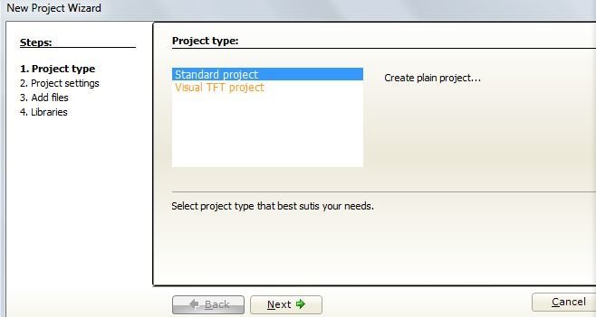
- “New Project Wizard” window opens. Select a standard project and click next. We can also create TFT based projects with the MikroC compiler. But in this tutorial, we will create a standard project only. After that click on “Next” button.
- Type Project Name, Folder where you want to save your project, your PIC MicroController device mine is P18F46K22 (for simulation you can use any but you will have to select the same in Proteus) and Device clock (set it to 32MHz). Then click Next. Before selecting frequency, always make sure from the microcontroller datasheet about the frequency it supports.

- Again click next. We don’t need to add any files. This option is used to add existing c-program files to your project. For instance, you already have a pic microcontroller code that you want to include in your new project. From this window, you can add this file to your new project. But for now, leave it as it is and go next.

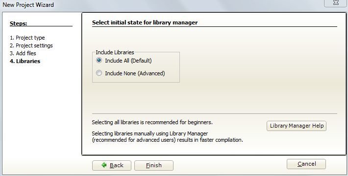
- As we mentioned earlier, the MikroC compiler supports many built-in libraries. By using this option, we can select libraries or you can include all libraries to your project. For instance, if you want to use ADC and UART communication modules only in your project, you can include libraries. But if you want to use your own libraries, you can select “Include None”. For now, select “Include all” libraries and click Finish.
- A window like shown below appears. This is place where we will write our program. You write everything inside this main program window.

Set Configuration Bits
In the mikroC compiler, it is very easy to set configuration bits. To set configuration bits. Go to projects at the menu bar and select the Edit Project as shown in figure below:

In the opened window select your MCU (MikroController name) and MCU clock frequency. Further, on the left panel, we can select settings for other configurations bits such as Oscillator selection, 4x PLL, Brown out Reset and MCLR pin. You should set these settings from the drop-down menu according to your requirement and then click OK.
Recommend Reading : Setting Configuration bits of Pic Microcontroller


Write Your First Program
Now that you know how to create a new project by selecting a specific microcontroller. It’s time to write our program. For demonstration, we will write our first program to turn a LED ON and OFF connected to the PIC18F46K22 microcontroller. As you know that all microcontroller has GPIO pins that can be used either as digital input or digital output pins. In this example, we will use GPIO pins of PIC18F46K22 microcontroller as a digital output. For further information on microcontroller GPIO pins, you can read this post:
How to use GPIO pins of Pic Microcontroller
In order to use any pin of PIC18F46k22 as a digital output, We need to set different registers to get this project work. We will discuss all of them one by one.TRIS register determines whether a port pin is an input or output pin. It can contain either a 0 or 1 value. For example, if we want to configure any PORT as a digital input pin, we set TRIS register value to ‘1’ and if we want to use as a digital output pin, we set TRIS register as logic ‘0’.
TRISx = 0x00;  //in hex format 0x00 means all bits of TRIS register 0 and as a output
TRISx = 0xFF;  //  configure as a input
When we use TRISB it is going to set whole port B i.e. (B0, B1, B2 …) as output. When we use TRISB1_bit it sets only B1 pin as an output.
Some pins of PIC18F46K22 microcontroller has multiple functions. For example, some of the pins of PORTB are also multiplexed with ADC channels. ANSEL register determines whether a port will be used as a digital pin or analog. It can contain either a 0 or 1 value. When we use ANSELB it’s going to set whole port B i.e. (B0, B1, B2 …) as DIGITAL.
ANSELB=0X00; //declares all PORTB pins as digial pinsLAT register is used to write a value on a port. When we use LATB it is going to write values on port B. We can give it a hex value like 0x00 will write 0 on port B and 0xFF will write 1 on the Port B. LAT register can contain both hex and decimal values i.e. writing only 0 instead of 0x00 will also set port B to be 0. If we want to set only pin B0 to high or low we will use LATB.B0
Delay_ms () produces the delay in milli seconds.
If you still have confusion on How LED blinking working with Pic microcontroller, you can read this complete tutorial:
LED Blinking using Pic Microcontroller
Example Code MikroC
Write the following code in software
void main()
 {  TRISB0_bit = 0; //set pin B0 as output
ANSEL = 0; //set port as Digital
 do  {
 LATB.B0 = 0; //write the pin B0 with 0 value
Delay_ms(1000); //Delay of 1 second
LATB.B0 = 1; //write the pin B0 with 1 value
Delay_ms(1000); //Delay of 1 second
}  while(1); //Keep the loop running
}
Compile Code with MikroC
After writing the code Build it from Menu bar. If everything is right it will display a message of finish successfully in the below window. After that go to the project folder where you saved your project and locate the hex file. Because we will use this hex file to program pic microcontroller.

After you get the hex fille, you can upload it to PIC18F46K22 microcontroller or use it in proteus. If you want to upload it to your actual hardware, you can use any programmer such as Pickit2, PicKit3. Check this tuorial to know how to upload code using PicKit3 programmer:
How to upload code using Pickit3 Burner?
Proteus Simulation
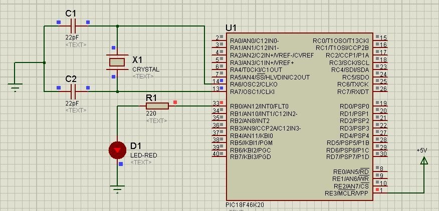
Draw circuit in Proteus as shown (Use same controller which you selected in software earlier). Set crystal frequency 8MHz by double clicking it and entering the frequency in dialogue box that appears.

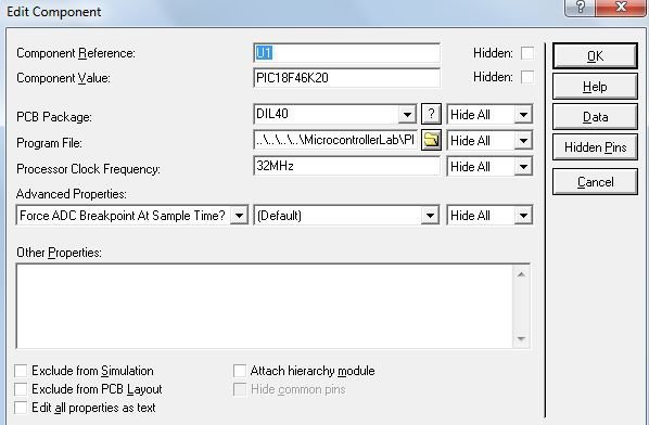
Double click the MikroController in Proteus a dialogue box appears as shown

Browse for Program file in box and give the path of .hex file created after building the program in MikroC software. It will be in same folder, where you saved the .c file. Also change the processor clock frequency to 32MHz.
Click on play button on the bottom of Proteus.

You will see that LED is blinking for 1 sec on Proteus window.
That’s all for this tutorial in our next tutorial we will see how to program our actual controller using PICKit3.
thi is intereting and inspiring-keep it up.
thanks
well yar it is excellent. great friend.
thankyou for helping us ,it is too usefull thing. I’m doing such work I need program,do you help me on this