In this tutorial, we will design a digital temperature sensor using LM35 sensor and PIC16F877A microcontroller. Unlike the previous posts, we will use 7-segment displays to print measured temperature values in the Celsius scale. You can use other types of temperature sensors also. This is also known as a digital thermometer with a seven-segment display. You can read our last tutorial where we used 16X2 LCD to print temperature using PIC16F877A microcontroller.
Recommended Components
The following components are used in this project or are helpful for building it with a PIC microcontroller.
| Component | How it’s used in this project | Buy on Amazon |
|---|---|---|
| PIC16F877A microcontroller | Host MCU that reads the LM35 and drives the 7-segment display. | Check Price |
| PICkit 5 programmer/debugger | Flashes the compiled firmware onto the PIC and debugs it. | Check Price |
| LM35 temperature sensor | Analog temperature sensor read by the PIC ADC in this project. | Check Price |
| Single-digit 7-segment display (common cathode) | Displays the measured temperature value digit by digit. | Check Price |
| Breadboard | Solderless base for wiring the PIC, sensor and display. | Check Price |
| Jumper Wires | Connect the analog, power and segment lines between parts. | Check Price |
As an Amazon Associate we earn from qualifying purchases. Prices and availability are accurate as of the date/time indicated and are subject to change.
Prerequisites
In order to completely understand the LM35 temperature sensor with 7-segment, you should have some basic background of PIC microcontroller features such as the ADC module and 7-segment displays interfacing with Pic microcontroller. Therefore, I recommend reading these posts:
- 7-Segment displays Interfacing with Pic Microcontroller
- How to use PIC Microcontroller ADC Module (This post helps you understand how to capture analog signals with PIC16F877A microcontroller. Because LM35 temperature sensor provides analog output)
LM35 Temperature Sensor Introduction
Let’s begin with the introduction of an LM35 temperature sensor. It provides temperature in the range of -55°C to 150°C. Furthermore, it supports a wide operating voltage range between -2 to 35 volts. But we usually use volts supply while interfacing with microcontrollers such as PIC16F877A. On top of these features, it draws only 60uA current and temperature accuracy is ±0.5°C .
Pinout Diagram
This picture shows the pinout diagram of LM35 temperature sensor. It consists of three terminals which makes it easy to use with microcontrollers.

Pin description is given in the table below:
| Pin Number | Name | Functionality |
| 1 | Vcc | Connect voltage supply to this pin (Usually 5 volts) |
| 2 | Vout | Output voltage pin ( Connect with Microcontroller ADC) |
| 3 | Ground | Ground reference |
How to convert output voltage into temperature?
Its output is analog voltage. Most importantly, output voltage and temperature are directly proportional to each other and response of sensor is linear. That means that the voltage on output pin rise linearly with respect to temperature surrounding. This equation is used to determine the correlation between output voltage and temperature:
1°C = 10mv
Above equation simply means that for every 10mV increase in output voltage there will be 1 degree increase in temperature. In other words, whenever, the temperature of surrounding rise by 1°C, the output voltage also increases by 10mV.
Hence, if we can compute output voltage of LM35 temperature sensor, we can convert it into temperature (degrees Celsius) by using above equation. Therefore, we rewrite above equation like this:
1mv = 1/10 degree Celsius
1v = 100 degree Celsius
For example, if the output voltage of LM35 temperature sensor is 225mv. Therefore, according to above equation, the temperature value is 22.5 degree Celsius.
LM35 Based Digital Thermometer Circuit diagram
This circuit diagram shows the connection between the LM35 temperature sensor, PIC16F877A microcontroller, and 4-digit seven-segment display. You should make connections according to this schematic and if you want to change pins, you should also make changes in the code. But do it only if you fully understand the interfacing circuit and program.
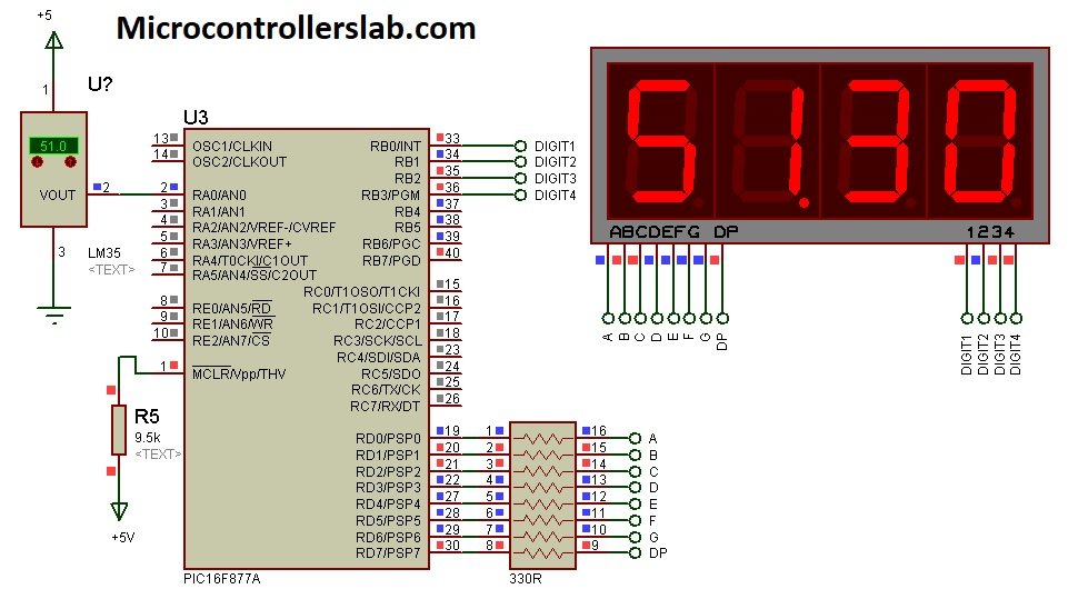
Connection between LM35 and PIC16F877A Microcontroller
We will use PIC16F877A microcontroller in this project. It has a built-in ADC module and each analog to digital converter channel is of 10-bit. That means it can measure a minimum voltage of 4.88mV which is less than 10mV. Hence, we can easily measure 10mV with ADC of PIC16F877A microcontroller without using any amplifier circuit. Because the minimum voltage that we can measure with PIC16F877A ADC is more than the two times the minimum voltage output of LM35 temperature sensor. Therefore, we do not require any interfacing circuit between temperature sensor and PIC16F877A microcontroller.
| PIC16F877A | LM35 |
| +5 Volts | Vcc |
| AN0/RA0 | Vout |
| Ground pin | Ground |
For further information on how to use PIC microcontroller ADC, read this article:
- How to use PIC Microcontroller ADC Module
Connection with 4-digit 7-segment display
As you can depict from above circuit diagram, We connected PORTD 8 pins from RD0-RD8 with a-g segments of 4-digit 7-segment display. Because we send display codes to each seven segment from microcontroller GPIO pins and also four control lines to select seven-segment digit.
We use four-digit 7-segment display. Because we want to print both decimal and fractional values of temperature. 4-digit display can print numbers between 0-9999. Hence, we will use two 7-segments to display decimal value and remaining two for printing fractional values.
Here we used pin multiplexing method to control four 7-segments with 7 GPIO pins of PIC16F877A microcontroller. If we do not use multiplexing method, we will need 7×4=28 pins to interface with PIC16F877A microcontroller. But it will be wastage of microcontroller GPIO pins and also not all pic microcontroller have that too many pins available. Hence, by using multiplexing method, we can save almost 16 GPIO pins of microcontroller and we can drive 4-digit 7-segment device with 12 pins only.
- 7 pins for a-g and one for dp
- 4 pins for common anode or common anode terminal of 7-segments.
Now make the connections of 4-digit seven-segment with PIC16F877A microcontroller according to this table:
| PIC16F877A PORTD | 4-digit 7-Segment display pins |
|---|---|
| RD0 | Segment-A |
| RD1 | Segment-B |
| RD2 | Segment-C |
| RD3 | Segment-D |
| RD4 | Segment-E |
| RD5 | Segment-F |
| RD6 | Segment-G |
| RD7 | DIP |
| PIC16F877A | 4-Digit Display pins |
|---|---|
| RB0 | 1 |
| RB1 | 2 |
| RB2 | 3 |
| RB3 | 4 |
To explore further on 7-segments displays interfacing and how to achieve multiplexing, you can read this in-depth guide:
- Interfacing 7-Segment displays with Pic Microcontroller
MikroC Code
This code is written using MikroC for Pic compiler. Create a new project with MikroC compiler by selecting PIC16F877A microcontroller and set frequency to 8MHz. If you don’t know how create new project in mikroC, we suggest you read this post:
// define name to each control signal for 7-segment
sbit digit1 at PORTB.B0;
sbit digit2 at PORTB.B1;
sbit digit3 at PORTB.B2;
sbit digit4 at PORTB.B3;
// This array stores binary bit pattern that will be send to PORTD
unsigned char binary_pattern[]={0x3F,0x06,0x5B,0x4F,0x66,0x6D,0x7D,0x07,0x7F,0x6F}; // without Dp turn
unsigned char display1[10]= {0xBF,0x86,0xDB,0xCF,0xE6,0xED,0xFD,0x87,0xFF,0xE7};    // with dp turn on

// variables to store digits, digital value and output voltage
unsigned int a1,a2,a3,a4; // temporary variables to store data of adc
int adc_value; //store output value from Analog Read functoion
unsigned int number;
long tlong;
unsigned int voltage;

// this function retrive each digita that will displayed on device
void get_digits()
  {
           a1 =  voltage / 1000u;   // holds 1000's digit
           a2 = ((voltage/100u)%10u); // holds 100's digit
           a3 = ((voltage/10u)%10u);  // holds 10th digit
           a4 = (voltage%10u);  // holds unit digit value
   }

// this function displays measured voltage on seven-segments
void display_voltage()
 {
            PORTD = binary_pattern[a2]; // send 1000's place data to fourth digit
            digit1 = 0;   //  turn on forth display unit
            delay_ms(3);
            digit1 = 1;   //  turn off forth display unit
            PORTD = display1[a3];  // send 100's place data to 3rd digit
            digit2 = 0;    //  turn on 3rd display unit
            delay_ms(3);
            digit2 = 1;  //  turn off 3rd display unit
            PORTD = binary_pattern[a4];  // send 10th place data to 2nd digit
            digit3 = 0;  //  turn on 2nd display unit
            delay_ms(3);
            digit3 = 1;   //  turn off 2nd display unit
            PORTD=binary_pattern[a1];  // send unit place data to 1st digit
            digit4 = 0;  //  turn on 1st display unit
            delay_ms(3);
            digit4 = 1;  //  turn off 1st display unit
   }
void interrupt()
{

            get_digits();   // call function to split data
            display_voltage(); //call display_data() function to output value to seven segment

            T0IF_bit = 0;  // clear source of timer0 interrupt
}
void main(void)
{
    TMR0   = 0;         // timer0 reset bit
    OPTION_REG = 0x83;  // select prescalar value 1:16 for timer0
    INTCON = 0xA0;      // turn on global interrupt and timer0 overflow interrupt
    TRISD = 0x00; //define PORTD as a output pin
    PORTD=0x00;   // initialize PORTD pins to active low
    TRISB=0x00;// Set PORTB as a output port
  // set control pins pins initially active high
    digit1 = 1;
    digit2 = 1;
    digit3 = 1;
    digit4 = 1;

    while(1)
    {

           adc_value = ADC_Read(0);  // read data from channel 0
           tlong = (float)adc_value*4.88768555; //converts voltage into temperature
           voltage = tlong;


    }

}
How code works?
The working of a digital temperature sensor with a 7-segment display code is the same as the working of the digital dc voltmeter project with 7-segment display. The only difference is the conversion of voltage into temperature.
First we start by defining RA0/AN0 pin of PIC16F877A microcontroller as an analog pin. This line reads output volage of LM35 temperature sensor and store its value inside a “adc_value” variable.
adc_value = ADC_Read(0); // read data from channel 0After that, we should convert ADC measured digital value into temperature. We multiply the adc_value variable with ‘4.88768555’. Here 4.88768555 comes from (5 x 1000) /1023. Here 5000/1023 converts the voltage into millivolts and again divided by 10 will get us a temperature value. Because of 10mv=1 degree celsius.
tlong = (float)adc_value*4.88768555; //converts voltage into temperature We define a global variable “voltage” that will be used to split data for each digit and print its value on a 7-segment display. This line stores the value of “tlong” in “voltage” variable. Global variables are defined when we want to use them anywhere in the whole program. Hence we can use “voltage” anywhere in the program.
voltage = tlong;Proteus Simulation
We used proteus simulation software to simulate this circuit. As you can observe from this circuit, as soon as we are changing temperature sensor value, PIC16F877A microcontroller outputs temperature sensor value on four digit 7-segment display.
MPLAB XC8 Code
This code is for MPLAB XC8 Compiler. If you don’t know how to use MPLAB and XC8 compiler, you can read this complete in-depth guide:
After creating a new project, set configuration bits by generating configuration bit file with MPLAB XC8. While generating this file, select the HS crystal option and leave the remaining setting as to default settings.
#include <xc.h>
#define _XTAL_FREQ 20000000 //define crystal frequency to 20MHz
#define digit1 PORTBbits.RB0
#define digit2 PORTBbits.RB1
#define digit3 PORTBbits.RB2
#define digit4 PORTBbits.RB3
// This array stores binary bit pattern that will be send to PORTD
unsigned char binary_pattern[]={0x3F,0x06,0x5B,0x4F,0x66,0x6D,0x7D,0x07,0x7F,0x6F};
unsigned char display1[10]= {0xBF,0x86,0xDB,0xCF,0xE6,0xED,0xFD,0x87,0xFF,0xE7};    // with dp turn on
unsigned int a1,a2,a3,a4;
unsigned int counter = 0;
int adc_value; //store output value from Analog Read functoion
unsigned int number;
long tlong;
unsigned int voltage;
void Analog_setting(){
    ADCON0 = 0x81;
    ADCON1 = 0x02;
}

unsigned int Analog_read(unsigned char channel){
    int aadc,bbdc, ccdc;
    if(channel>7)return 0;
    ADCON0 = ADCON0 & 0xC5;
    ADCON0 = ADCON0 | (channel << 3);
    __delay_ms(2);
    ADCON0bits.GO_DONE = 1;
    while(ADCON0bits.GO_DONE);
    aadc = ADRESH;
    aadc = aadc<<2;
    bbdc = ADRESL;
    bbdc = bbdc >>6;
    ccdc = aadc|bbdc;
    return ccdc;

}
void main(void)
{
    Analog_setting();
    TRISD = 0x00; //define PORTD as a output pin
    PORTD=0X00;   // initialize PORTD pins to active low
    TRISB=0X00;
    digit1 = 1;
    digit2 = 1;
    digit3 = 1;
    digit4 = 1;
    while(1)
    {
          adc_value = Analog_read(0);  // read data from channel 0
           tlong = (float)adc_value*4.88768555;
           voltage = tlong;

           a1 = voltage / 1000;   // holds 1000's digit
           a2 = ((voltage/100)%10); // holds 100's digit
           a3 = ((voltage/10)%10);  // holds 10th digit
           a4 = (voltage%10);  // holds unit digit value


PORTD=binary_pattern[a2]; // send 1000's place data to fourth digit
digit1=0;   //  turn on forth display unit
__delay_ms(3);
digit1=1;   //  turn off forth display unit
PORTD=display1[a3];  // send 100's place data to 3rd digit
digit2=0;    //  turn on 3rd display unit
__delay_ms(3);
digit2=1;  //  turn off 3rd display unit
PORTD=binary_pattern[a4];  // send 10th place data to 2nd digit
digit3 = 0;  //  turn on 2nd display unit
__delay_ms(3);
 digit3 = 1;   //  turn off 2nd display unit
PORTD=binary_pattern[a1];  // send unit place data to 1st digit
digit4 = 0;  //  turn on 1st display unit
__delay_ms(3);
digit4 = 1;  //  turn off 1st display unit


    }
    return ;
}
Please note down the 10ms delay function for pic 16f877a.
Hello, I am Hassan
I would like to thank you for your useful site
Please Make a LM35 Temperature Sensor with 7-Segment Display using Pic Microcontroller Nagetive Temperature..Please upload..
I want to display the speed of an engine with 7-segment displays who can give me an idea please