In this tutorial, we will introduce you to Reed switch, its working principle, interfacing with Arduino, and reading the switch through program sketches. A reed switch is basically an electrical switch which is operated when a magnetic field is brought near to it. It is constructed by using two small metal plates within a glass tube under a vacuum. When detecting the magnetic field the sheets come together and close the circuit. The switch will be activated when there will be magnetic field near it. Reed switch is basically used to detect the magnetic field.
In this tutorial, we will use this switch to light up a LED when a magnetic field will be detected. The basic difference between the reed switch module and mini reed switch module is that the reed switch module gives us both the analog and digital outputs while the mini reed switch gives us only digital output. We are going to discuss both.
What is Reed Switch?
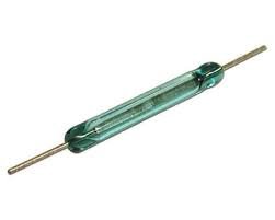
A Reed switch is basically an electronics device which consists of read contacts. It was used first time by a scientist Bell. Reed switch consists of two electrical contacts which are normally open. These electronics electrodes are made of copper or other electrically conductive materials. Normally these contacts are open. When we bring a magnet close to reed switch, these contacts close. So normally it will act like an open circuit and when it is place inside a magnetic filed it will act like close circuit by making contacts short with each other. The picture of reed switch is shown below.
Reed Switch Module
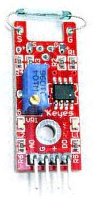
You can see that the reed switch module has a potentiometer that is used as a pull up resistor. The module also has an on board led which indicates that the reed switch has detected a magnet field or not. These are just used for the switching mechanism using electromagnetism. The reed switch module has both analog and digital output. So, we can use it in both ways. In this tutorial, we are going to use it in both ways.
Reed Switch Overview
A reed switch consists of two metals reeds composed of a ferromagnetic material. This material is of a special kind. It has the ability to quickly magnetize when in the presence of a magnetic field and on the same way quickly demagnetize in the absence of a magnetic field. Additionally, to ensure the longevity of the reed contacts, they are coated with resilient metals such as palladium, iridium, rhodium, or ruthenium. The switching speed of the reed contacts is comparatively low as that of electronic switches. It is 0.6ms for turn on time and 0.2ms for turn-off time.
The presence of a magnetic field is detected by a reed switch. When both contacts move in the presence of a magnetic field, they produce a parallel area of contact with each other. The reed switch’s life and dependability are extended as a result of this.

Moreover, as you may note in the diagram of the reed switch above, the reeds are enclosed in a glass capsule in an airtight manner. To avoid oxidation of the contacts, an inert gas (vacuum) is filled up inside the glass capsule.
Reed Switch Working
Now let us understand how a reed switch works. In a presence of a magnetic field, the two contacts of a reed switch act as opposite magnetic poles. Therefore they attract each other and join together. When the magnetic field is not present, the contacts return back to their initial positions. In that state, a reed switch is said to be open. It does not conduct electricity during that phase. However, in the presence of a magnetic field, the reed contacts join together and electricity flows through.
Reed switch Pinout
The pin out of the reed switch is as follows
A0: analog pin, this will be connected to the analog pin of Arduino.
G: ground, this will be connected to the ground of the Arduino.
+: 5V pin. This will be connected to 5V pin of the Arduino.
D0: Digital pin, this will be connected to any digital pin of the Arduino.
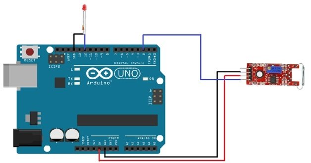
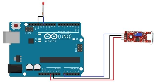
Reed Switch Interfacing with Arduino digital pin
The connections are very easier. We have connected the +5V and ground pin of the module with the +5v and the ground pin of the Arduino. Then we connected the digital of the module with the pin 2 of the Arduino. A led is attached at the pin 12 of the Arduino which will light up when the module will sense a magnetic field. While using the digital pin, we can change the threshold value by changing the resistance of potentiometer (rotating the top of potentiometer).
Code of reed switch with arduino
// This code is for testing the switch when using the digital pin
int Led_pin = 12 ;                                              // initializing the pin 12 as led pin

int Sensor_pin = 2 ;                                         // initializing the pin 2 sensor pin

int Value ;                                        // initializing a variable to store  sensor output

void setup ( )

{

  pinMode ( Led_pin, OUTPUT ) ;                               // declaring pin 12 as output pin

  pinMode ( Sensor_pin, INPUT ) ;            // declaring pin 2 as input pin

}

void loop ( )

SunFounder {

  Value = digitalRead ( Sensor_pin ) ;        // reading the sensor state

  if (Value == HIGH )                                        // If sensor pin is high then high the pin 12

  {

    digitalWrite ( Led_pin, HIGH ) ;

  }

  else

  {

    digitalWrite ( Led_pin, LOW ) ;                // Otherwise turn off or LOW

  }

}
Reed Switch Interfacing with Arduino analog pin
The connections are same like we used for digital pin excluding the use of digital pin is replaced by the analog pin. The Arduino gives us output from 0 to 1023 and we will show these values on the serial monitor.
Code of reed switch interfacing with arduino
// This code is for testing the switch when using the analog pin
int Sensor_pin = A0 ;                                                      // initializing A0 as sensor pin

int Led_pin = 12 ;                                                              // initializing pin 12 as led pin

int Value = 0 ;                                                                     // initializing a variable to store sensor value

void setup ( ) {

  pinMode ( Led_pin, OUTPUT ) ;                                               // declaring pin 12 as output pin

  Serial.begin ( 9600 ) ;                                                    // Setting baud rate at 9600

}

void loop ( ) {

  Value = analogRead ( Sensor_pin ) ;                      // reading from the sensor

  digitalWrite ( Led_pin, HIGH ) ;

  delay (Value ) ;

  digitalWrite ( Led_pin, LOW ) ;

  delay ( Value ) ;

  Serial.print( "SENSOR PIN A0:" )

  Serial.println ( Value, DEC ) ;                                                      // displaying the value on serial monitor

}
Mini Reed Switch
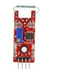
Unlike the switch which has both analog and digital output, mini reed switch has only one output.
Pin Out
The pin out of the mini reed switch from left to right is as follows.
S: signal pin
+5V: 5 volt pin
Gnd: ground pin
Code of mini reed switch interfacing with Arduino
// This code is for testing the mini reed switch
const int mini_reed_swtich_pin = 12;                                      // declaring pin 12 as the switch pin

const int led_pin = 9;                                                    // declaring pin 9 as the led pin

int store_value = 0;                                                         // variable to store the value

void  setup ( )  {

pinMode (led_pin, OUTPUT );                                                    // declaring led pin as output pin

pinMode (mini_reed_swtich_pin, INPUT );                          // declaring switch pin as input pin

}

void  loop () {

store_value = digitalRead (mini_reed_swtich_pin);               // reading from the sensor and storing

if (store_value == HIGH ) {                              // checks whether state of switch is high or not

digitalWrite (led_pin, HIGH );                             // turning on the led if the switch state is high

}

else {

digitalWrite (led_pin, LOW );                                                                       // Otherwise turning it low

}

}
You may also like to read:
Hi,
Im busy with a project where Im using Neopixel strip, Adafruit board and a mini Reed switch, and I need some help with the coding as I am still very new to this.
What I want to do is say for example:
if the switch is open, then LED 0 – 25 is white, if the switch is closed then LED 0 – 25 turns green.
What would the best way to code this be?