In this article, you will learn how to design PID controller using Arduino. PID controller can implemented using both analog and digital electronics. But in this tutorial, you will see the implementation of PID controller using Arduino development board. you will see it is very easy to design a proportional integral derivative controller using a microcontroller board like Arduino than using analog electronics. If you are reading this article, you surely know about feedback control system. Proportional integral derivative controller has many application in motor speed control, digital temperature controller and in many power electronics projects.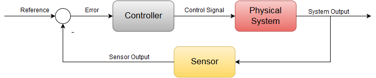
Introduction to PID controller
So let’s start off with the process. To understand PID controller, you first need to understand few concepts of feedback control system. A process in the control theory is a system whereby an applied input generates an output.So let’s take a visual system for example as our process. Our process consists of a throttle actuator which feeds fuel into the engine. Our input to the system is the angle of the gas pedal and our output is the speed or velocity of a vehicle. The greater the angle the faster the vehicle will go. The smaller the angle the slower the vehicle will go. This is an example of open loop control system.Now as far as this process is concerned, the driver’s actuation of the gas pedal is fully responsible for how slow or fast the vehicle will go. But what if we want to regulate speed at a constant velocity without actuating the gas pedal ourself ?
This is achieved using a closed loop feedback system commonly known as cruise control.To integrate cruise control to this process we will need to add a few more elements to the system block. First we start off by sensing the speed using a sensor or in this case a speedometer.The sensed speed the speedometer provides is compared with a set point or a desired speed to generate an error term.This error term is then fed into a controller which generates an actuation signal to drive the throttle and thus we have a feedback loop.

How PID controller works?
Now let’s say it’s some instance the vehicle is moving at 70 miles per hour. But we set our cruise control set point to 75. The actual speed is fed back and subtracted from our set point and we get a positive error of plus five. This positive error goes into the controller to generate a positive actuation signal to the throttle. Now this will allow more fuel into the engine and will cause the vehicle to go fast enough to reach the desired set point of 75 and our error will converge down to zero. This is the power of negative feedback control.
Now the same situation can happen vice versa where if the vehicle is going faster than our set point. So let’s say at 80 miles per hour. You’ll get a negative error term of negative 5. And thus our controller will provide a decrease throttle signal to slow down the vehicle back to 75. And again the error will converge down to zero. So it’s pretty apparent from this example that the controllers functionality is to essentially take our error signal and generate a control signal to drive our process. In doing so our actual output should eventually reach our desired set point and thus the error should converge down to zero.
What is the purpose of PID controller ?
Now the subject of this tutorial is to understand the famous controller used in most feedback control systems. The Proportional integral and Derivative controller or better known as the PID controller. The PID controllers job is to essentially take this error signal and perform three separate mathematical operations on it. Sum up the results and cleverly produce an output that will drive the system or process to the desired setpoint. The controller can be mathematically written out as shown where a control signal is a summation of three mathematical operations. The term involves taking the error and multiplying it by a constant Kp. The integral term involves integrating the error over time and the derivative term involves taking the derivative of the error.
Now you can see that each term has a constant in front of it. These are known as the tuning constants, and are the essential design parameters that if chosen properly will allow the controller to output a control signal that will bring the error down to zero. But when assessing a control system having the error term go down to zero is not the only goal. Because although you can adjust these parameters such that the error is driven to zero. Poor tuning of these constants can cause overshooting the desired set point, long settling time, and even in some cases instability or oscillations.
Proportional controller
Now I will discuss P or proportional term of the PID controller. As you see in block diagram of PID controller, the error essentially goes through each PID block and their outputs are summed up and form a control signal that drives the process to the desired setpoint. But in order to understand the advantage and disadvantage of using one or more term, we will break down the controllers operation by dealing with each term separately. Now lets see how a closed loop system performs with just proportional control. So let’s say we have a positive step change in the setpoint and therefore we get a positive error. Since all the P controller does is multiply the error by the control constant Kp. It’s quite apparent why this is known as proportional control because with a fixed Kp constant the control signal is proportional to the error. If our errors large, we’ll get a large control signal if our errors are small. we’ll get a small control signal. And thus we can adjust our control effort by simply increasing or decreasing this Kp constant.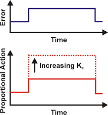
Main disadvantage of proportional control is that we can never drive the error to zero because that would mean our control effort is zero. Now there is a way to remove the offset or bring the error to zero. Looking at the normal structure of the controller if we were to add a bias signal to our controllers output, this can potentially drive the process enough such that we reach our desired setpoint. But the disadvantage of this method is that for every new set point we’re going to have to manually change the bias. Now although the proportional controller is easy to implement and can drive the process close to our setpoint, it can never eliminate the offset automatically. This issues can be automatically solved by adding integral controller.
Proportional Integral controller
It is used to mediates some of the flaws of the proportional controller. P controllers main flaw was its inability to bring the steady state error to zero. we have this steady state error AND we need a controller to somehow act on it in a way that will allow our control signal to accumulate until the desired setpoint is reached. This is easily achieved by taking the integral of the error. Let’s add the integral term to our original controller to form a PI controller.
The main advantage of integral control is that it allows us to eliminate the steady state error completely. Now by tuning the Ki term we can adjust the control effort of our integral controller. Now in this case for a high Ki value, we can see that we get a steeper slope and this would make our control signal more aggressive.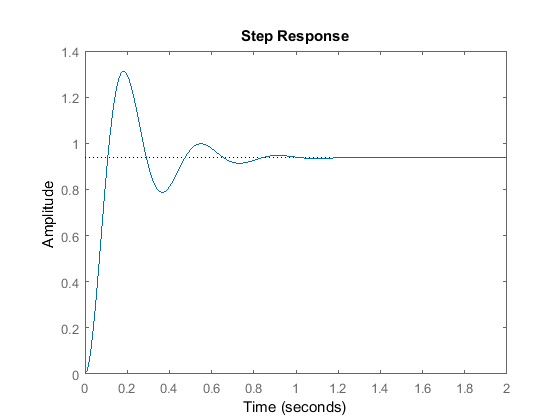
Now just like with proportional control, we can’t just arbitrarily choose an integral constant. The output behaves relatively upon varying the integral constant. If Ki is too low, we end up with the large rise time and overall a very slow response. This is bad when it comes to rejecting disturbances or constant changes in the set point. You can see we reached our set point much sooner with just a small amount of overshoot. But in an attempt to get a faster response, increasing this gain even further can lead to larger overshoots and this should be avoided when trying.
we learned that the proportional controller provided us with a fast rise time but with a steady state offset. The PI controller solves that using the integral control to reduce the error to zero. But when neither the controller can solve is the large overshoots and ringing. In order to reduce or dampen this response, we will need to add a differential controller and they’ll quickly respond fast enough to keep the output from overshooting or undershooting the set point.
Proportional integral derivative controller
We have seen that P controller eliminates the stay state error through the interval term. But we also made it clear that neither the p term or I term can contribute to actively dampening the overshoots. This is where the derivative comes into play. Let’s look at how this new term handles the error signal the job of the derivative term is to take the rate of change of the error as its control signal. The proportional term decreases the rise time the interval term eliminates a steady state error and the derivative term reduces the overshoots and ringing.

Now that we have understand PID controller and its three terms. Now lets see how to implement PID controller using Arduino.
Implementing PID controller using Arduino
Now, I’ll be going over how to implement a PID controller in code on the Arduino. The mathematical equation written here is a controller expressed in continuous time or in the analog domain.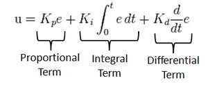
Now studying the controller in the continuous or analog domain makes it easier for us to realize what is going on. But most controllers these days are implemented digitally or with microcontroller like Arduino in software. So we want to implement this PID controller on the Arduino. We are going to have to convert it to the discrete time or digital domain as we can see here.
Not much has changed at all since we’re in the digital domain. We must treat each signal as a discrete sample. Because arduino will measure feedback signal in digital form. The proportional term is just the gain multiplied by the discrete error signal. The integral term is now a Sigma summation and the dreaded term is simply the difference between the current error and the previous error. Now in the digital domain graphically our control signal looks like this.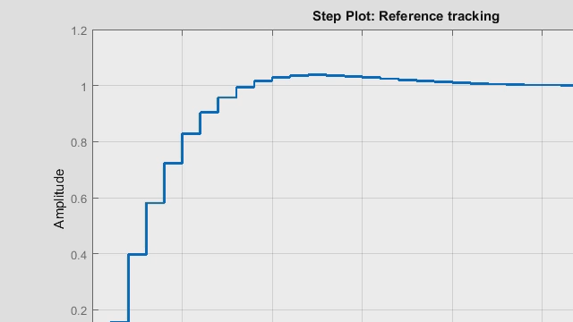
Now as you can see here to the control signal of N is computed discretely every t seconds in time. This case T is a sampling time or a fixed time interval. The controller takes to compute a new value for the output. And if we take a look at the discrete equation again this capital T is essentially the delta t of the continuous domain. Now because in the loop we’re going to call the function in intervals of t seconds. We can treat this as a fixed constant and this will be a lot clearer when I get to the coding part in Arduino IDE.
PID controller code for Arduino
So here we have the PID controller algorithm written out on the Arduino ID.
double sensed_output, control_signal;
double setpoint;
double Kp; //proportional gain
double Ki; //integral gain
double Kd; //derivative gain
int T; //sample time in milliseconds (ms)
unsigned long last_time;
double total_error, last_error;
int max_control;
int min_control;

void setup(){

}

void loop(){

PID_Control(); //calls the PID function every T interval and outputs a control signal

}

void PID_Control(){

unsigned long current_time = millis(); //returns the number of milliseconds passed since the Arduino started running the program

int delta_time = current_time - last_time; //delta time interval

if (delta_time >= T){

double error = setpoint - sensed_output;

total_error += error; //accumalates the error - integral term
if (total_error >= max_control) total_error = max_control;
else if (total_error <= min_control) total_error = min_control;

double delta_error = error - last_error; //difference of error for derivative term

control_signal = Kp*error + (Ki*T)*total_error + (Kd/T)*delta_error; //PID control compute
if (control_signal >= max_control) control_signal = max_control;
else if (control_signal <= min_control) control_signal = min_control;

last_error = error;
last_time = current_time;
}
}
I’ll now proceed to explain the code line by line. So first we start off by defining a variables needed for the computation. And you’ll notice most of these are of the double data type or floating point. This is needed because it allows more precise computation. Now just to make things easier I kept the computation of the control signal in a separate function called the control. Now in order to make sure that we get a uniform interval of sample time t we first start off by storing the current time the program has been running by using a built in function in Arduino IDE called millies. This function essentially gives you the number of milliseconds passed since the start of the program. we can keep track of the current time we can compute the delta time by subtracting the current time from the previous time now to get the updated control signal every t seconds.
we have an IF condition whereby if the time interval during the loop equals or exceeds t the control signal is computed and updated. This if condition is what allows the controller to get called FBT seconds and it makes realizing the controller a lot easier. Our error term is simply the set point minus the sensed output the total error refers to the integral term of accumulating the error. Every t seconds the Delta error refers to the derivative term whereas just a current error minus the last error. So what those values are computed and obtain a we can sum them up to form our control signal. And you can see here that the summation is pretty much the same as shown in the discrete expression. So what’s the control signals computed. We actually store the error as last error for the next iteration. And the same goes for the time. This pretty much covers how the control algorithm is implemented or on the order.
sir i want work on project
so i am looking for pid controller base project which should be cheap and easy
i want you help me sir
I play with similar code from ours. I notice that for microcontroler time calculation is not needed, because each itteration of program gives almost this same amount of time. And using this program for heating device, delta time is not needed.
Delta error do it’s job.
Delta time was needed to calculate boost for output. But when delta error is sustain for 15 iterations, then delta time stay at 0.
Delta time should be measured only to how fast error is going to zero, and then adjust output to slow it down.
We are interested in developing Arduino based PID controllers for some applications. Like to meet students / interns interested in developing them.
We are a start up company based in Trivandrum Kerala India
awesome!!!! I want to do something like this, but using freertos over stm32. Thanks!!!
you can apply the same concepts with STM32 also.
Hello Sir,
Please can you assist me in coming up with PID arduino controlled egg incubator with egg turner, temperature and humidity control etc.
I wish to control the orientation of a vane/fin in response to rotation of an object. I am using and IMU which outputs rotation in degrees/min about the z-axis. I use that data to control a servo that inversely changes the position of the vane to keep the object oriented in a particular direction. What I am unclear about is how I implement the PID to keep the correction of the vane down so the corrections are not gross or over controlling, setting up a resonance. I can provide code if you require.
question:
1. Why total_error as max/mix for control_signal reference? Why not using max/min value from control_signal computation.
2. Are there not using PWM as control_signal output, so we must write code like analogWite(PINout,control_signal) ?
3. Actually the error signal fluctuate so, we must make filter for it.
Thanks
Total error here accumulates the error over time. if its not capped at some min|max value its term in the control signal would still flood even if the control signal itself is held between the boundaries. Imagine the control signal is held at the max yet the total error is flying in the positive direction. when its time for the error to turn around you’ll expect the control signal to start discounting as well. but practically that won’t happen since by this time the total error value is still too large. thus it will take sweet time to wind down so that the control signal can appreciably turn around.
sangat tertarik akan penjelasan ini,bagaimana dengan pid dari diesel common rail ,terima kasih
I tried copy & paste this code exactly and set my variables as;
min_control = 10;
max_control = 250;
setpoint = 94.4;
Kp = 33;
Ki = 3;
Kd = 82;
sensed_output = 62;
Then I added;
Serial.println(sensed_output);
Serial.println(setpoint);
Serial.println(control_signal);
and the results I get in the Serial Monitor are;
62.00
94.40
nan
I’ve changed nothing else in the code. I simply wanted to get a calculated result before proceeding further, but obviously something is really weird with the control signal variable.
Your K factors are way too high. Consider range from 0.3 to 2.0 for these factors. There are some “rules of thumb” to setting PID factors you should look at.
also add error value
pls add set point which is minimize your error value so can you get accurate result
What are min_control and max_control ?also ideally what should be sample time (T)
Excellent write up! I did notice one thing every tutorial doesn’t mention that newbies might not be aware of. The frequency of measurements HAS to be fast enough to capture the behavior of the system. With a water tank thermostat it’s not an issue, if you’re trying to stabilize a quad-copter it’s an issue.
Thanks again,
Jay