In this tutorial, you will learn to use SPI communication port of Arduino. As an example, we will demonstrate SPI communication between two Arduino boards. It is a 4-wired serial communication protocol. It supports single master and multi slave communication. Therefore, in this tutorial, we will configure one Arduino as a master device and other board as a slave device.
SPI Introduction
Let’s start with the basic introduction of SPI protocol and its communication lines. This serial communication interface is also known as Serial Peripheral Interface. It provisions full duplex communication mode. It means data can be received and sent simultaneously. Master can send data to slaves and slaves can send data to master at same time. To transmit and receive data, a clock signal is required which means it is a synchronous communication channel.
If you want an in-depth detail on SPI communication protocol, you can read this tutorial:
This communication protocol uses four lines such as SCK, MOSI, MISO and SS. We will explain the details of these lines in the next section. Coming back to the main discussion, SPI bus can have a single master device and multiple slave devices. A master device is a microcontroller while slaves can be a microcontroller, ADC, DAC, etc.
Master Slave configuration Example
The figure given below shows the communication channel consisting of One Master and Four Slave devices.

Following four lines are used in SPI communication.
- SCK = Serial Clock = This line is used for clock pulses to synchronize data transmission from Master devices
- MOSI = Master Out Slave In = This line is used for sending data from Master device to Slave devices.
- MISO = Master In Slave Out = This line is used for sending data from Slave devices to Master device.
- SS = Slave Select = This pin is used by Master device to enable and disable specific devices to communicate with only some number of devices out of all.
Arduino SPI Pins
The figure below shows the pins in Arduino UNO which are used for SPI communication. These pins are highlighted in yellow color.

Following is the function performed by these pins.
- Pin11 = MOSI
- Pin12 = MISO
- Pin13 = SCK
- Pin10 = SS
SPI Communication in Arduino UNO
Now let’s see an example of SPI communication between two Arduino boards. But before that let’s understand the SPI communication library functions which are available in Arduino IDE.
SPI Library of Arduino
In order to establish communication between two Arduino using SPI, there is a pre-built library of Arduino used for this purpose
- <SPI.h>: It includes the library in the program to use the function of SPI communication.
- SPI.begin(): It initializes the SPI bus and sets the SCK and MOSI pin to LOW and SS pin to HIGH.
- SPI.transfer(val): This is used for simultaneous communication between Master and Slave devices.
- SPI.attachInterrupt(handler): It is used to receive data from a master device in a slave device and is called in a slave device.
- SPI.setClockDivider(divider): It set the SPI clock divider in accordance with the system clock.
Following types of divider are available here:
- SPI_CLOCK_DIV2
- SPI_CLOCK_DIV4
- SPI_CLOCK_DIV8
- SPI_CLOCK_DIV16
- SPI_CLOCK_DIV32
- SPI_CLOCK_DIV64
- SPI_CLOCK_DIV128
These dividers correspond to division with values of 2, 4, 8, 16, 32, 64, 128.
SPI Communication Between Two Arduinos
Now let’s see how to perform SPI communication between two Arduino boards.

We will configure one Arduino as a master device and another Arduino board as a slave device. A master device will transmit 1 if the user pressed the push button which is connected with the D2 of Arduino. SPI Slave Arduino receives this data and based on received data make a decision to turn-on or turn-off LED which is connected with the D4 pin of Arduino.
Connection Diagram
You will require the following components for this project:
Required Components
- Two Arduino UNO
- Two 5mm LEDs
- Two Pushbuttons
- Two 220 ohm resistors
- Two 10k ohm resistors
- Connecting Wires
- Breadboard
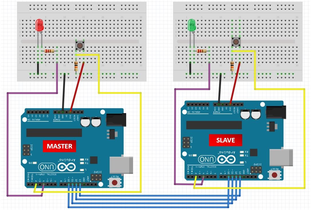
- In the above circuit diagram, for both the Master and the Slave, Arduino digital pin 4 is connected with anode pin of LED through a 220 ohm current limiting resistor. The cathode pin is grounded.
- Next, the push button’s one terminal is connected with 3.3 volts of Arduino and other terminals of a push button is connected with Arduino digital pin 4 through 10k pull-down resistor. The other end of the resistor is connected with a ground. When pushbutton is not pressed, logic low will appear on pin 4 or push button state will be low and when the push button is pressed, a logic high will be on pin 4.
- To enable SPI communication between the two boards, connect the SPI pins of master Arduino with the SPI pins of the slave Arduino.
Now let us understand the code of the Master device.
Arduino SPI Master Device Code
Code can be divided into 3 parts:
Declarations
In this section, we have included the SPI library and defined different variables. Push variables are the Arduino digital I/O pin where the push button will be connected and depending upon its status, Data will be transmitted to the slave device. LED variable is the Arduino pin where based on data received from slave device output status will be shown.
#include<SPI.h>
#define push 2
#define LED 4
int x;
int value;
Setting up the Device
Here device is being setup for program and communication. First baud rate has been set. The push and LED pins have been declared as input and output pins. Then SPI communication has been setup using functions described above and slave select has been set high to discontinue the communication if being performed already.
Serial.begin(115200);
pinMode(push,INPUT);
pinMode(LED,OUTPUT);
SPI.begin();
SPI.setClockDivider(SPI_CLOCK_DIV8);
digitalWrite(SS,HIGH);
Function performed
In this section we have performed actual operation on instruction sending and receiving.
byte m_send,m_receive;

  value = digitalRead(push);

  if(value == HIGH)
  {
    x = 1;
  }
  else
  {
    x = 0;
  }

  digitalWrite(SS, LOW);

  m_send = x;
  m_receive=SPI.transfer(m_send);

  if(m_receive == 1)
  {
    digitalWrite(LED,HIGH);
  }
  else
  {
   digitalWrite(LED,LOW);
  }
  delay(1000);
}
Two variables are defined m_send and m_receive. Status of push button attached at pin 2 is read. Depending upon status HIGH or LOW, command 1 or 0 is sent to slave using SPI.transfer function described above.
The next portion deals with the receiving of data. Data is also received using the same function SPI.transfer. If the received data is 0, LED at pin 4 is set to LOW and if received data is 1, LED at pin 4 is set HIGH.
Complete Master Device Code
#include<SPI.h>
#define push 2
#define LED 4

int x;
int value;

void setup (void)

{
  Serial.begin(115200);

  pinMode(push,INPUT);
  pinMode(LED,OUTPUT);

  SPI.begin();
  SPI.setClockDivider(SPI_CLOCK_DIV8);
  digitalWrite(SS,HIGH);
}

void loop(void)
{
  byte m_send,m_receive;

  value = digitalRead(push);

  if(value == HIGH)
  {
    x = 1;
  }
  else
  {
    x = 0;
  }

  digitalWrite(SS, LOW);

  m_send = x;
  m_receive=SPI.transfer(m_send);

  if(m_receive == 1)
  {
    digitalWrite(LED,HIGH);
  }
  else
  {
   digitalWrite(LED,LOW);
  }
  delay(1000);
}
Arduino SPI Master Device Code
Code can be divided into 3 parts:
Declarations
In this section we have included the SPI library and defined different variables. Inputbutton variable is the Arduino digital I/O pin where push button will be connected and depending upon its status, Data will be transmitted to master device. outputLED variable is the Arduino pin where based on data received from master device output status will be shown. Slave received will store value received from Master device.
#include<SPI.h>
#define inputbutton 2
#define outputLED 4

volatile boolean received;
volatile byte Slavereceived,Slavesend;
int buttonvalue;
int x;
Setting up the Device
Here device is being set up for program and communication. First baud rate has been set. The push and LED and MISO pins have been declared as input and output pins. Then the device has been set in slave mode and the interrupt has been set for SPI communication.
Serial.begin(115200);

  pinMode(inputbutton,INPUT);
  pinMode(outputLED,OUTPUT);
  pinMode(MISO,OUTPUT);

  SPCR |= _BV(SPE);
  received = false;

  SPI.attachInterrupt();
Whenever an interrupt occurs due to the SPI receiver pin, this interrupt service routine will execute.
ISR (SPI_STC_vect)
{
  Slavereceived = SPDR;
  received = true;
}
Function performed
In this section, we have performed actual operations on instruction sending and receiving.
if(received)
   {
      if (Slavereceived==1)
      {
        digitalWrite(outputLED,HIGH);
      }else
      {
        digitalWrite(outputLED,LOW);
      }

      buttonvalue = digitalRead(inputbutton);

      if (buttonvalue == HIGH)
      {
        x=1;

      }else
      {
        x=0;
      }

  Slavesend=x;
  SPDR = Slavesend;
  delay(1000);
Here first data receiving is confirmed if data is received then it is checked wither it is 0 or 1. If 0 is received, LED at output pin 4 is set to LOW and if 1 is received, LED at output pin 4 is set to HIGH.
Next portion deals with status checking of pus button pin 2 if status id HIGH, 1 is sent to Master and if the status is LOW, 0 is sent to Master device.
Complete Slave Device Code
#include<SPI.h>
#define inputbutton 2
#define outputLED 4

volatile boolean received;
volatile byte Slavereceived,Slavesend;
int buttonvalue;
int x;

void setup()

{
  Serial.begin(115200);

  pinMode(inputbutton,INPUT);
  pinMode(outputLED,OUTPUT);
  pinMode(MISO,OUTPUT);

  SPCR |= _BV(SPE);
  received = false;

  SPI.attachInterrupt();

}

ISR (SPI_STC_vect)
{
  Slavereceived = SPDR;
  received = true;
}

void loop()
{
 if(received)
   {
      if (Slavereceived==1)
      {
        digitalWrite(outputLED,HIGH);
      }else
      {
        digitalWrite(outputLED,LOW);
      }

      buttonvalue = digitalRead(inputbutton);

      if (buttonvalue == HIGH)
      {
        x=1;

      }else
      {
        x=0;
      }

  Slavesend=x;
  SPDR = Slavesend;
  delay(1000);
}
}
Hardware Demonstration
To see the demonstration of the above code, upload the master and slave code to the respective Arduino boards. But, before uploading code, make sure to select the Arduino board from Tools > Board and also select the correct COM port to which the Arduino board is connected from Tools > Port.

Now press the pushbutton of master Arduino and the slave Arduino’s LED turns ON. Likewise, press the pushbutton of the slave Arduino and the master Arduino’s LED turns ON.
Watch the video demonstration below:
Proteus Simulations
The following figure shows the normal state of communication when no button is pushed.

When button is pushed at Arduino 1, after some time (bear for some time) LED at Arduino 2 is turned ON. This delay is due to limitations of simulation resources of Proteus and PC.

When button is pushed at Arduino 2, after some time (Have patience to observe result) LED at Arduino 1 is turned ON. This delay is due to limitations of simulation resources of Proteus and PC.

SPI Applications in Arduino Projects
- SPI communication is used for interfacing a flash, memory card and EEPROM with microcontrollers
- OLED and LCD display uses this method for communication with embedded devices. Different sensors like temperature, pressure and DAC uses this mode of communication.
Check these more SPI communication related tutorials:
- SPI Communication Between Tiva Launchpad and Arduino
- PIC to PIC SPI communication with DC motor control
- SPI Communication with PIC microcontroller
- MCP3008 8-Channel 10-Bit A/D Converters with SPI Serial Interface
- Serial/UART Communication Between Two Arduino Boards
- ESP32 SPI Tutorial Master Slave Communication Example
Slave code has an error:
Compilation error: expected constructor, destructor, or type conversion before ‘(‘ token