In this tutorial, we will learn to use SPI communication buses of ESP32. By using that, we will see how to perform master slave SPI communication with ESP32 boards using Arduino IDE. Furthermore, we will look into SPI pins, how to use multiple SPI bus interfaces supported by ESP32, and how to configure them.
Recommended Components
The following components are used in this project or are helpful for building it with the ESP32.
| Component | How it’s used in this project | Buy on Amazon |
|---|---|---|
| ESP32 Development Board | Two boards act as the SPI master and slave for this communication example. | Check Price |
| Micro USB Cable | Connects each ESP32 to your computer for programming and power. | Check Price |
| Breadboard | Lets you wire the SPI connections without soldering. | Check Price |
| Jumper Wires | Connect the MOSI, MISO, SCLK and CS lines between the two boards. | Check Price |
As an Amazon Associate we earn from qualifying purchases. Prices and availability are accurate as of the date/time indicated and are subject to change.
SPI Communication Introduction
SPI stands for serial peripheral interface. It is a serial Full duplex and synchronous interface. The synchronous interface means it requires a clock signal to transfer and receive data. The clock signal is synchronized between both master and slave. Unlike UART communication which is asynchronous, the clock signal controls when data is to be sent to the slave and when it should be ready to read.
Only a master device can control the clock and provide a clock signal to all slave devices. Data can not be transferred without a clock signal. Both master and slave can exchange data with each other.No address decoding are done.
SPI Connection Between Two Devices
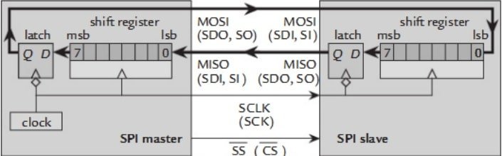
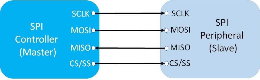
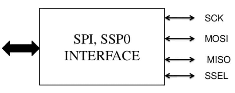
Both Master and Slave can exchange data with each other on the rising and falling edge of the clock signal. The Block diagram below shows interfacing with one Master and one Slave. SPI interface consists of either three or four signals. But generally, we will see a 4 wire interface, and the fourth wire is used to select a slave.
The functionality of each signal is given here.
- SCLK or SCK pin: This signal provides a clock to Slaves and only Master can control clock signal. Note that this pin remains in an idle state. i.e. inactive or tri-state when no operation is carried out.
- SS or CS: This is known as a chip select or Slave select pin. This line selects the slave to which the Master wants to transfer data.
- MOSI: It is a unidirectional pin. This stands for Master output and Slave input pin. As its name suggests, this line is used to send data from master to slave.
- MISO: This is known as Master input and a Slave output. This line is used to send data from the slave to the Master.
In short, in this communication protocol, devices exchange data in master/slave mode. The master device is mainly responsible for the initiation of the data frame. The master device also selects the slave device to which data need to be transferred. The chip select line is usually used to identify or select a particular slave device.
Whenever a master device read to transmit data to a slave or wants to receive data from the slave, the master does so by activating the clock signal from active low to active high state. Every master device sends data on the MOSI line and receives data through another line which is MISO.
ESP32 SPI Communication Bus
The ESP32 has four SPi buses but only two are available to use and they are known as HSPI and VSPI. As we mentioned earlier, in SPI communication, there is always one controller (which is also known as a master) which controls other peripheral devices ( also known as slaves).
We can configure ESP32 either as a master or slave. We will see examples of each of them at the end of this article.
As mentioned earlier, SPI is a full-duplex communication that means both master and slave can data to each other simultaneously.
We can use the ESP32 SPI controller to interface with many slave peripherals or devices such as SD cards, BME680, BME280, and any other sensor which provides data over SPI interface.
ESP32 SPI Pins
As discussed earlier, ESP32 has four SPI channels such as SPI0, SPI1, SPI2, and SPI3. But SPI0 and SP1 are not available to use. Because they are internally connected to communicate with the flash memory of the chip.
By default, ESP32 has two useable SPI communication channels SPI2 (HSPI) and SPI3 (VSPI) and the following table provides the default SPI pins for both channels. But if we can also map these pins to other GPIO pins also in Arduino or esp-idf.
| SPI Channel | MOSI / SDI | MISO / SDO | SCK/CLK | CS/SS |
|---|---|---|---|---|
| VSPI | GPIO23 | GPIO19 | GPIO18 | GPIO5 |
| HSPI | GPIO13 | GPIO12 | GPIO14 | GPIO15 |
Both VSPI and HSPI have separate bus signals. Hence, we can use them separately either as a master or slave. In controller mode, each bus can control up to three SPI devices or slaves.
Find ESP32 Board Default SPI Pins
Note: There are many types of ESP32 boards available. Your ESP32 board might have different default SPI pins. You can find information about default pins from their datasheet. But if default pins are not mentioned, we can find them using an Arduino sketch.
Copy the following code to Arduino IDE and upload it to your ESP32 board:
void setup() {
// put your setup code here, to run once:
Serial.begin(115200);
Serial.print("MOSI Pin: ");
Serial.println(MOSI);
Serial.print("MISO Pin: ");
Serial.println(MISO);
Serial.print("SCK Pin: ");
Serial.println(SCK);
Serial.print("SS Pin: ");
Serial.println(SS);
}
void loop() {
// put your main code here, to run repeatedly:
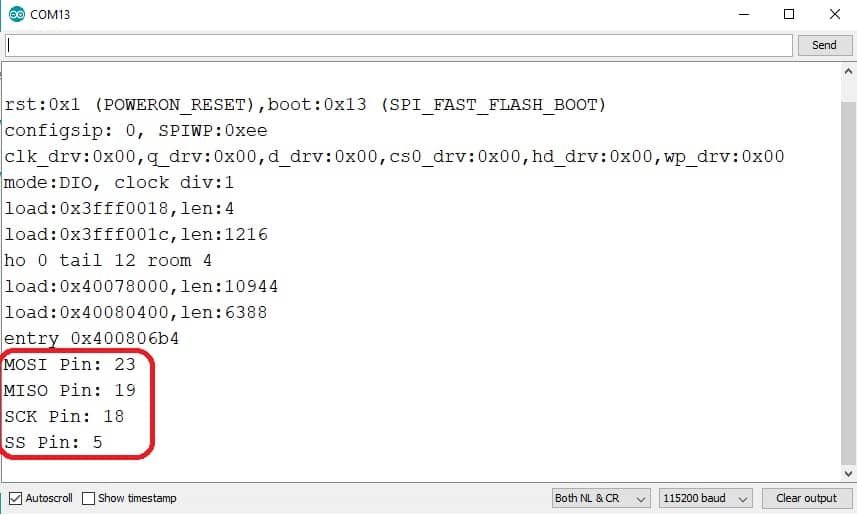
}Make sure to select your board from Tool>Boards. After uploading the above code, open the serial monitor and click on the reset button of the ESP32 board:

As soon as you press the enable/reset button, you will be able to see default SPI pin numbers on the serial monitor:
Use ESP32 SPI as a Master (Controller)
In this section, we will see how to use ESP32 SPI as a master to read data from a BME680 device which acts as a slave.
In the following schematic diagram, ESP32 connects with BME680 by using default SPI pins.
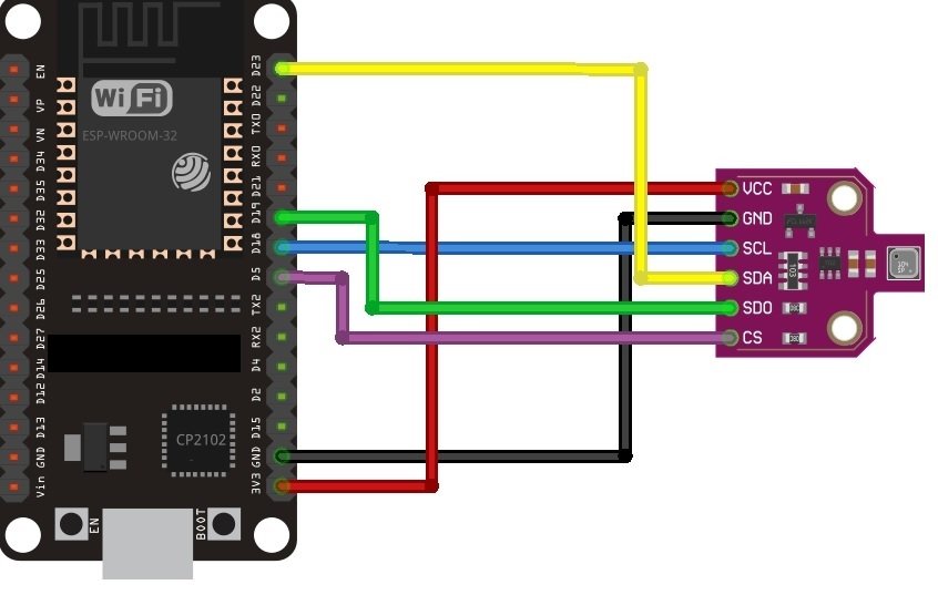
| BME680 | ESP32 |
|---|---|
| VCC | VCC=3.3V |
| GND | GND |
| SCL (SCK for SPI) | GPIO18 |
| SDA (SDI / MOSI for SPI) | GPIO23 |
| SDO / MISO | GPIO19 |
| CS | GPIO5 |
In the following example code, ESP32 acts as a master and gets BME680 sensor data over SPI communication. You can refer to this article for a complete guide of ESP32 with BME680:
#include <Wire.h>
#include <SPI.h>
#include <Adafruit_Sensor.h>
#include "Adafruit_BME680.h"


#define SEALEVELPRESSURE_HPA (1013.25)

//Adafruit_BME680 bme; // I2C
 Adafruit_BME680 bme(SS); // hardware SPI
 Adafruit_BME680 bme(SS, MOSI, MISO, SCK);

void setup() {
  Serial.begin(115200);
  while (!Serial);
  Serial.println(F("BME680 async test"));

  if (!bme.begin()) {
    Serial.println(F("Could not find a valid BME680 sensor, check wiring!"));
    while (1);
  }

  // Set up oversampling and filter initialization
  bme.setTemperatureOversampling(BME680_OS_8X);
  bme.setHumidityOversampling(BME680_OS_2X);
  bme.setPressureOversampling(BME680_OS_4X);
  bme.setIIRFilterSize(BME680_FILTER_SIZE_3);
  bme.setGasHeater(320, 150); // 320*C for 150 ms
}

void loop() {
  // Tell BME680 to begin measurement.
  unsigned long endTime = bme.beginReading();
  if (endTime == 0) {
    Serial.println(F("Failed to begin reading :("));
    return;
  }
  Serial.print(F("Reading started at "));
  Serial.print(millis());
  Serial.print(F(" and will finish at "));
  Serial.println(endTime);

  Serial.println(F("You can do other work during BME680 measurement."));
  delay(50); // This represents parallel work.
  // There's no need to delay() until millis() >= endTime: bme.endReading()
  // takes care of that. It's okay for parallel work to take longer than
  // BME680's measurement time.

  // Obtain measurement results from BME680. Note that this operation isn't
  // instantaneous even if milli() >= endTime due to I2C/SPI latency.
  if (!bme.endReading()) {
    Serial.println(F("Failed to complete reading :("));
    return;
  }
  Serial.print(F("Reading completed at "));
  Serial.println(millis());

  Serial.print(F("Temperature = "));
  Serial.print(bme.temperature);
  Serial.println(F(" *C"));

  Serial.print(F("Pressure = "));
  Serial.print(bme.pressure / 100.0);
  Serial.println(F(" hPa"));

  Serial.print(F("Humidity = "));
  Serial.print(bme.humidity);
  Serial.println(F(" %"));

  Serial.print(F("Gas = "));
  Serial.print(bme.gas_resistance / 1000.0);
  Serial.println(F(" KOhms"));

  Serial.print(F("Approx. Altitude = "));
  Serial.print(bme.readAltitude(SEALEVELPRESSURE_HPA));
  Serial.println(F(" m"));

  Serial.println();
  delay(2000);
}
As you can see in the above code, we are using default SPI pins to initialize BME680 object.
 Adafruit_BME680 bme(SS); // hardware SPI
 Adafruit_BME680 bme(SS, MOSI, MISO, SCK);
Use ESP32 Custom SPI Pins
We can also easily define custom pins for any ESP32 SPI bus instead of using default pins. When we are using libraries of sensors in Arduino IDE, it is very easy to define custom pins. But later on, we will also see how to define custom pins in the ESP32 SPI library.
We can define custom pins by passing pin names to the library constructor as here we passed pin numbers to BM680 library constructor:
#define BME_SCK  25
#define BME_MISO 32
#define BME_MOSI 26
#define BME_CS 33

Adafruit_BME680 bme(BME_CS); // hardware SPI
Adafruit_BME680 bme(BME_CS, BME_MOSI, BME_MISO, BME_SCK);
If you are not using any sensor library and you directly want to use SPI library, in that case, you can set the custom pins as follows. In the following code, we are using default pins for HSPI and custom pins for the VSPI bus.
#include <SPI.h>

#define VSPI_MISO   2
#define VSPI_MOSI   4
#define VSPI_SCLK   0
#define VSPI_SS     33

void setup()
{
vspi = new SPIClass(VSPI);
hspi = new SPIClass(HSPI);

 vspi->begin();
 vspi->begin(VSPI_SCLK, VSPI_MISO, VSPI_MOSI, VSPI_SS); //SCLK, MISO, MOSI, SS)
}
Use ESP32 SPI Master with Multiple SPI Slaves
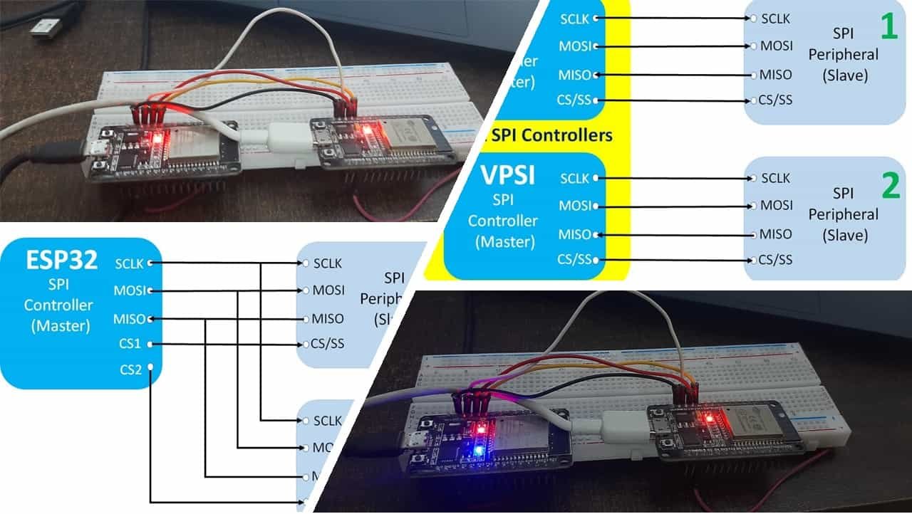
In this section, we will see how to use ESP32 SPI Bus with multiple SPI slave devices. To use a single SPI master with multiple slaves, we require multiple chip select (CS) or slave select (SS) lines from the controller(master).
As you can see in the following diagram, there is one ESP32 SPI controller and two SPI slave devices are connected with it by using the same MOSI, MISO, and SCLK pins. But different chip select lines are used for each slave device such as CS1 and CS2.
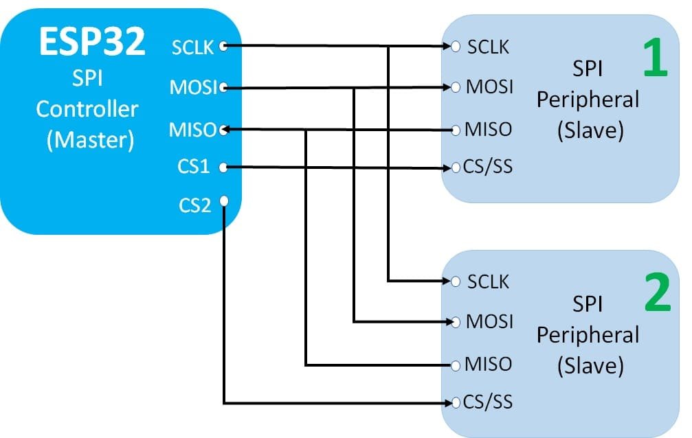
In our Arduino sketch, we make the particular CS line active low to select the slave device we want to communicate with.
For example, if we want to communicate with SPI peripheral 2, we will select it by setting the CS2 line to active low. Moreover, we should also make sure all other chip select lines should be active high on the SPI bus. Hence, in the above example, CS1 should be active high and CS2 must be active low when we want to communicate with SPI peripheral 2.
In summary, when using multiple slave devices with a single SPI master controller, we can communicate with a single slave device at a time and other slave devices will be in an idle state. If we want to communicate with multiple SPI devices simultaneously, we need to use multiple SPI controllers.
Use Two ESP32 SPI Buses HSPI and VSPI simultaneously
As discussed earlier, ESP32 has two usable SPI buses that are HSPI and VSPI. We can use them separately. As you can see in the following diagram, we have two SPI peripherals connected with HSPI and VSPI.

We have already seen default pins for HSPI and VSPI buses in the ESP32 SPI pins section. But we can use either default or custom pins for both.
Now let’s see how to configure, initialize and use HSPI and VSPI buses in Arduino sketch.
First, include the header file of ESP32 SPI Controller library.
#include <SPI.h>
Note: This library can configure ESP32 in master mode only. In the next section, we will see how to use ESP32 SPI as a slave and we install a separate ESP32 SPI slave library.
In SPI master library, SPIClass contains all function definitions to configure and use SPI buses. Create two objects of SPIClass with any name. Here, we have defined two objects with the names vpsi_controller and hspi_controller. and passed the names of both SPI controllers to a class constructor. One for each ESP32 SPI controller.
vspi_controller = new SPIClass(VSPI);
hspi_controller = new SPIClass(HSPI);
In last step, we created objects but SPIClass constructor only configured the SPI controller. To initialize and start SPI communication, call the begin() method on vspi_controller and hspi_controller objects. It will initialize and make controller ready to use on default SPI pins.
vspi_controller->begin();
hspi_controller->begin();
We can also pass custom pin numbers to begin() method if we want to use custom pins instead. For example:
#define VSPI_MISO   2
  #define VSPI_MOSI   4
  #define VSPI_SCLK   0
  #define VSPI_SS     33

  #define HSPI_MISO   26
  #define HSPI_MOSI   27
  #define HSPI_SCLK   25
  #define HSPI_SS     32

vspi->begin(VSPI_CLK, VSPI_MISO, VSPI_MOSI, VSPI_SS);
hspi->begin(HSPI_CLK, HSPI_MISO, HSPI_MOSI, HSPI_SS);
When we are using custom pins, we also need to declare CS/SS pins as output pins inside the setup().
pinMode(VSPI_SS, OUTPUT);
pinMode(HSPI_SS, OUTPUT);
You can refer to this ES32 SPI multiple bus example Arduino sketch. By using this sketch, we will perform SPI communication between two Arduino boards in the next section.
#include <SPI.h>

// Define ALTERNATE_PINS to use non-standard GPIO pins for SPI bus

#ifdef ALTERNATE_PINS
  #define VSPI_MISO   2
  #define VSPI_MOSI   4
  #define VSPI_SCLK   0
  #define VSPI_SS     33

  #define HSPI_MISO   26
  #define HSPI_MOSI   27
  #define HSPI_SCLK   25
  #define HSPI_SS     32
#else
  #define VSPI_MISO   MISO
  #define VSPI_MOSI   MOSI
  #define VSPI_SCLK   SCK
  #define VSPI_SS     SS

  #define HSPI_MISO   12
  #define HSPI_MOSI   13
  #define HSPI_SCLK   14
  #define HSPI_SS     15
#endif

static const int spiClk = 1000000; // 1 MHz

//uninitalised pointers to SPI objects
SPIClass * vspi = NULL;
SPIClass * hspi = NULL;

void setup() {
  //initialise two instances of the SPIClass attached to VSPI and HSPI respectively
  vspi = new SPIClass(VSPI);
  hspi = new SPIClass(HSPI);

  //clock miso mosi ss

#ifndef ALTERNATE_PINS
  //initialise vspi with default pins
  //SCLK = 18, MISO = 19, MOSI = 23, SS = 5
  vspi->begin();
#else
  //alternatively route through GPIO pins of your choice
  vspi->begin(VSPI_SCLK, VSPI_MISO, VSPI_MOSI, VSPI_SS); //SCLK, MISO, MOSI, SS
#endif

#ifndef ALTERNATE_PINS
  //initialise hspi with default pins
  //SCLK = 14, MISO = 12, MOSI = 13, SS = 15
  hspi->begin();
#else
  //alternatively route through GPIO pins
  hspi->begin(HSPI_SCLK, HSPI_MISO, HSPI_MOSI, HSPI_SS); //SCLK, MISO, MOSI, SS
#endif

  //set up slave select pins as outputs as the Arduino API
  //doesn't handle automatically pulling SS low
  pinMode(VSPI_SS, OUTPUT); //VSPI SS
  pinMode(HSPI_SS, OUTPUT); //HSPI SS

}

// the loop function runs over and over again until power down or reset
void loop() {
  //use the SPI buses
  vspiCommand();
  hspiCommand();
  delay(100);
}

void vspiCommand() {
  byte data = 0b01010101; // junk data to illustrate usage

  //use it as you would the regular arduino SPI API
  vspi->beginTransaction(SPISettings(spiClk, MSBFIRST, SPI_MODE0));
  digitalWrite(VSPI_SS, LOW); //pull SS slow to prep other end for transfer
  vspi->transfer(data);
  digitalWrite(VSPI_SS, HIGH); //pull ss high to signify end of data transfer
  vspi->endTransaction();
}

void hspiCommand() {
  byte stuff = 0b11001100;

  hspi->beginTransaction(SPISettings(spiClk, MSBFIRST, SPI_MODE0));
  digitalWrite(HSPI_SS, LOW);
  hspi->transfer(stuff);
  digitalWrite(HSPI_SS, HIGH);
  hspi->endTransaction();
}
ESP32 SPI Master Slave Communication Example
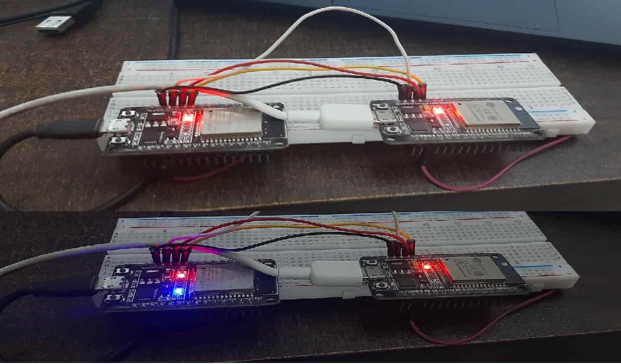
In this section, we will see an example to perform SPI communication between two ESP32 boards. We will configure one EPS32 as a master and another ESP32 as a slave.
We will transmit commands from the ESP32 controller to slave device to control its onboard LED. Master will transmit ‘0’ and ‘1’ with a delay of 1 second. ESP32 slave will receive it and turn on and off its onboard LED.
In the following examples, we have used HPSI bus and default pins for both master and slave. Take two ESP32 boards and make connections between them according to the table connection shown below:
| ESP32 Master | ESP32 Slave |
|---|---|
| MOSI (GPIO12) | MOSI (GPIO12) |
| MISO (GPIO13) | MISO (GPIO13) |
| SCLK (GPIO14) | SCLK (GPIO14) |
| CS (GPIO15) | CS (GPIO15) |
ESP32 SPI Master Sketch
This Arduino sketch will transfer on and off bytes on SPI bus using the HSPI controller with a delay of one second.
#include <SPI.h>

// Define ALTERNATE_PINS to use non-standard GPIO pins for SPI bus

#ifdef ALTERNATE_PINS
  #define HSPI_MISO   26
  #define HSPI_MOSI   27
  #define HSPI_SCLK   25
  #define HSPI_SS     32
#else
  #define HSPI_MISO   MISO
  #define HSPI_MOSI   MOSI
  #define HSPI_SCLK   SCK
  #define HSPI_SS     SS
#endif

static const int spiClk = 1000000; // 1 MHz

//uninitalised pointers to SPI objects
SPIClass * hspi = NULL;

void setup() {
  //initialise instance of the SPIClass attached to HSPI
  hspi = new SPIClass(HSPI);

  //clock miso mosi ss
#ifndef ALTERNATE_PINS
  //initialise hspi with default pins
  //SCLK = 14, MISO = 12, MOSI = 13, SS = 15
  hspi->begin();
#else
  //alternatively route through GPIO pins
  hspi->begin(HSPI_SCLK, HSPI_MISO, HSPI_MOSI, HSPI_SS); //SCLK, MISO, MOSI, SS
#endif

  //set up slave select pins as outputs as the Arduino API
  //doesn't handle automatically pulling SS low
  pinMode(HSPI_SS, OUTPUT); //HSPI SS
}

// the loop function runs over and over again until power down or reset
void loop() {
  hspi_send_command();
  delay(100);
}

void hspi_send_command() {
  byte data_on = 0b00000001; // data 1 to turn on LED of slave
  byte data_off = 0b0000000; // data 0 to turn off LED of slave

  hspi->beginTransaction(SPISettings(spiClk, MSBFIRST, SPI_MODE0));
  digitalWrite(HSPI_SS, LOW);
  hspi->transfer(data_on);
  digitalWrite(HSPI_SS, HIGH);
  hspi->endTransaction();

  delay(1000);

  hspi->beginTransaction(SPISettings(spiClk, MSBFIRST, SPI_MODE0));
  digitalWrite(HSPI_SS, LOW);
  hspi->transfer(data_off);
  digitalWrite(HSPI_SS, HIGH);
  hspi->endTransaction();
  delay(1000);

}
How does Code work?
First, include the header file of the ESP32 SPI Controller library.
#include <SPI.h>Next, define the pins for HSPI. Here, we have defined both default and custom pins. We will be using default pins in this example. But if you want to use custom pins instead, you can enable them by defining ALTERNATE_PINS with #define after #include <SPI.h>.
#ifdef ALTERNATE_PINS
  #define HSPI_MISO   26
  #define HSPI_MOSI   27
  #define HSPI_SCLK   25
  #define HSPI_SS     32
#else
  #define HSPI_MISO   MISO
  #define HSPI_MOSI   MOSI
  #define HSPI_SCLK   SCK
  #define HSPI_SS     SS
#endif
Define the clock speed for SPI bus and here we define it as 1MHz.
static const int spiClk = 1000000; // 1 MHz
Here, we have defined an object of class SPI class with the name hpsi. and passed the name of HSPI controller to a class constructor which will configure the controller.
SPIClass * hspi = NULL;
hspi = new SPIClass(HSPI);
To initialize and start SPI communication, call the begin() method on hspi object. It will initialize and make the controller ready to use on default or custom pins.
  //clock miso mosi ss
#ifndef ALTERNATE_PINS
  //initialise hspi with default pins
  //SCLK = 14, MISO = 12, MOSI = 13, SS = 15
  hspi->begin();
#else
  //alternatively route through GPIO pins
  hspi->begin(HSPI_SCLK, HSPI_MISO, HSPI_MOSI, HSPI_SS); //SCLK, MISO, MOSI, SS
#endif
Inside the loop, we call hspi_send_command() function after every 100ms. This function will transmit ‘1’ and ‘0’ after every 1 second.
void hspi_send_command() {
  byte data_on = 0b00000001; // data 1 to turn on LED of slave
  byte data_off = 0b0000000; // data 0 to turn off LED of slave

  hspi->beginTransaction(SPISettings(spiClk, MSBFIRST, SPI_MODE0));
  digitalWrite(HSPI_SS, LOW);
  hspi->transfer(data_on);
  digitalWrite(HSPI_SS, HIGH);
  hspi->endTransaction();

  delay(1000);

  hspi->beginTransaction(SPISettings(spiClk, MSBFIRST, SPI_MODE0));
  digitalWrite(HSPI_SS, LOW);
  hspi->transfer(data_off);
  digitalWrite(HSPI_SS, HIGH);
  hspi->endTransaction();
  delay(1000);

}
ESP32 SPI Slave Sketch
As discussed earlier, SPI.h library configures ESP32 in master mode only or as a controller. To use ESP32 as a slave or a peripheral device, we need to install ESP32SPISlave library.
Install ESP32 SPI Slave library
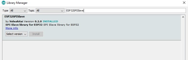
Open Arduino IDE and click on Sketch > Library > Manage Libraries.
When you click on the manage libraries option, you will get this window. In this window write ‘ESP32SPISlave‘ in the search bar and press enter.
Select the highlighted library and click on install.
Now copy the following Arduino sketch and upload it to ESP32 slave. The following code will read SPI data in blocking mode from a master. Based on data received from a controller, it will turn on and off onboard LED.
#include <ESP32SPISlave.h>

ESP32SPISlave slave;

static constexpr uint32_t BUFFER_SIZE {32};
uint8_t spi_slave_tx_buf[BUFFER_SIZE];
uint8_t spi_slave_rx_buf[BUFFER_SIZE];

#define LED 2
void setup() {
    Serial.begin(115200);
    delay(2000);
    pinMode(LED, OUTPUT);
    // begin() after setting
    // HSPI = CS: 15, CLK: 14, MOSI: 13, MISO: 12 -> default
    // VSPI = CS:  5, CLK: 18, MOSI: 23, MISO: 19
    slave.setDataMode(SPI_MODE0);
    slave.begin();
    // slave.begin(VSPI);   // you can use VSPI like this

    // clear buffers
    memset(spi_slave_tx_buf, 0, BUFFER_SIZE);
    memset(spi_slave_rx_buf, 0, BUFFER_SIZE);
}

void loop() {
    // block until the transaction comes from master
    slave.wait(spi_slave_rx_buf, spi_slave_tx_buf, BUFFER_SIZE);

    // if transaction has completed from master,
    // available() returns size of results of transaction,
    // and buffer is automatically updated
    char data;
    while (slave.available()) {
        // show received data
         Serial.print("Command Received: ");
         Serial.println(spi_slave_rx_buf[0]);
         data = spi_slave_rx_buf[0];
         slave.pop();
    }
    if(data == 1 )
    {
        Serial.println("Setting LED active HIGH ");
        digitalWrite(LED, HIGH);
    }
    else if(data == 0 )
    {
        Serial.println("Setting LED active LOW ");
        digitalWrite(LED, LOW);
    }
     Serial.println("");
}
How does Code Works?
First, include the header file of the ESP32 SPI peripheral or slave library.
#include <ESP32SPISlave.h>
Create an object of ESP32SPISlave class with the name of slave.
ESP32SPISlave slave;Define buffers to store data received on the MOSI pin of ESP32 SPI slave.
static constexpr uint32_t BUFFER_SIZE {32};
uint8_t spi_slave_tx_buf[BUFFER_SIZE];
uint8_t spi_slave_rx_buf[BUFFER_SIZE];
Define a name for onboard LED with #define preprocessor directive. We will use this name to configure and control the onboard LED of ESP32.
#define LED 2
Initialize serial communication with a baud rate of 115200. We will use it to print data on the serial monitor that HSPI slave will receive.
Serial.begin(115200);
Configure onboard LED of ESP32 as a digital output pin which is connected with GPIO2.
pinMode(LED, OUTPUT);
Set the data mode on slave object.
slave.setDataMode(SPI_MODE0); To initialize and start HSPI, call the begin() method on hspi object. It will initialize and make the HSPI bus in salve mode ready to use on default pins.
slave.begin();Clear the buffers and initialize them to zero.
memset(spi_slave_tx_buf, 0, BUFFER_SIZE);
memset(spi_slave_rx_buf, 0, BUFFER_SIZE);
Inside for loop, wait in blocking state until the data transaction comes from ESP32 master.
slave.wait(spi_slave_rx_buf, spi_slave_tx_buf, BUFFER_SIZE); If the transaction has been completed from the master, available() returns size of results of transaction, and a buffer is automatically updated. After that, send the received byte to the serial monitor for display. Additionally, save this byte in a data variable.
 char data;
 while (slave.available())
{
// show received data
Serial.print("Command Received: ");
Serial.println(spi_slave_rx_buf[0]);
data = spi_slave_rx_buf[0];
 slave.pop();
}
This if statement block checks if the data received is ‘1’, it will turn on the LED, and if it is ‘0’, it will turn off the LED. Also, it will print the LED status on the serial monitor.
if(data == 1 )
 {
Serial.println("Setting LED active HIGH ");
digitalWrite(LED, HIGH);
 }
 else if(data == 0 )
{
Serial.println("Setting LED active LOW ");
digitalWrite(LED, LOW);
}
After uploading Arduino sketches to both ESP32 boards, open the serial monitor of a slave device, you will get these messages on the serial monitor:
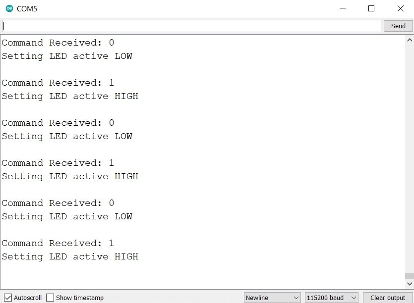
You will also see that the onboard LED of ESP32 slave will turn on and off with a delay of one second.
Video demo:
You may also like to read:
- ESP32 I2C Communication Set Pins, Multiple Devices Interfaces and Change Pins
- ESP32 UART Communication Explained with Example
- ESP32 MQTT Publish Subscribe DHT22 Readings with Arduino IDE
- ESP32 MQTT Publish Subscribe with Arduino IDE – Control Outputs
- ESP32 Web Server with SPIFFS (SPI Flash File System)
- Upload Files to ESP32 SPIFFS FileSystem with VS Code and PlatformIO IDE
- Install ESP32 Filesystem Uploader in Arduino IDE – SPIFFS
Other SPI tutorials:
May I suggest a correction of a typo in the table of section “ESP32 SPI Pins” where VSPI default CS/SS pin is 5 and not 15
Hi Richard,
Thanks for pointing a typo. We have fixed it.
Hello,
Thank you for the tutorial.
Hello,
Thank you for the tutorial.
I would appreciate your help. I am having an issue when I trying to compile the ESP32 SPI Slave Sketch:
ESP32SPISlave.h:48:28: error: ‘SOC_SPI_MAXIMUM_BUFFER_SIZE’ was not declared in this scope .max_transfer_sz = SOC_SPI_MAXIMUM_BUFFER_SIZE,
I tought it was an error associated to incompatibility between ESP32SPISLAVE library and my version of Arduino IDE (1.8.10). So, I download Arduino IDE 2.0.3 but the error still continues.
I will be waiting for your response.
Thanks.
How did you install slave library?
I didn’t need to install slave library, my library manager showed me it was already installed and it is the same version that you showed.
Hello Microcontrollers Lab and AnaMariaR. Thanks for the tutorial.
I have been trying to replicate the codes and I get the same error as AnaMariaR:
ESP32SPISlave.h:48:28: error: ‘SOC_SPI_MAXIMUM_BUFFER_SIZE’ was not declared in this scope .max_transfer_sz = SOC_SPI_MAXIMUM_BUFFER_SIZE,
Could you give me any advice to solve the problem? I would appreciate it a lot.
hello,
I’ve faced with same problem. Is there any solution?
Hello,
I also have the same problem.
I had installed the slave library as described via the administration
#include
ESP32SPISlave slave;
#define LED_PIN 2
static constexpr uint32_t BUFFER_SIZE = 8;
uint8_t tx_buf[BUFFER_SIZE] = {0};
uint8_t rx_buf[BUFFER_SIZE] = {0};
// — AQUÍ ESTÁ LA FUNCIÓN SETUP() —
void setup() {
Serial.begin(115200);
pinMode(LED_PIN, OUTPUT);
slave.setDataMode(SPI_MODE0);
slave.begin(VSPI);// o usa slave.begin(); si tienes otra configuración para los pines SPI
slave.queue(tx_buf, rx_buf, BUFFER_SIZE);
}
// — Y AQUÍ ESTÁ LA FUNCIÓN LOOP() —
void loop() {
slave.wait();
if (rx_buf[0] == 1) {
digitalWrite(LED_PIN, HIGH);
} else if (rx_buf[0] == 0) {
digitalWrite(LED_PIN, LOW);
}
memset(rx_buf, 0, BUFFER_SIZE);
slave.queue(tx_buf, rx_buf, BUFFER_SIZE);
}
Hi, thank you for the tutorial
One question, which are the pins that are finally used to interconnect the two ESP32? Because I used the default pins and they do not correspond to the ones I see in last picture and also I do not receive anything
#define HSPI_MISO 12
#define HSPI_MOSI 13
#define HSPI_SCLK 14
#define HSPI_SS 15
I have used the above pins, sometimes it gets confusing to understand, it’s better to declare pins. I also faced some issue regarding pins assignment so went with above approach. Alternatively, if you want to know which pins has been used, print the pin variables defined in code
Awesome tutorial, very informative! Thanks for taking the time to do this.
Nice! is it possible to permanently enable the slave?
how can I change rx and tx buffer sizes? There are uint8_t and I nedd uint16_t, I tried but it gave me errors
Were you able to get this to work with uint16_t?