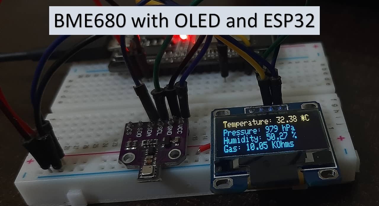
In this tutorial, we will learn to interface the BME680 sensor with ESP32 using Arduino IDE. The BME680 environmental sensor, which is used to measure ambient temperature, barometric pressure, relative humidity, and gas (VOC) or Indoor air quality (IAQ). We will learn how to interface it with ESP32 using Arduino core programming. For demonstration, firstly, we will a simple Arduino IDE code for reading the BME680 sensor data and displaying it on the serial monitor of Arduino IDE. Furthermore, we will also see an example to display BME680 sensor readings on an OLED display.
Prerequisites
Before we start this lesson, make sure you are familiar with and have the latest version of the Arduino IDE installed. Also, ensure that you have the ESP32 add-on installed in the Arduino IDE.
Install ESP32 add-on in Arduino IDE
BME680 Introduction
BME680 is a four-in-one power-driven sensor, which has integrated temperature, pressure, humidity, and gas detection sensors. It runs on an operating voltage of 1.8-3.8V and communicates with other microcontrollers through the I2C and SPI protocols. This sensor is used in areas such as tracking the quality of air, humidity indicators, weather trends, home automation, controlling, and GPS enhancements.
Operating Range and Accuracy
Some key features of BME680 include:
- Temperature measurement: measures the ambient temperature with an accuracy of ±1.0°C and an operating range of -40 to 85 ºC.
- Relative Humidity measurement: measures relative humidity with a fast response rate and an accuracy of ±3% and an operating range of 0-100%.
- Pressure measurement: measures barometric pressure with ±1 hPa absolute accuracy and altitude with an accuracy of ±1 meter. The operating range of pressure ranges from 300-1100 hPa.
| Accuracy | Operating Range | |
|---|---|---|
| Temperature | ±1.0°C | -40 to 85 ºC |
| Humidity | ±3% | 0-100% |
| Pressure | ±1 hPa | 300-1100 hPa |
- Gas measurement: detects a wide range of gases including volatile organic compounds (VOCs) thus determining the indoor air quality.
- Due to its compact size and low-power operation, it is suitable for mobile applications, smartwatches, and navigation systems.
As compared to BME280, BME680 is a unique and updated sensor in the sense that it contains a small-sized MOX (metal oxide) sensor.
Gas Sensor
BME680 sensor can determine the number of pollutants/VOCs in the environment such as carbon monoxide, Ethane, Isoprene /2-methyl-1,3 Butadiene, Acetone, and Ethanol. The VOCs are detected by the adsorption of oxygen molecules onto the metal oxide layer. Its actual detection is done by the principle of changing the resistance of the MOX sensor. Whenever the MOX gets in contact with a pollutant in the air, the resistance of the sensor changes with the concentration of the pollutants present. This means that the higher number of pollutants in the air leads to significantly lower resistance of the sensor. Likewise, with the lower concentration of VOCs in the air, the resistance of the sensor is significantly higher.
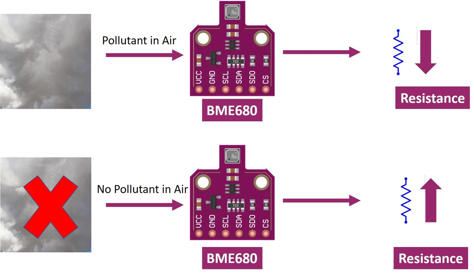
Note: The BME680 gas sensor is not a CO2 or ethanol measurement sensor. It gets the relative idea of CO2 from VOC in the air But we can not use it for direct measurement of CO2.
Like all other gas sensors, BME680 also gives variable results each time. To ensure greater accuracy, we have to calibrate it against a known source and then plot its curve. As the sensitivity levels are not constant during the initial use of the sensor, it is initially recommended to run it for forty-eight hours which can later be tuned down to thirty minutes before each use.
BME680 Modules
Several types of BME680 sensors with different sizes and numbers of terminals are available in the market. But all modules provide data through SPI and I2C interfaces and we can use the same Arduino sketch to get sensor readings. Some of them are shown below:
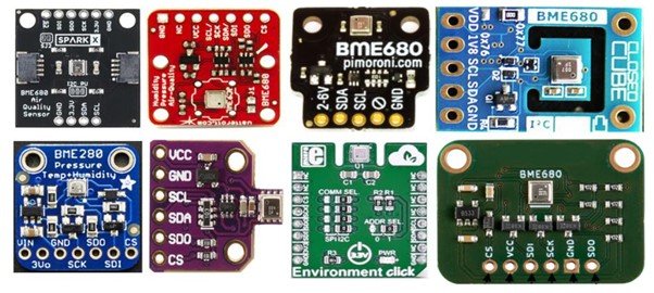
You can choose the module according to your convenience and the type of microcontroller you want to connect it with. In this article, we will use the BME680 sensor with 6 terminals, which is shown below. It has 4 SPI and two I2C terminals.
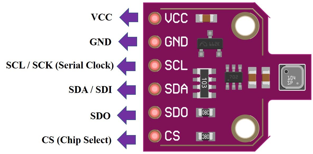
Pinout Diagram
The following figure shows the pinout of BME680 sensor:
| Pin Name | Description |
|---|---|
| VCC | This pin powers up the sensor. |
| GND | This is the common ground pin for power and logic. |
| SCL | When using I2C protocol this pin acts as SCL or serial clock pin and when using SPI protocol this pin acts as SCK or the serial pin for SPI. It is the input to the chip. |
| SDA | When using I2C protocol this pin acts as SDA or Serial Data pin and when using SPI protocol this pin acts as SDI or Serial Data In also known as MOSI (‘Master out Slave in’). This is used as the I2C/SPI input to the sensor. |
| SDO | This is the SDO (Slave data out) /MISO (Master in slave out) pin for SPI communication. This pin is used as the SPI output from the sensor. |
| CS | This is the Chip Select pin used in SPI communication. Acts as an input to the sensor. |
BME680 I2C and SPI Interface
In this section, we will see how to interface the BME680 sensor module with ESP32. As discussed earlier, the BME680 offers two interfaces such as I2C and SPI. We can use either SPI or I2C interface to connect a sensor with the ESP32. We will show the connections for both scenarios in the next section.
I2C Interface with ESP32
If you want to interface the BME680 sensor with ESP32 using the I2C interface, you should make the connections of the ESP32 board according to these SCL and SDA pins.
| BME680 | ESP32 |
|---|---|
| VCC | VCC=3.3V |
| GND | GND |
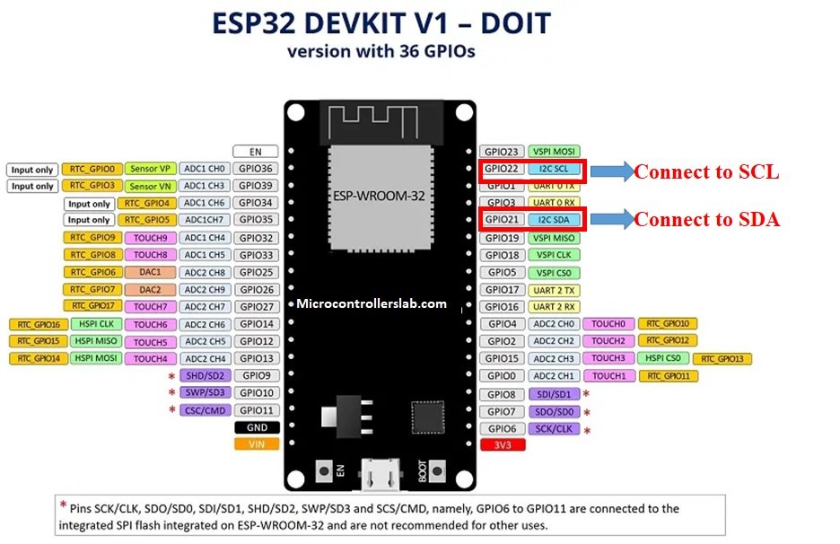
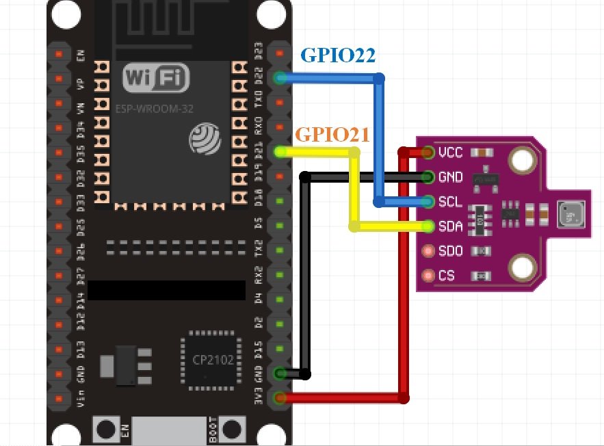
| SCL | GPIO22 |
| SDA | GPIO21 |
Connect the VCC pin of ESP32 with the 3.3V VCC pin of the module to power up. Both grounds of the two devices will be connected in common. The SCL pin of BME680 will be connected with the default SCL pin of ESP32. Likewise, the SDA pin will be connected with the default SDA pin of ESP32.
Note: If we use other GPIO pins of ESP32 for I2C communication, we can define other pins inside our Arduino sketch. We don’t have to use default I2C pins.
ESP32 I2C Pins
The I2C pins stated above are set in default. If we want to change the GPIO pins we have to set them in code. The diagrams below show the pinout for the ESP32.
More information on ESP32 pins is available here:
SPI Interface with ESP32
If you want to interface the BME680 sensor with ESP32 using the SPI interface, you should make the connections of ESP32 with the sensor according to these MOSI, MISO, and SCK pins. Because SPI protocol uses MOSI/SDI, MISO/SDO, and SCK pins.
| BME680 | ESP32 |
|---|---|
| VCC | VCC=3.3V |
| GND | GND |
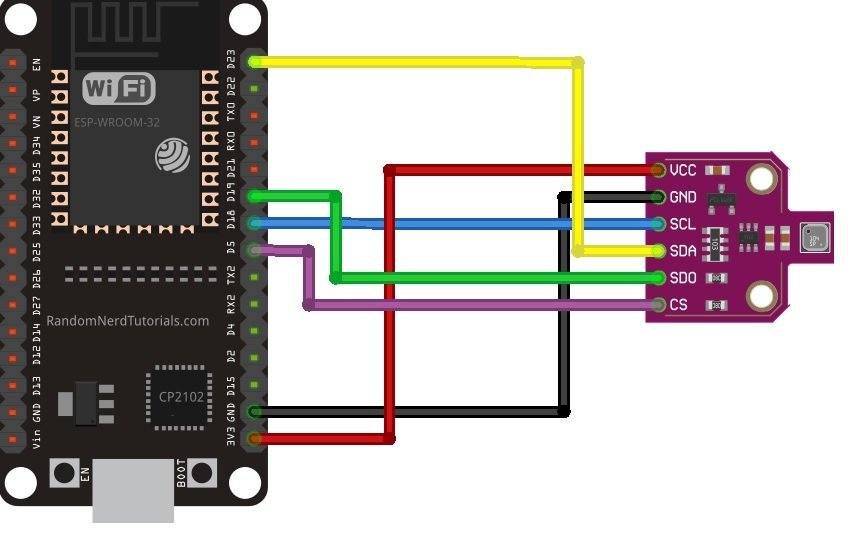
| SCL (SCK for SPI) | GPIO18 |
| SDA (SDI / MOSI for SPI) | GPIO23 |
| SDO / MISO | GPIO19 |
| CS | GPIO5 |
The VCC pin will be connected with the 3.3V from the ESP32 module to power up. Both the grounds of the two devices will be connected in common. The SCL pin of BME680 will be connected with the default SCK/CLK pin of ESP32. Likewise, the SDA pin will be connected with the default MOSI pin of ESP32. The SDO pin will be connected with the default MISO pin of ESP32 and the CS pin of the sensor will also be connected with the default CS pin of ESP32.
Note: The above table lists the default SPI pins of ESP32. But if you want to use any other pins, you need to define them inside Arduino sketch
As you can see, we will use the default I2C and default SPI pins of the ESP32 module to connect with the respective pins of the sensor. If you want to change the pins according to your preference that can be handled in the program code.
Which Interface to use?
So far we have discussed SPI and I2C interfaces of BME680 and learned to interface the sensor with ESP32 using both interfaces. But the question is which communication protocol should we use to get reading from BME680. As we have seen SPI requires four pins to communicate. On the contrary, I2C requires two pins. However, SPI is generally faster in speed as compared to I2C. Hence, it’s a tradeoff between speed and the number of pins. In short, it depends on your choice and application. We will use the I2C interface to get sensor readings with the default I2C pins of ESP32.
Required Hardware
We will need the following components to connect our ESP32 board with the BME680 sensor.
- ESP32
- BME680 Module
- Connecting Wires
- Breadboard
- 0.96 inch OLED Display
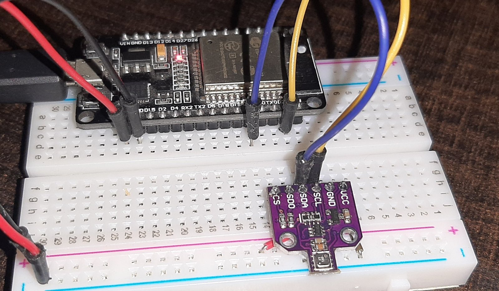
BME680 Connection Diagram with ESP32
Follow the schematic diagram given below to make connections of ESP32 with BME680 to interface through I2C communication.
Follow the schematic diagram given below to make connections of ESP32 with BME680 to interface through SPI communication:
Installing BME680 Library in Arduino
We will use Arduino IDE to program our ESP32 board with BME680. Make sure you have the ESP32 add-on already installed before proceeding further.
Arduino comes up with an in-built library for BME680 which we will initiate. To use the functions of the BME680 library we will also be installing the ‘Adafruit_Sensor Library.’ Follow the steps to ensure the successful installation of the libraries.
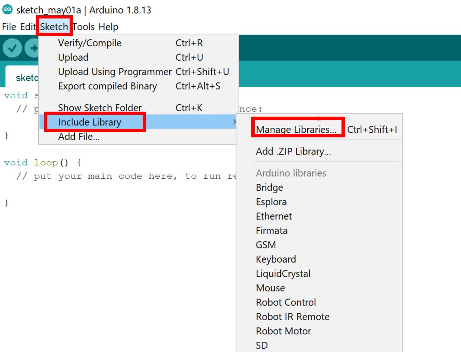
- In your Arduino IDE, click on Sketch > Include Library > Manage Library
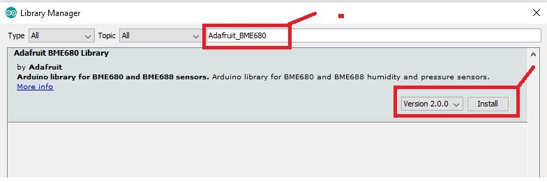
The Library manager window will open up. In the search bar type ‘adafruit bme680.’ Click on the install button as shown.
Now, we will install Adafruit_Sensor Library. Again, click on Sketch > Include Library > Manage Library.
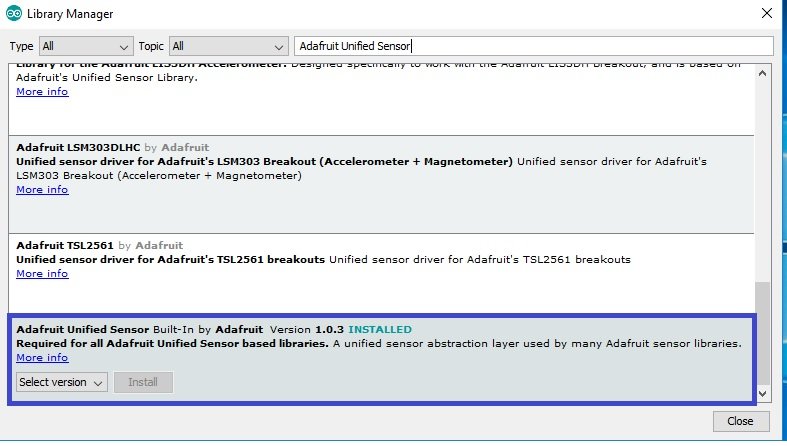
Type ‘adafruit unified sensor’in the search bar and install the library which is shown in the blue box below.
ESP32 Code: Display BME680 Values onSerial Monitor
Let us look at a sketch example to display temperature, pressure, humidity, and gas readings from the sensor module. After you have installed the libraries discussed above, restart your IDE and click on File > Examples > Adafruit BME680 Library > bme680async.
This will open up a new file titled bme680async which reads the sensor data and displays it on the serial monitor. You can view the code below:
#include <Wire.h>
#include <SPI.h>
#include <Adafruit_Sensor.h>
#include "Adafruit_BME680.h"

/*#define BME_SCK 18
#define BME_MISO 19
#define BME_MOSI 23
#define BME_CS 15*/

#define SEALEVELPRESSURE_HPA (1013.25)

Adafruit_BME680 bme; // I2C
//Adafruit_BME680 bme(BME_CS); // hardware SPI
//Adafruit_BME680 bme(BME_CS, BME_MOSI, BME_MISO, BME_SCK);

void setup() {
  Serial.begin(115200);
  while (!Serial);
  Serial.println(F("BME680 async test"));

  if (!bme.begin()) {
    Serial.println(F("Could not find a valid BME680 sensor, check wiring!"));
    while (1);
  }

  // Set up oversampling and filter initialization
  bme.setTemperatureOversampling(BME680_OS_8X);
  bme.setHumidityOversampling(BME680_OS_2X);
  bme.setPressureOversampling(BME680_OS_4X);
  bme.setIIRFilterSize(BME680_FILTER_SIZE_3);
  bme.setGasHeater(320, 150); // 320*C for 150 ms
}

void loop() {
  // Tell BME680 to begin measurement.
  unsigned long endTime = bme.beginReading();
  if (endTime == 0) {
    Serial.println(F("Failed to begin reading :("));
    return;
  }
  Serial.print(F("Reading started at "));
  Serial.print(millis());
  Serial.print(F(" and will finish at "));
  Serial.println(endTime);

  Serial.println(F("You can do other work during BME680 measurement."));
  delay(50); // This represents parallel work.
  // There's no need to delay() until millis() >= endTime: bme.endReading()
  // takes care of that. It's okay for parallel work to take longer than
  // BME680's measurement time.

  // Obtain measurement results from BME680. Note that this operation isn't
  // instantaneous even if milli() >= endTime due to I2C/SPI latency.
  if (!bme.endReading()) {
    Serial.println(F("Failed to complete reading :("));
    return;
  }
  Serial.print(F("Reading completed at "));
  Serial.println(millis());

  Serial.print(F("Temperature = "));
  Serial.print(bme.temperature);
  Serial.println(F(" *C"));

  Serial.print(F("Pressure = "));
  Serial.print(bme.pressure / 100.0);
  Serial.println(F(" hPa"));

  Serial.print(F("Humidity = "));
  Serial.print(bme.humidity);
  Serial.println(F(" %"));

  Serial.print(F("Gas = "));
  Serial.print(bme.gas_resistance / 1000.0);
  Serial.println(F(" KOhms"));

  Serial.print(F("Approx. Altitude = "));
  Serial.print(bme.readAltitude(SEALEVELPRESSURE_HPA));
  Serial.println(F(" m"));

  Serial.println();
  delay(2000);
}
How does the Code Work?
The code starts with including all the necessary libraries which are needed for the proper functionality of the code. Wire.h will allow us to communicate through the I2C protocol and SPI.h allows us to communicate through the SPI protocol. Both communication protocols are included. The Adafruit_Sensor and the Adafruit_BME680 libraries which we installed in Arduino IDE earlier are also included as they are necessary to interface with the sensor.
#include <Wire.h>
#include <SPI.h>
#include <Adafruit_Sensor.h>
#include "Adafruit_BME680.h"
This code uses using I2C protocol to communicate with ESP32 and BME680. If you want to use SPI protocol instead, just uncomment the following block of code which defines the default pins:
/*#define BME_SCK 18
#define BME_MISO 19
#define BME_MOSI 23
#define BME_CS 15*/
Next, the code defines the SEALEVELPRESSURE_HPA by creating a variable by the set name. It takes into account the sea level pressure of your current location and compares it with a given pressure to estimate the altitude. You have to pass your sea-level pressure in hPa according to your location. 1013.25 is the value that is set in default.
#define SEALEVELPRESSURE_HPA (1013.25)Then, it defines the Adafruit_BME680 object named ‘bme’ by setting it on the default I2C GPIO pins. If using SPI protocol instead, make sure to comment on this line and uncomment the lines which are initializing the SPI pins.
Adafruit_BME680 bme; // I2C
//Adafruit_BME680 bme(BME_CS); // hardware SPI
//Adafruit_BME680 bme(BME_CS, BME_MOSI, BME_MISO, BME_SCK);
The setup() function is created. This initiates the serial communication at a baud rate of 115200 by using the begin() function.
Serial.begin(115200);Then, the BME680 sensor gets initialized and in case of failure, an error message is printed on the serial monitor.
Serial.println(F("BME680 async test"));

  if (!bme.begin()) {
    Serial.println(F("Could not find a valid BME680 sensor, check wiring!"));
    while (1);
  }
The code then initializes some parameters, including oversampling, gas heater, and filters. It uses setTemperatureOversampling(), setHumidityOversampling(), and setPressureOversampling() to initialize the oversampling for temperature, humidity, and pressure, respectively. This is being done so that a better resolution of the data can be obtained. Inside these methods, a single default argument is being passed, which can be changed according to your preference.
All of these methods accept one of the following arguments. These indicate the different extents of oversampling which could be performed.
- BME680_OS_NONE: no reading
- BME680_OS_1X: default
- BME680_OS_2X: double oversampling
- BME680_OS_4X
- BME680_OS_8X
- ME680_OS_16X
The setIIRFilterSize() also takes in a single parameter which is the size of the filter. You can use any one of the following:
- BME680_FILTER_SIZE_0: no filter activated
- BME680_FILTER_SIZE_1
- BME680_FILTER_SIZE_3: this is the default size
- BME680_FILTER_SIZE_7
- BME680_FILTER_SIZE_15
- BME680_FILTER_SIZE_31
- BME680_FILTER_SIZE_63
- BME680_FILTER_SIZE_127
This internal infinite impulse response (IIR) filter is used to reduce the bandwidth of the sensor readings so that unnecessary changes caused by external disturbances could be significantly diminished. This is mainly used on temperature and pressure readings which fluctuate a lot and need low pass filtering.
The setGasHeater() configures a heater for gas measurement. It takes two parameters to initialize it. The first parameter is the target temperature for the heater which is set up as 32 degrees Celsius and the second parameter is the time duration set as 150ms.
These are the default values but you can change them by passing appropriate parameters. You should note that the target temperature of the heater is 200-400 degrees Celsius and it takes approximately 30ms to reach the appropriate temperature. So, all this should be taken into account while setting the parameters.
All of these five methods are being accessed through the bme object.
 // Set up oversampling and filter initialization
  bme.setTemperatureOversampling(BME680_OS_8X);
  bme.setHumidityOversampling(BME680_OS_2X);
  bme.setPressureOversampling(BME680_OS_4X);
  bme.setIIRFilterSize(BME680_FILTER_SIZE_3);
  bme.setGasHeater(320, 150); // 320*C for 150 ms
Inside the loop(), the code measures the sensor readings and displays them. The bme.beginReading() starts the reading process and prints the time when all the readings are acquired.
// Tell BME680 to begin measurement.
  unsigned long endTime = bme.beginReading();
  if (endTime == 0) {
    Serial.println(F("Failed to begin reading :("));
    return;
  }
  Serial.print(F("Reading started at "));
  Serial.print(millis());
  Serial.print(F(" and will finish at "));
  Serial.println(endTime);

  Serial.println(F("You can do other work during BME680 measurement."));
  delay(50); // This represents parallel work.
The bme.endReading() stops the reading process. It uses an if statement to print whether the sensor readings have all been read or not.
// There's no need to delay() until millis() >= endTime: bme.endReading()
  // takes care of that. It's okay for parallel work to take longer than
  // BME680's measurement time.

  // Obtain measurement results from BME680. Note that this operation isn't
  // instantaneous even if milli() >= endTime due to I2C/SPI latency.
  if (!bme.endReading()) {
    Serial.println(F("Failed to complete reading :("));
    return;
  }
The readings are printed on the serial monitor by using bme.temperature, bme.pressure, bme.humidity, and bme.gas_resistance. These measure ambient temperature, barometric pressure, relative humidity, and gas respectively. The units are also displayed.
Serial.print(F("Reading completed at "));
  Serial.println(millis());

  Serial.print(F("Temperature = "));
  Serial.print(bme.temperature);
  Serial.println(F(" *C"));

  Serial.print(F("Pressure = "));
  Serial.print(bme.pressure / 100.0);
  Serial.println(F(" hPa"));

  Serial.print(F("Humidity = "));
  Serial.print(bme.humidity);
  Serial.println(F(" %"));

  Serial.print(F("Gas = "));
  Serial.print(bme.gas_resistance / 1000.0);
  Serial.println(F(" KOhms"));

  Serial.print(F("Approx. Altitude = "));
  Serial.print(bme.readAltitude(SEALEVELPRESSURE_HPA));
  Serial.println(F(" m"));

  Serial.println();
  delay(2000);
Demonstration
In Arduino IDE, click Tools > Board and select ESP32.

Now, click Tools > Port and choose the port which you are using. Now, upload the code by clicking on the upload button.

After you have uploaded the following code on your ESP32 development board, press the ENABLE button as follows:

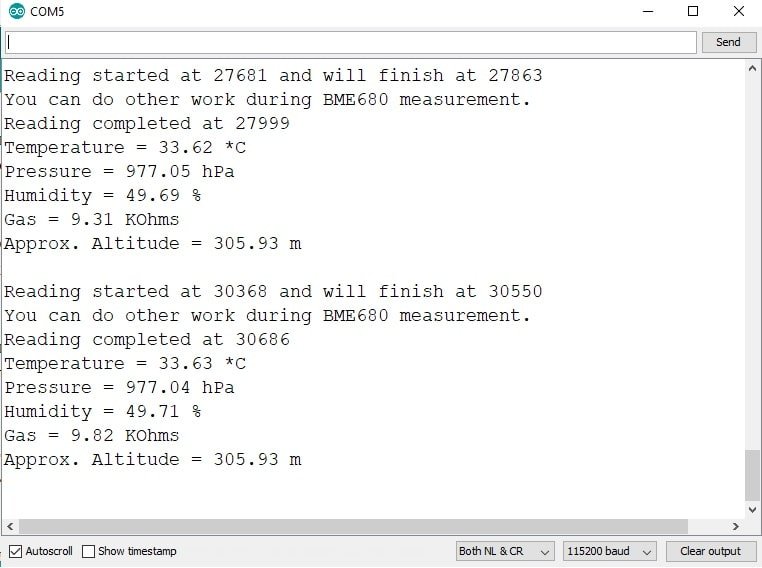
You will see the serial monitor displaying all the BME680 sensor readings such as Gas, Pressure, Temperature, and Humidity as shown below:
Displaying BME680 Sensor values on OLED Display with Arduino IDE
In this section, we will see how to display Gas, Pressure, Temperature, and Humidity values on a 0.96 SSD1306 OLED display using ESP32 and Arduino IDE.
Installing SSD1306 OLED Library in Arduino IDE
To use the OLED display in our project, we have to install the Adafruit SSD 1306 library in Arduino IDE. Follow the steps below to successfully install it.
Open Arduino IDE and click on Sketch > Library > Manage Libraries
The following window will open up.

Type ‘SSD1306’ in the search tab and install the Adafruit SSD1306 OLED library.

You can read this in-depth guide on OLED interfacing with ESP32:
Connection Diagram– OLED with ESP32 and BME680
The table below shows the terminals of the three devices which would be connected together.
| OLED Display | ESP32 | BME680 |
|---|---|---|
| VCC | VCC=3.3V | VCC |
| GND | GND | GND |
| SCL | GPIO22 | SCL |
| SDA | GPIO21 | SDA |
Assemble the circuit as shown in the schematic diagram below:

As you can see above, we have connected all the VCC terminals with a 3.3V power supply. The SCL terminals are connected with GPIO22 and the SDA terminals are connected with GPIO21. The grounds are also common.
ESP32 Code: Displaying BME680 readings on OLED Display
Copy the following code to your Arduino IDE and upload it to the ESP32 after assembling the above circuit diagram.
/***************************************************************************
  This is a library for the BME680 gas, humidity, temperature & pressure sensor

  Designed specifically to work with the Adafruit BME680 Breakout
  ----> http://www.adafruit.com/products/3660

  These sensors use I2C or SPI to communicate, 2 or 4 pins are required
  to interface.

  Adafruit invests time and resources providing this open source code,
  please support Adafruit and open-source hardware by purchasing products
  from Adafruit!

  Written by Limor Fried & Kevin Townsend for Adafruit Industries.
  BSD license, all text above must be included in any redistribution
 ***************************************************************************/

#include <Wire.h>
#include <SPI.h>
#include <Adafruit_Sensor.h>
#include "Adafruit_BME680.h"
#include <Adafruit_GFX.h>
#include <Adafruit_SSD1306.h>

#define BME_SCK 13
#define BME_MISO 12
#define BME_MOSI 11
#define BME_CS 10

#define SEALEVELPRESSURE_HPA (1013.25)

Adafruit_BME680 bme; // I2C
//Adafruit_BME680 bme(BME_CS); // hardware SPI
//Adafruit_BME680 bme(BME_CS, BME_MOSI, BME_MISO,  BME_SCK);

Adafruit_SSD1306 display = Adafruit_SSD1306(128, 32, &Wire);

void setup() {
  Serial.begin(9600);
  Serial.println(F("BME680 test"));

  // by default, we'll generate the high voltage from the 3.3v line internally! (neat!)
  display.begin(SSD1306_SWITCHCAPVCC, 0x3C);  // initialize with the I2C addr 0x3C (for the 128x32)
  // init done
  display.display();
  delay(100);
  display.clearDisplay();
  display.display();
  display.setTextSize(1);
  display.setTextColor(WHITE);

  if (!bme.begin()) {
    Serial.println("Could not find a valid BME680 sensor, check wiring!");
    while (1);
  }

  // Set up oversampling and filter initialization
  bme.setTemperatureOversampling(BME680_OS_8X);
  bme.setHumidityOversampling(BME680_OS_2X);
  bme.setPressureOversampling(BME680_OS_4X);
  bme.setIIRFilterSize(BME680_FILTER_SIZE_3);
  bme.setGasHeater(320, 150); // 320*C for 150 ms
}

void loop() {
  display.setCursor(0,0);
  display.clearDisplay();

  if (! bme.performReading()) {
    Serial.println("Failed to perform reading :(");
    return;
  }
  Serial.print("Temperature = "); Serial.print(bme.temperature); Serial.println(" *C");
  display.print("Temperature: "); display.print(bme.temperature); display.println(" *C");

  Serial.print("Pressure = "); Serial.print(bme.pressure / 100.0); Serial.println(" hPa");
  display.print("Pressure: "); display.print(bme.pressure / 100); display.println(" hPa");

  Serial.print("Humidity = "); Serial.print(bme.humidity); Serial.println(" %");
  display.print("Humidity: "); display.print(bme.humidity); display.println(" %");

  Serial.print("Gas = "); Serial.print(bme.gas_resistance / 1000.0); Serial.println(" KOhms");
  display.print("Gas: "); display.print(bme.gas_resistance / 1000.0); display.println(" KOhms");

  Serial.println();
  display.display();
  delay(2000);
}
How Code Works?
The maximum portion of the code is the same as we have discussed earlier except for the OLED display part. Therefore, we will only explain the OLED display part here.
Include Libraries
We will first include all the required libraries for the BME680 sensor as well as the OLED display which we just installed before.
#include <SPI.h>
#include <Adafruit_Sensor.h>
#include "Adafruit_BME680.h"
#include <Adafruit_GFX.h>
#include <Adafruit_SSD1306.h>
Now, we will create another object named ‘display’ which will be handling the OLED display. Also, define the size of OLED display by passing arguments to Adafruit_SSD1306() function.
Adafruit_SSD1306 display = Adafruit_SSD1306(128, 32, &Wire);This block of code initializes the OLED display.
// by default, we'll generate the high voltage from the 3.3v line internally! (neat!)
  display.begin(SSD1306_SWITCHCAPVCC, 0x3C);  // initialize with the I2C addr 0x3C (for the 128x32)
We have set the font size as default which is 1. Whenever we increase the size by +1, the pixel resolution of the text increases by 10 in height. Next, we will control the color of the text by using the setTextColor() function and passing WHITE as an argument. If we have a dark background, we will display our text in white and if we have a bright background then we will display the text in black. We do not want to rotate the text, so we are passing 0 as the parameter inside the setRotation() function. The parameter can take in any value from 0,1,2,3 where 0 denotes a rotation of 0 degrees, 1 denotes a rotation of 90 degrees, 2 denotes a rotation of 180 degrees and 3 denotes a rotation of 270 degrees.
// init done
  display.display();
  delay(100);
  display.clearDisplay();
  display.display();
  display.setTextSize(1);
  display.setTextColor(WHITE);
The loop() obtains the readings from the sensors and prints them on the OLED display. We will first create events for the accelerometer (a), gyroscope (g), and temperature (t) and get their new sensor readings. The clearDisplay() function wipes off the previous readings from the display after each loop() so that new ones can be printed.
display.setCursor(0,0);We will use the setCursor() function to denote the x and the y-axis position from where the text should start. We have passed (0,0) as the parameter hence the text starts from the upper left corner.
display.setCursor(0, 0);Now let’s display the temperature, pressure, humidity, and gas values on the serial monitor and OLED one by one. This block of code displays BME680 sensor values on the OLED and updates the value every 2 seconds.
if (! bme.performReading()) {
    Serial.println("Failed to perform reading :(");
    return;
  }
  Serial.print("Temperature = "); Serial.print(bme.temperature); Serial.println(" *C");
  display.print("Temperature: "); display.print(bme.temperature); display.println(" *C");

  Serial.print("Pressure = "); Serial.print(bme.pressure / 100.0); Serial.println(" hPa");
  display.print("Pressure: "); display.print(bme.pressure / 100); display.println(" hPa");

  Serial.print("Humidity = "); Serial.print(bme.humidity); Serial.println(" %");
  display.print("Humidity: "); display.print(bme.humidity); display.println(" %");

  Serial.print("Gas = "); Serial.print(bme.gas_resistance / 1000.0); Serial.println(" KOhms");
  display.print("Gas: "); display.print(bme.gas_resistance / 1000.0); display.println(" KOhms");

  Serial.println();
  display.display();
  delay(2000);
Demonstration
To see the demonstration of the above code, upload the code to Arduino. But, before uploading code, make sure to select the ESP32 board from Tools > Board and also select the correct COM port to which the ESP32 board is connected from Tools > Port.
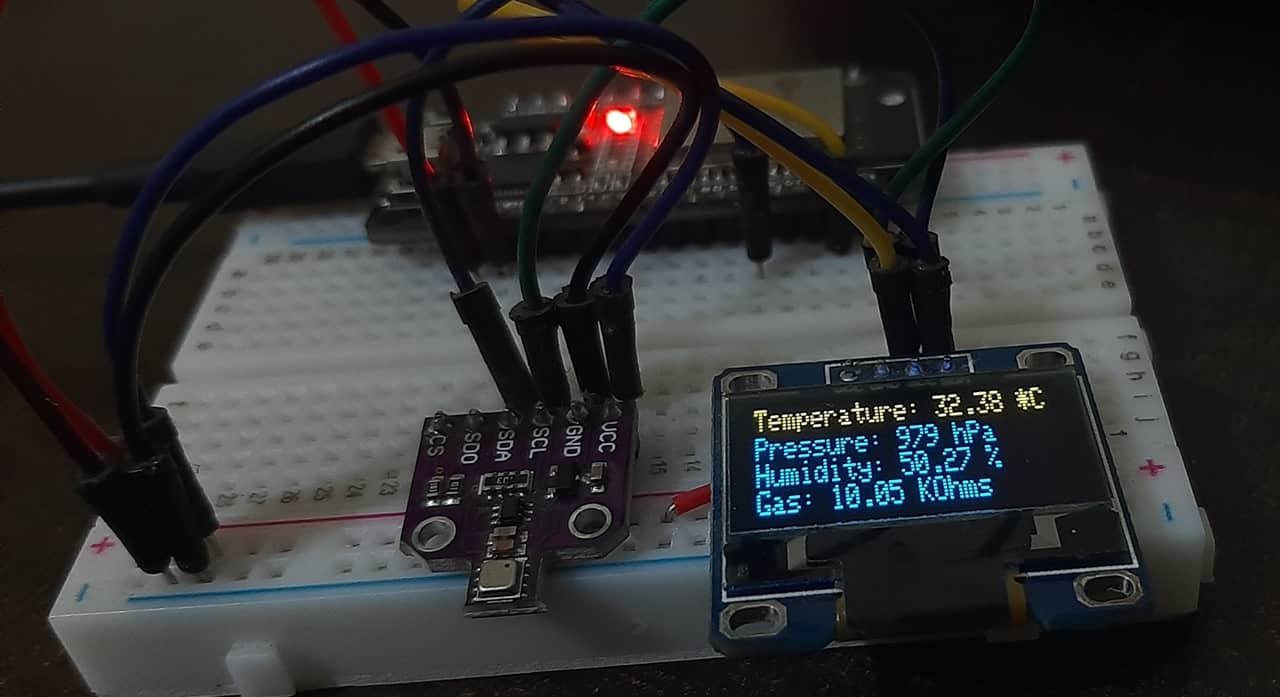
Once the code is uploaded to ESP32, open the serial monitor of Arduino IDE and set the baud rate to 115200. Finally, we can see the BME680 readings on the Arduino serial monitor and on the OLED display as follows:
Video Demo:
If you found this tutorial useful, we have a similar guide for BME680 using MicroPython:
- MicroPython: BME680 with ESP32 and ESP8266
- MicroPython: BME680 Web Server with ESP32 and ESP8266
- OLED Display with ESP32 and ESP8266 in MicroPython
- BME680 Web Server with ESP32 ( Arduino IDE)
- ESP32/ESP8266 Thermostat Web Server – Control Output Based on Temperature Threshold
- ESP32 Server-Sent Events (SSE) Web Server (Arduino IDE)
Thank you for your very detailed article on the BME680. I have used the Bosch BSEC library with the BME680 to create a data logger, webserver and OLED display: https://github.com/Tech500/BME680-BSEC-Studies
Included on gitbub repository linked; are graphs of testing acetone exposed to the BME680 on a “Q-Tip.”
Hi William,
Thanks for sharing, it looks great.