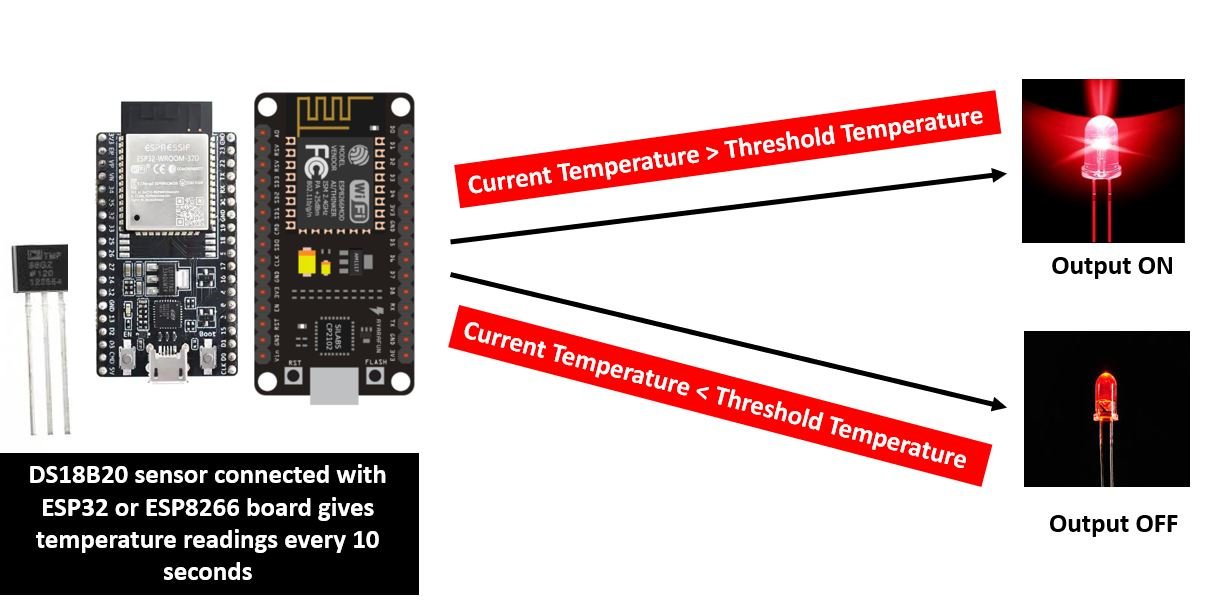
In this user guide, we will learn how to create an ESP32 and ESP8266 thermostat web server with a temperature threshold input. The web server will control ESP boards output ON/OFF based on a certain temperature threshold set by the user from a web page. The web server will allow the user to change the threshold value via an input field. Users can also enable and disable this trigger system. When the current temperature goes above the threshold set by the user, the ESP output will be turned ON. similarly, when the current temperature will go below the threshold set by the user, the ESP output will be turned OFF. Through this feature, the user will be able to control the ESP32/8266 output through the thermostat web server.
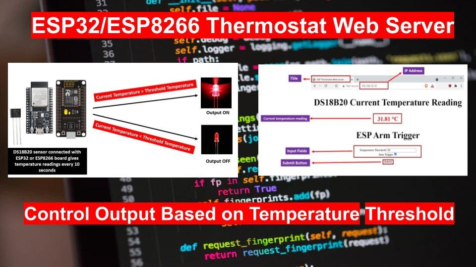
This article will be useful for readers who want to control an output e.g., relay, buzzer, etc. when the temperature goes above or below a certain threshold value. For this article, we will keep it simple and control an LED connected to an output GPIO of our ESP32/8266 module through temperature thresholds in Arduino IDE.
We will connect the DS18B20 temperature sensor with our ESP32 board to access the current temperature readings. One of the advantages of using this sensor is that we will only require a single pin of our ESP board to transfer data. Therefore, it is extremely convenient to use it with the microcontroller as we can measure multiple temperatures by using the least number of pins on our development board. You can use any other temperature sensor as well including LM35, thermistor, DS18S20, DHT11/DHT22, and various others.
Recommended Reading: Single and Multiple DS18B20 with ESP32: Display Readings on OLED
Recommended Components
The following components are used in this project or are helpful for building it with the ESP32.
| Component | How it’s used in this project | Buy on Amazon |
|---|---|---|
| ESP32 Development Board (DevKit V1) | The main board that runs the project firmware. | Check Price |
| ESP8266 NodeMCU (ESP-12E) | An alternative Wi-Fi board; this tutorial works on the ESP8266 NodeMCU as well. | Check Price |
| Micro USB Cable | Connects the board to your computer to upload code and power it. | Check Price |
| Breadboard | Holds the board and components together while you wire up the project. | Check Price |
| Jumper Wires | Make the connections between the board and any external parts. | Check Price |
| DHT22 sensor | Measures temperature so the thermostat can compare it against your threshold. | Check Price |
| Relay module | Switches the heating/cooling output when the temperature crosses the threshold. | Check Price |
As an Amazon Associate we earn from qualifying purchases. Prices and availability are accurate as of the date/time indicated and are subject to change.
ESP32 and ESP8266 Thermostat Web Server Project Overview
We will build a web server that will allow us to set a temperature threshold and a checkbox to activate the trigger. We aim to turn an LED ON/OFF when the temperature goes over or under the threshold value respectively. The ESP32 module will be connected to a DS18B20 sensor which will display current temperature readings on the web server.
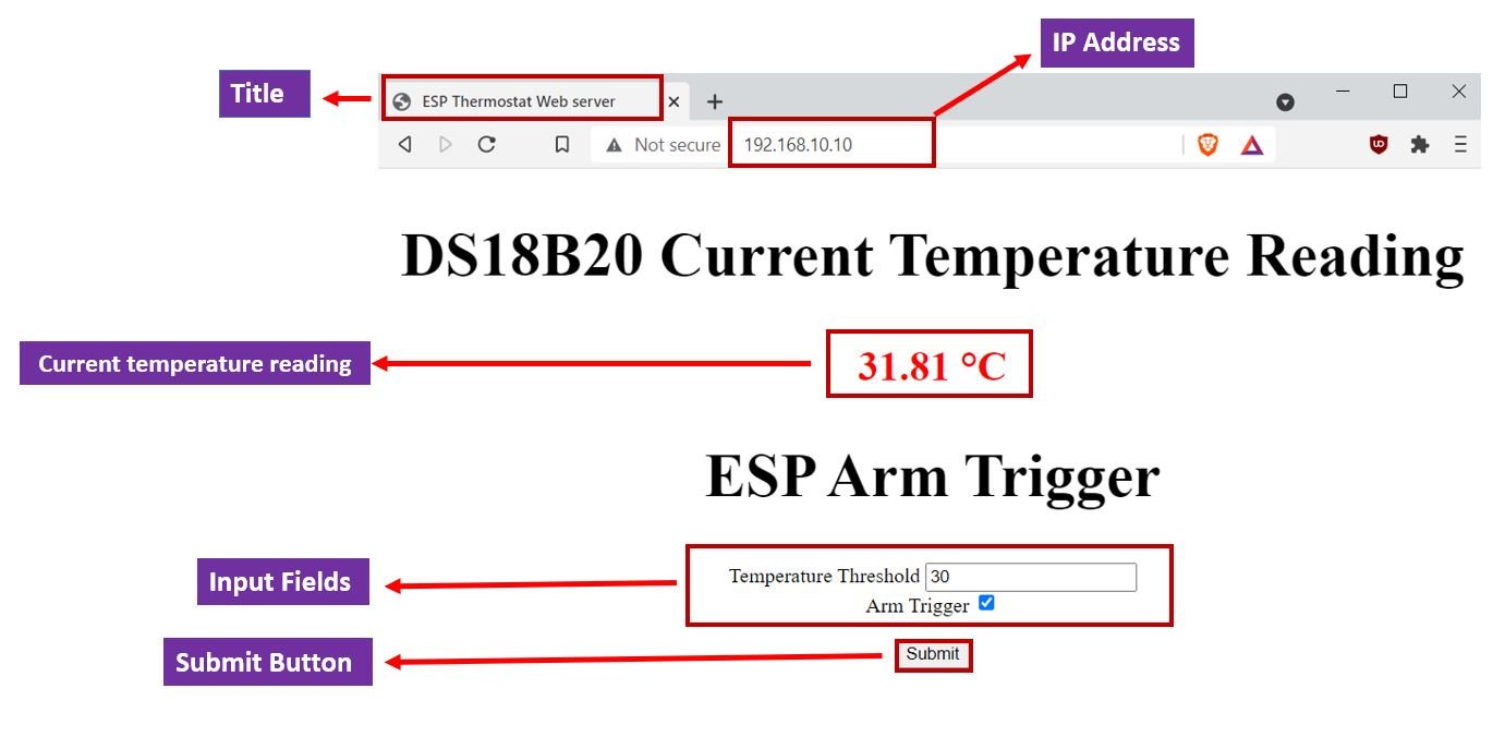
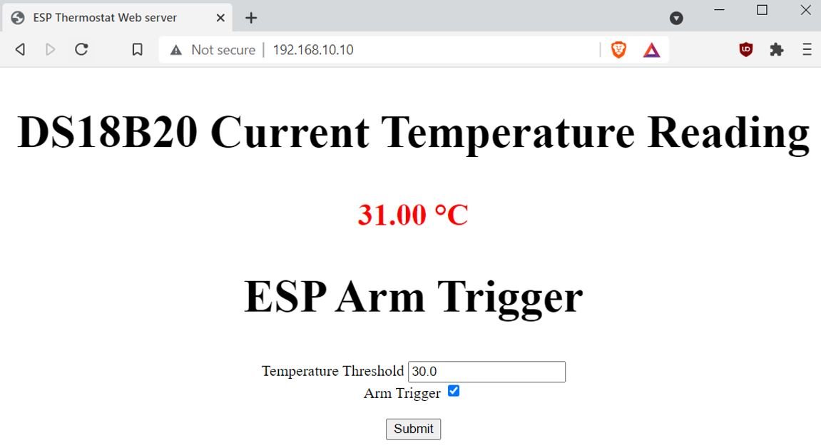
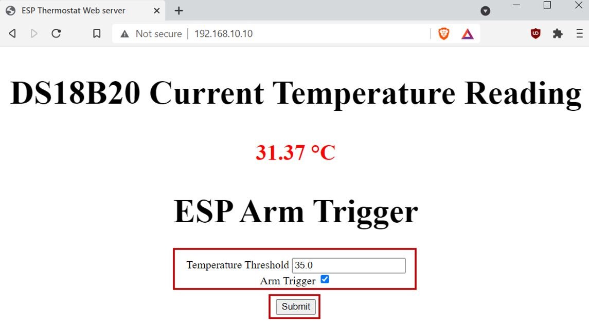
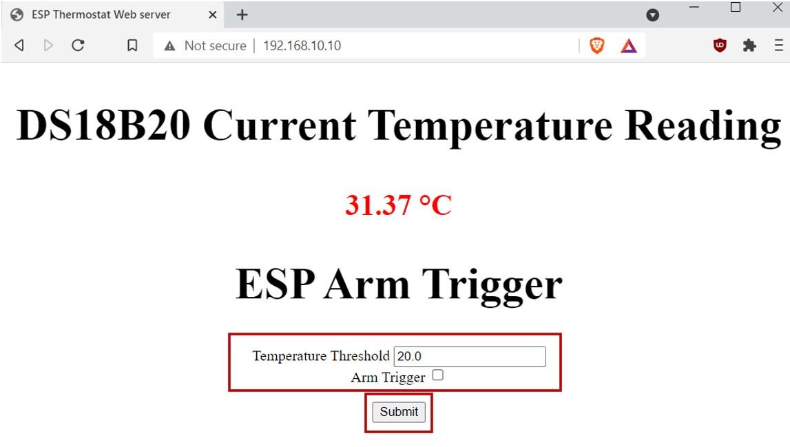
Inside the web page, there will heading ‘DS18B20 Current Temperature Reading’. The current temperature value in degrees Celsius will be displayed beneath it. Then there will be another heading called ‘ESP Arm Trigger. Underneath it, there will be an input field for the user to set the threshold temperature and a checkbox to enable the threshold trigger. Whenever the temperature value will go above or below this value, the LED will be controlled accordingly. The user can activate/deactivate the thermostat through a checkbox. After you click the submit button, the settings will then come in place.
We also have another dedicated ESP32 tutorial where we sent emails based on temperature threshold. You can view it by following the link. Send Email Alert Based on Temperature Threshold and Update Threshold value with ESP32 Web Server. In that article, the emails were sent using the ESP32 development board through an SMTP server whenever the current temperature went above/below the threshold value.
Required Components
For this project we will require the following components:
- ESP32/ESP8266 board
- DS18B20 temperature sensor
- LED
- 220-ohm resistor
- 4.7k ohm resistor
- Connecting wires
- Breadboard
ESP32/ESP8266 Thermostat Web Server Project Schematic Diagram
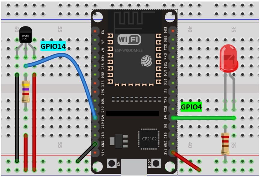
Follow the schematic diagram below, to connect the DS18B20 sensor and LED with your ESP32 module:
Follow the schematic diagram below, to connect the DS18B20 sensor and LED with your ESP8266 module:
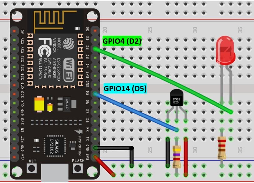
As you can see above, we have powered the sensor using the normal mode. The DS18B20 sensor has three terminals. The first terminal is grounded with the ESP board. The data line of the sensor, which is the middle terminal, is connected through GPIO14 through a pull-up resistor of 4.7k-ohm on one side and the other side from 3.3V. You can choose any other GPIO pin as well. The third terminal is powered by 3.3V from the ESP board. We can see that GPIO4 is connected with the anode pin of LED and the cathode pin is connected with the common ground through the 220-ohm resistor.
Setting up Arduino IDE
We will use Arduino IDE to program our ESP32/ESP8266 development board. Thus, you should have the latest version of Arduino IDE. Additionally, you also need to install the ESP32 and the ESP8266 plugin. If your IDE does not have the plugins installed you can visit the links below:
Installing ESP32 library in Arduino IDE and uploading code
Installing ESP8266 library in Arduino IDE
DS18B20 Libraries
To use the Dallas DS18B20 sensor we will have to install two libraries.
- OneWire library
- DallasTemperature library
Follow the steps below to successfully install them. We will use the Library Manager in our Arduino IDE to install the latest versions of the libraries. Open your Arduino IDE and go to Sketch > Include Libraries > Manage Libraries. Type each library name in the search bar and install them both.
Installing ESPAsyncWebServer Library and Async TCP/ ESP Async TCP Library
We will build the asynchronous web server with the help of the ESPAsycWebServer library.
We will need two libraries to build our web server.
- ESP32: ESPAsyncWebServer & AsyncTCP
- ESP8266: ESPAsyncwebServer & ESPAsyncTCP
The ESPAsyncWebServer library will help us in creating our web server easily. With this library, we will set up an asynchronous HTTP server. AsyncTCP (for ESP32 only) and ESPAsyncTCP (for ESP8266 only) library will also be incorporated as it a dependency for the ESPAsyncWebServer library. All of these libraries are not available in the Arduino library manager. Therefore, we will have to download and load them on our ESP32/ESP8266 board ourselves.
For ESP32 & ESP8266:
- To install the ESPAsyncWebServer library for free, click here to download. You will download the library as a .zip folder which you will extract and rename as ‘ESPAsyncWebServer.’ Then, transfer this folder to the installation library folder in your Arduino IDE.
For ESP32 Only:
- To install the Async TCP library for free, click here to download. You will download the library as a .zip folder which you will extract and rename as ‘AsyncTCP.’ Then, transfer this folder to the installation library folder in your Arduino IDE.
For ESP8266 Only:
- To install the ESPAsync TCP library for free, click here to download. You will download the library as a .zip folder which you will extract and rename as ‘ESPAsyncTCP.’ Then, transfer this folder to the installation library folder in your Arduino IDE.
Likewise, you can also go to Sketch > Include Library > Add .zip Library inside the IDE to add the libraries as well. After installation of the libraries, restart your IDE.
ESP32/ESP8266 Thermostat Web Server Code
Open your Arduino IDE and go to File > New to open a new file. Copy the code given below in that file. This code will work for both ESP32 and ESP8266 development boards. You just need to enter your network credentials.
#ifdef ESP32
  #include <WiFi.h>
  #include <AsyncTCP.h>
#else
  #include <ESP8266WiFi.h>
  #include <ESPAsyncTCP.h>
#endif
#include <ESPAsyncWebServer.h>
#include <Wire.h>
#include <OneWire.h>
#include <DallasTemperature.h>
const char* ssid = "Your_SSID"; //replace with your SSID
const char* password = "Your_Password"; //replace with your password
String input_field = "30.0";
String last_temperature;
String enable_trigger = "checked";
String input_field2 = "true";
const char index_html[] PROGMEM = R"rawliteral(
<!DOCTYPE HTML><html><head>
<title>ESP Thermostat Web server</title>
<meta name="viewport" content="width=device-width, initial-scale=1">
<style>
html {font-family: Times New Roman; display: inline-block; text-align: center;}
h2 {font-size: 3.0rem;}
h3 {font-size: 2.0rem; color: #FF0000;}
</style>
</head><body>
<h2>DS18B20 Current Temperature Reading</h2>
<h3>%TEMPERATURE% °C</h3>
<h2>ESP Arm Trigger</h2>
<form action="/get">
Temperature Threshold <input type="number" step="0.1" name="threshold_input" value="%THRESHOLD%" required><br>
Arm Trigger <input type="checkbox" name="enable_triggerInput" value="true" %ENABLE_TRIGGER_INPUT%><br><br>
<input type="submit" value="Submit">
</form>
</body></html>)rawliteral";
void notFound(AsyncWebServerRequest *request) {
request->send(404, "text/plain", "Not found");
}
AsyncWebServer server(80);
String processor(const String& var){
if(var == "TEMPERATURE"){
return last_temperature;
}
else if(var == "THRESHOLD"){
return input_field;
}
else if(var == "ENABLE_TRIGGER_INPUT"){
return enable_trigger;
}
return String();
}
bool triggerActive = false;
const char* input_paramter1 = "threshold_input";
const char* input_paramter2 = "enable_triggerInput";
unsigned long previousMillis = 0;
const long interval = 10000;
const int ESP_output = 4;
const int oneWireBus = 14;
OneWire oneWire(oneWireBus);
DallasTemperature sensors(&oneWire);
void setup() {
Serial.begin(115200);
WiFi.mode(WIFI_STA);
WiFi.begin(ssid, password);
if (WiFi.waitForConnectResult() != WL_CONNECTED) {
Serial.println("Connecting...");
return;
}
Serial.println();
Serial.print("IP Address: ");
Serial.println(WiFi.localIP());
pinMode(ESP_output, OUTPUT);
digitalWrite(ESP_output, LOW);
sensors.begin();
server.on("/", HTTP_GET, [](AsyncWebServerRequest *request){
request->send_P(200, "text/html", index_html, processor);
});
server.on("/get", HTTP_GET, [] (AsyncWebServerRequest *request) {
if (request->hasParam(input_paramter1)) {
input_field = request->getParam(input_paramter1)->value();
if (request->hasParam(input_paramter2)) {
input_field2 = request->getParam(input_paramter2)->value();
enable_trigger = "checked";
}
else {
input_field2 = "false";
enable_trigger = "";
}
}
Serial.println(input_field);
Serial.println(input_field2);
request->send(200, "text/html", "HTTP GET request sent to your ESP.<br><a href=\"/\">Return to Home Page</a>");
});
server.onNotFound(notFound);
server.begin();
}
void loop() {
unsigned long currentMillis = millis();
if (currentMillis - previousMillis >= interval) {
previousMillis = currentMillis;
sensors.requestTemperatures();
// Temperature in Celsius degrees
float temperature = sensors.getTempCByIndex(0);
Serial.print(temperature);
Serial.println(" °C");
last_temperature = String(temperature);
if(temperature > input_field.toFloat() && input_field2 == "true" && !triggerActive){
String message = String("Temperature above threshold. Current temperature: ") +
String(temperature) + String("C");
Serial.println(message);
triggerActive = true;
digitalWrite(ESP_output, HIGH);
}
else if((temperature < input_field.toFloat()) && input_field2 == "true" && triggerActive) {
String message = String("Temperature below threshold. Current temperature: ") +
String(temperature) + String(" C");
Serial.println(message);
triggerActive = false;
digitalWrite(ESP_output, LOW);
}
}
}How does the Code Work?
Including Libraries
Firstly, we will include all the necessary libraries which are required for this project. As this code is compatible with both ESP32 and ESP8266 thus both libraries (WiFi.h and ESP8266WiFi.h) are defined. This library will help in establishing the connection between our ESP module to a wireless network. We will also import the libraries which we installed previously, the ESPAsyncWebServer library, ESPAsyncTCP, AsyncTCP library, and the two libraries required for ds18b20 sensor functionality.
#ifdef ESP32
#include <WiFi.h>
#include <AsyncTCP.h>
#else
#include <ESP8266WiFi.h>
#include <ESPAsyncTCP.h>
#endif
#include <ESPAsyncWebServer.h>
#include <Wire.h>
#include <OneWire.h>
#include <DallasTemperature.h>Setting Network Credentials
Next, we will create two global variables, one for the SSID and the other for the password. These will hold our network credentials which will be used to connect to our wireless network. Replace both of them with your credentials to ensure a successful connection.
const char* ssid = "PTCL-BB";
const char* password = "44332211";
Setting Input Variables
The following variables will be used to save the data the user will input on the webserver. This includes the threshold temperature in ‘input_field’ which we have set to 30. Whether the trigger is enabled or not in the enable_trigger. By default, we will save it as ticked thus the variable ‘input_field2’ is set to ‘true.’
String input_field = "30.0";
String enable_trigger = "checked"
String input_field2 = "true";
Additionally, we will create a variable last_temperature which will hold the last temperature reading which we will use to compare with the current value.
String last_temperature;Creating the Web page
We will create the index_html variable to store the HTML text. We will start with the title of the web page. The <title> tag will indicate the beginning of the title and the </tile> tag will indicate the ending. In between these tags, we will specify “ESP Thermostat Web server” which will be displayed in the browser’s title bar.
<title>ESP Thermostat Web server</title>Next, we will create a meta tag to make sure our web server is available for all browsers e.g., smartphones, laptops, computers, etc.
<meta name="viewport" content="width=device-width, initial-scale=1">CSS Styling Web Page
CSS is used to give styles to a web page. To add CSS files in head tags, we will use <style></style> tags to mark the beginning and the end. We will set the display text to font type Times New Roman and align it in the center of the webpage. The font size of the headings as indicated by h2 and h3 will also be set. We are using red color to display the current temperature reading.
 <style>
    html {font-family: Times New Roman; display: inline-block; text-align: center;}
    h2 {font-size: 3.0rem;}
    h3 {font-size: 2.0rem; color: #FF0000;}
  </style>
HTML Web Page Body
The next step will be to define the HTML web page body. This will go inside the <body></body> tags which mark the beginning and the ending of the script. This part will include the headings of the web page and the input fields. We will include the first heading of our webpage inside the <h2></h2> tags and it will be “DS18B20 Temperature Reading.”
<h2>DS18B20 Current Temperature Reading</h2> Then, we will create another heading underneath it which will display the current temperature reading. We will use a placeholder to monitor the current temperature reading. %TEMPERATURE% will be used as the placeholder which will be replaced by the current temperature reading in the processor() function. Degree Celsius will also be displayed with the reading.
<h3>%TEMPERATURE% °C</h3>The third heading will be “ESP Arm Trigger.”
<h2>ESP Arm Trigger</h2>Underneath the heading, we will add the user inputs which need to be filled in. This will be of the type ‘form.’ We will define its action as “/get” which means an HTTP GET request will be sent when the user will inputs all the fields and press the submit button. The form will consist of two input boxes and a submit button. The first input box is the “Temperature Threshold” and of type number. The second input box is “Arm Trigger” and of type checkbox. We will store these input field values in the placeholders: %THRESHOLD% and %ENABLE_TRIGGER_INPUT% respectively.
<form action="/get">
    Temperature Threshold <input type="number" step="0.1" name="threshold_input" value="%THRESHOLD%" required><br>
    Arm Trigger <input type="checkbox" name="enable_triggerInput" value="true" %ENABLE_TRIGGER_INPUT%><br><br>
    <input type="submit" value="Submit">
  </form>
Creating the AsyncWebServer Object
The AsyncWebServer object will be used to set up the ESP32 web server. We will pass the default HTTP port which is 80, as the input to the constructor. This will be the port where the server will listen to the requests.
AsyncWebServer server(80);processor() function
Inside the processor() function all the placeholders will get replaced with values saved in their particular variables. Through if-else statements, it will check for the two input field placeholders (THRESHOLD and ENABLE_TRIGGER_INPUT) and TEMPERATURE. These will be replaced accordingly with the actual values.
String processor(const String& var){
  if(var == "TEMPERATURE"){
    return last_temperature;
  }
  else if(var == "THRESHOLD"){
    return input_field;
  }
  else if(var == "ENABLE_TRIGGER_INPUT"){
    return enable_trigger;
  }
  return String();
}
Setting Input Parameters
We will pass two global variables of type char. These will be the input parameters for the two input fields on our web server. They will be used to monitor if an HTTP GET request was received from the input fields. If it was the case then the new updated values will get saved in each variable accordingly. They are threshold_input and enable_triggerInput respectively.
const char* input_paramter1 = "threshold_input";
const char* input_paramter2 = "enable_triggerInput";
Delay
We will incorporate a delay of 10 seconds between accessing new temperature readings from the DS18B20 sensor. This is saved in the variable ‘interval.’ Basically, after every 10 seconds, an updated temperature value will display on the web server.
unsigned long previousMillis = 0;
const long interval = 10000;
Defining Output Pin
As we have connected the LED with GPIO4 of our ESP board hence we will define it as follows:
const int ESP_output = 4;Defining DS18B20 sensor parameters
Next, we will create a variable to store the GPIO pin through which the DS18B20 sensor’s data pin is connected. We have used GPIO14 in this example.
const int oneWireBus = 14; We will require the following instances as well to access the temperature readings. First, we will create a oneWire instance and use the ‘SensorDataPin’ as an argument inside it. Then we will call the DallasTemperature sensor and pass the oneWire reference which we created as an argument inside it.
OneWire oneWire(oneWireBus);
DallasTemperature sensors(&oneWire);
Setup()
Inside the setup() function, we will open a serial connection at a baud rate of 115200.
Serial.begin(115200);The following section of code will connect our ESP32/8266 board with the local network whose network credentials we already specified above. We will first set the ESP32/8266 module in station mode and then use the WiFi.begin() function. The arguments will be the SSID and the password which we defined earlier in the code. After a successful connection is established, the IP address gets displayed on the web server. We will use this IP address to access our web server.
WiFi.mode(WIFI_STA);
  WiFi.begin(ssid, password);
  if (WiFi.waitForConnectResult() != WL_CONNECTED) {
    Serial.println("Connecting...");
    return;
  }
  Serial.println();
  Serial.print("IP Address: ");
  Serial.println(WiFi.localIP());
By using the pinMode() function, the LED GPIO Pin will be passed as a parameter inside the function which will be configured as an output pin. We will initialize this pin to a LOW state at the time of boot which means the LED will be initially OFF.
pinMode(ESP_output, OUTPUT);
digitalWrite(ESP_output, LOW);
We will call sensors.begin() to initialize the DS18B20 sensor as well.
sensors.begin();ESP32/ESP8266 Handling Requests
In this section, we will discuss how our ESP board will handle the requests on the different URLs.
/root URL
Firstly, we will deal with the /root URL request which the ESP board will receive.
We will use the send_P() method. This method will take in four parameters. The first is 200 which is the HTTP status code for ‘ok’. The second is “text/html” which will correspond to the content type of the response. The third input is the text saved on the index_html variable which will be sent. We are replacing the placeholders with current values which will be displayed in the processor() function thus both the HTML page as well as the processor() function will be sent.
server.on("/", HTTP_GET, [](AsyncWebServerRequest *request){
    request->send_P(200, "text/html", index_html, processor);
  });
/get URL
Whenever the user enters any data in the input fields and presses the submit button, an HTTP GET request is sent on the ‘/get’ URL. The following lines of code will check whether the request which was received on the particular URL contains the input parameters which we initially defined. The values entered by the user for the threshold temperature and notification enablement get saved in their respective variables (input_field and input_field2).
server.on("/get", HTTP_GET, [] (AsyncWebServerRequest *request) {
if (request->hasParam(input_paramter1)) {
input_field = request->getParam(input_paramter1)->value();
if (request->hasParam(input_paramter2)) {
input_field2 = request->getParam(input_paramter2)->value();
enable_trigger = "checked";
}
else {
input_field2 = "false";
enable_trigger = "";
}
}
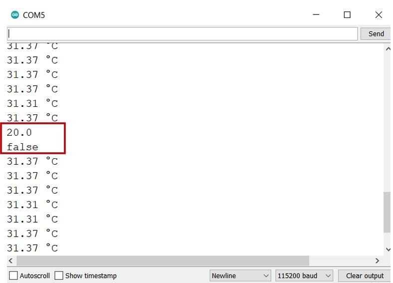
Serial.println(input_field);
Serial.println(input_field2);
request->send(200, "text/html", "HTTP GET request sent to your ESP.<br><a href=\"/\">Return to Home Page</a>");
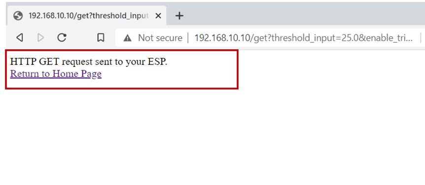
});When the user clicks the submit button the send() method will be used to return the HTTP response. It takes in three parameters. The first parameter is the response code which we will specify as 200. It is the HTTP response code for ok. The second parameter is the content type of the response which we will specify as “text/html” and the third parameter is the actual message which we will be sent as the HTTP response. This is set as “HTTP GET request sent to your ESP.<br><a href=\”/\”>Return to Home Page</a>”. The arrow operator will be used to call the send method on the AsyncWebServerRequest object. A new web page will open which will contain a link to go back to the main web page.
request->send(200, "text/html", "HTTP GET request sent to your ESP.<br><a href=\"/\">Return to Home Page</a>");To start the server, we will call begin() on our server object.
server.begin();loop()
Inside the loop() function, we will access temperature readings after every 10 seconds and send email alerts based on the temperature threshold.
The following lines of code check for the delay between the sensor readings and display them on the serial monitor after every 10 seconds. Firstly, we will call the requestTemperatures() method. Then we will use the getTempCByIndex() function to retrieve the temperature in degrees Celsius. Notice that we are passing 0 as a parameter inside the function. This is because we are using a single DS18B20 sensor.
unsigned long currentMillis = millis();
  if (currentMillis - previousMillis >= interval) {
    previousMillis = currentMillis;
    sensors.requestTemperatures();
    float temperature = sensors.getTempCByIndex(0);
    Serial.print(temperature);
    Serial.println(" °C");

last_temperature = String(temperature);
Now, through if-else if statements, we will check if the current temperature reading is above or below the threshold temperature set by the user.
The output will be set to HIGH if all three conditions are met. Firstly, the current temperature should be above the threshold temperature. Secondly, the trigger should be enabled i.e., the user ticks the checkbox on the web server. Lastly, the output has not been triggered yet.
 if(temperature > input_field.toFloat() && input_field2 == "true" && !triggerActive){
      String message = String("Temperature above threshold. Current temperature: ") +
                            String(temperature) + String("C");
      Serial.println(message);
      triggerActive = true;
      digitalWrite(ESP_output, HIGH);
    }
Likewise, the output will be set to LOW if all three conditions are met. Firstly, the current temperature should be below the threshold temperature. Secondly, the trigger should be enabled i.e., the user ticks the checkbox on the web server. Lastly, the output has already been triggered before.
 else if((temperature < input_field.toFloat()) && input_field2 == "true" && triggerActive) {
      String message = String("Temperature below threshold. Current temperature: ") +
                            String(temperature) + String(" C");
      Serial.println(message);
      triggerActive = false;
      digitalWrite(ESP_output, LOW);
    }
Demonstration
After you have uploaded your code to the ESP32/ESP8266 development board press its ENABLE/RST button.


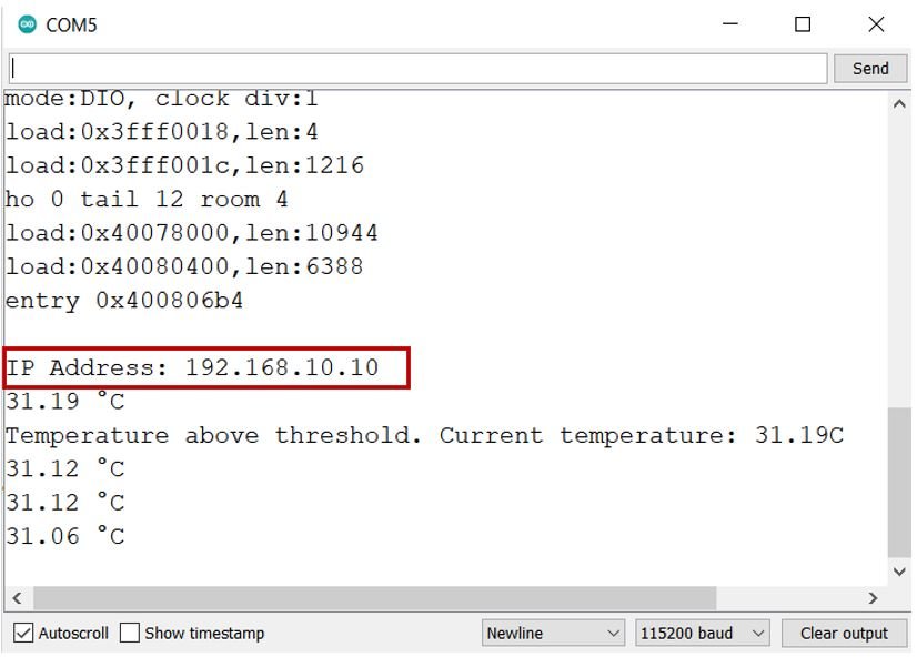
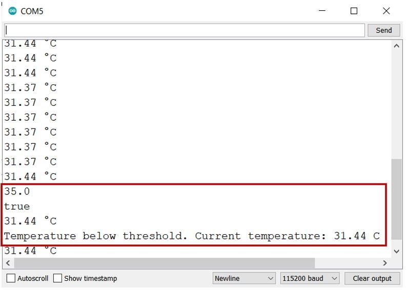
In your Arduino IDE, open up the serial monitor and you will be able to see the IP address of your ESP module. New temperature readings will also display after every 10 seconds.
Type that IP address in a web browser and press enter.
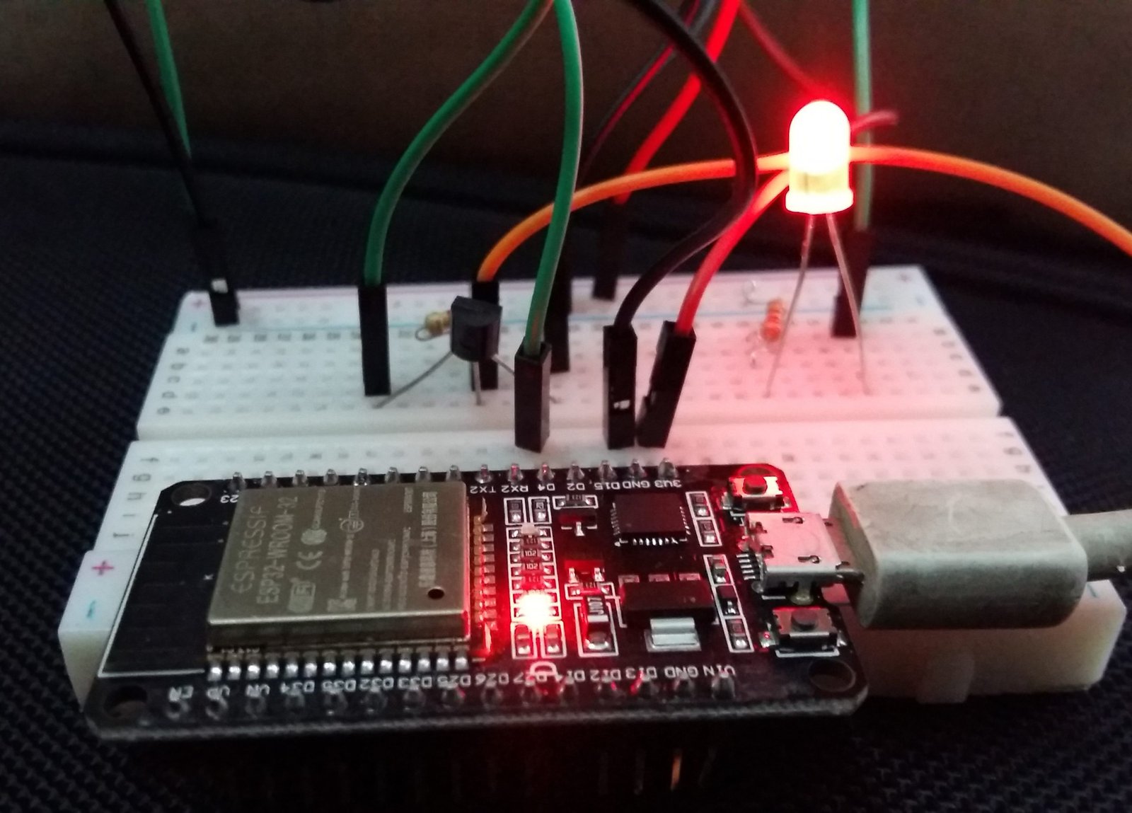
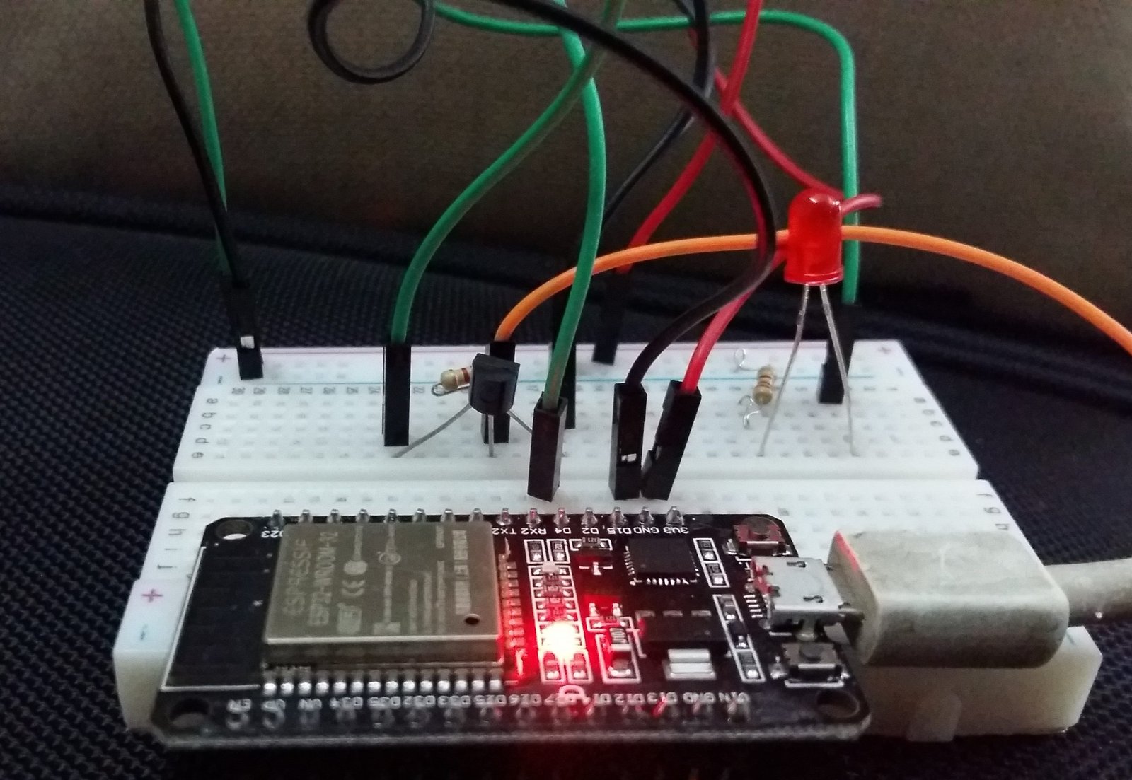
Now, fill in the input fields or leave them as default. As our current temperature is higher than the set threshold value and we had enabled the trigger hence LED turned ON. The serial monitor also displays the message that the current temperature is above a threshold.
Now, we changed the threshold value to 35 degrees Celsius keeping the checkbox checked. Press the submit button for the changes to take place.
We will be redirected to a new web page as shown below. Click the link below to redirect to the main web page.
In the serial monitor, you can view the changes which took place. The LED will now turn OFF.
Likewise, now you can change the threshold temperature but uncheck the trigger checkbox. This will deactivate the system meaning now the LED will not turn ON if the current temperature goes above the threshold temperature.
The serial monitor will also display the changes.
Conclusion
In conclusion, we created an ESP32 and ESP8266 thermostat web server with a temperature threshold input. We were able to control ESP32/ESP8266 outputs whenever the current temperature went above or below the threshold temperature. You can use any appropriate sensor such as BME680, BME280, DHT11, MPU6050, and DHT22 with your ESP board to build a similar thermostat web server.
You may also like to read the following content:
- ESP32/ESP8266 HTTP Authentication Web Server (Username and Password Protected)
- Send Email Alert Based on Temperature Threshold and Update Threshold value with ESP32 Web Server
- ESP32/ESP8266 Control Outputs with Web Server and Push Button Simultaneously
- Telegram ESP32 and ESP8266: Control GPIOs and LEDs using Arduino IDE
- ESP32/ESP8266 Momentary Switch Web Server: Control GPIO Outputs
- Displaying Images in ESP32 and ESP8266 Web Server
- ESP32/ESP8266 Web Server to Control Outputs with a Timer (Pulse Width)
Excelente tutorial! Parabéns.
Carlos Bruni
Salvador Bahia Brasil
Hello, it already exists with DS1820 and outputs. I have difficulties to build it because it can be operated with 2 sensors. Kind regards