In this tutorial, we will perform UART or serial communication between two ESP32 boards using UART hardware library of Arduino IDE. To debug and program ESP32 using a USB port, the serial port which is known as Universal Asynchronous Receiver/Transmitter (UART) Communication is used. For most sensors and systems, the main communication method is considered to be UART. In order to share workload, information and perform different tasks, sometimes communication between two ESP32 boards is required.
We will use Arduino IDE to program our ESP32 development board. Thus, you should have the latest version of Arduino IDE. Additionally, you also need to install the ESP32 plugin.
If your IDE does not have the plugin installed you can visit the link below: Installing ESP32 library in Arduino IDE and upload code.
Recommended Components
The following components are used in this project or are helpful for building it with the ESP32.
| Component | How it’s used in this project | Buy on Amazon |
|---|---|---|
| ESP32 Development Board | Two of these boards run the master and slave sketches and communicate over UART2. | Check Price |
| Micro USB Cable | Programs each ESP32 and powers it during testing. | Check Price |
| Breadboard | Holds the LED and wiring for the slave board without soldering. | Check Price |
| Jumper Wires | Connect the TX/RX lines between the two boards and to the LED. | Check Price |
| 5mm LED | Driven by the slave ESP32 to show the received serial data. | Check Price |
| Resistor Kit (220 Ω / 4.7k) | A 220 Ω resistor limits current to the LED. | Check Price |
As an Amazon Associate we earn from qualifying purchases. Prices and availability are accurate as of the date/time indicated and are subject to change.
UART Introduction
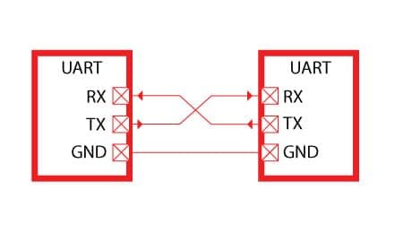
Universal Asynchronous Receive Transmit (UART) or Serial communication is one of the most simple communication protocols between two devices. It transfers data between devices by connecting two wires between the devices, one is the transmission line while the other is the receiving line. The data transfers bit by bit digitally in form of bits from one device to another. The main advantage of this communication protocol is that its not necessary for both the devices to have the same operating frequency. For example, two microcontrollers operating at different clock frequencies can communicate with each other easily via serial communication. However, a predefined bit rate that is referred to as baud rate usually set in the flash memory of both microcontrollers for the instruction to be understood by both the devices.
Transmitting and receiving serial data
The transmitting UART takes bytes of data and transmits the bits in a sequential form. The second transmitter which is the receiver reassembles the bits into a complete byte. Serial transmission of data through a single wire is actually more cost-effective than parallel transmission through multiple wires.
Communication between two UART devices may be simplex, full-duplex or half-duplex. Simplex communication is a one-direction type of communication where the signal moves from one UART to another. It doesn’t have provision for the receiving UART to send back signals. A full-duplex is when both devices can transmit and receive communications at the same time. A half-duplex is when devices take turns to transmit and receive.
Structure of a UART Protocol
- A UART contains a clock generator. This allows the sampling in a bit period.
- It also contains input and output shift registers.
- Transmitting and receiving control.
- A read or write control logic.
- Other optional components of a UART are: transmit or receive buffers, FIFO buffer memory, and a DMA controller.
UART technology
There was a time not so long ago when keyboards, mice, and printers had thick cables and clunky connectors. These had to be literally screwed into the computer. These devices where using UART to communicate with computers. Although these clunky cables have been replaced with USB, you can still find UARTs being used in DIY electronics such as Raspberry Pi, Arduino, and other common microcontrollers. We can use it to connect Bluetooth modules and GPS modules.
UART has a different transfer protocol than other communication protocols such as SPI and I2C. It is a physical circuit fount in a microcontroller. It can also function as a stand-alone integrated circuit. One significant advantage of UART is that it only relies on two wires to transmit data.
How do two Device Communicate through UART?
It takes two UART’s to communicate directly with each other. On one end the transmitting UART converts parallel data from a CPU into serial form then transmits the data in serial form to the second UART which will receive the serial data and convert it back into parallel data. This data can then be accessed from the receiving device.
Instead of cloak signals the transmitting and receiving bit use start and stop bit signals for the data packages. These start and stop bits define the beginning and the end of the data packages. Therefore the receiving UART knows when to start and stop reading the bits.
The Receiving UART will detect the start bit then start reading the bits. The specific frequency used to read the incoming bits is known as the baud rate. The baud rate is a measure used for the speed of data transfer. The unit used for baud rate is bits per second (bps). In order for the data transfer to be a success both the transmitting and receiving UART must operate at almost the same baud rate. However, if the baud rates differ between both UARTs they must only differ by 10%. The receiving and transmitting UART must be configured to receive the same data packages.
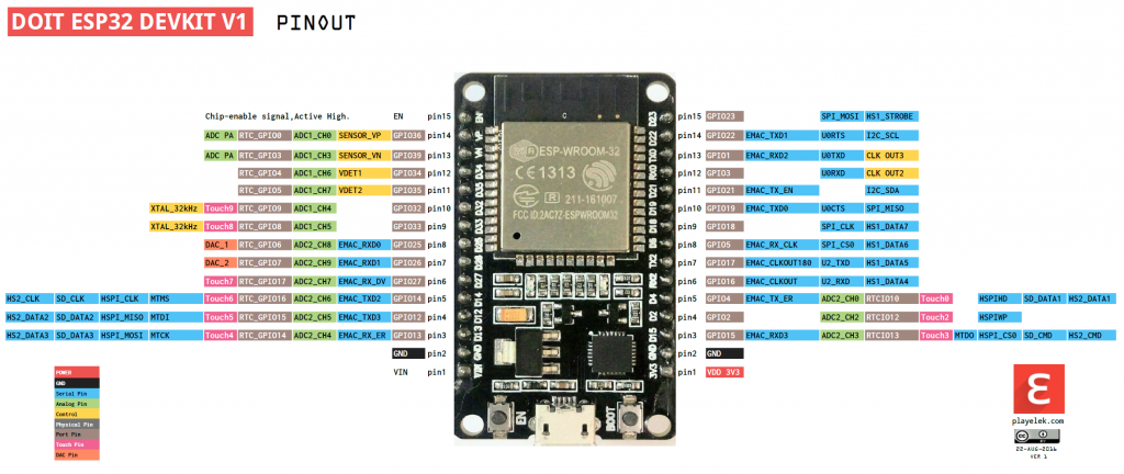
ESP32 UART Pins
ESP32 provides three universal asynchronous receivers and transmitter (UART) ports such as UART0, UART1, and UART2 that work at 3.3V TTL level. These three serial interfaces are hardware supported. Each of them exposes 4 pins: RX, TX, RTS and CTS. However, the Arduino IDE only uses RX and TX pins.
By default, only UART0 and UART2 can be used. To use UART1, we have to redefine the pins because default pins of UART1 such as GPIO9 and GPIO10 are internally connected to the SPI flash memory. Also, on some ESP32 boards, they are even exposed on the pinout headers. Hence, we can not use UART1 directly without reassigning pins in Arduino IDE.
The table below specifies the RX and TX pins for each of the three UART ports available in ESP32.
| UART Port | Rx | Tx | Useable |
|---|---|---|---|
| UART0 | GPIO3 | GPIO1 | Yes |
| UART1 | GPIO9 | GPIO10 | Yes but requires the reassignment of pins |
| UART2 | GPIO16 | GPIO17 | Yes |
Initializing ESP32 UART in Arduino IDE
We use the HardwareSerial library when working with ESP32 UART communication using UART1 or UART2 ports. So, firstly include the library in the script.
#include <HardwareSerial.h>Next, if we use Serial.begin(), then pins 1 and 3 are used, which means that we are using UART0. If we want to use other serial ports, then we will have to define them in code. We use the following commands to define our selected UART port:
Here we create an object of the HardwareSerial library called ‘SerialPort()’ and specify the UART port inside the parenthesis.
Serial.begin()   //if using UART0
HardwareSerial SerialPort(1)  //if using UART1
HardwareSerial SerialPort(2)  //if using UART2
Next, inside the setup() function, we will initialize the UART communication using the SerialPort object on the begin() method and specify four parameters inside it as follows:
SerialPort.begin (BaudRate, SerialMode, RX_pin, TX_pin).The parameters include the baud rate for serial communication, the serial mode, the RX pin and the TX pin being used.
If using UART2, we will initialize it as follows:
#include <HardwareSerial.h>

HardwareSerial SerialPort(2); // use UART2

void setup()
{
  SerialPort.begin(15200, SERIAL_8N1, 16, 17);
}
If using UART1, we will initialize it as follows:
An important point to note here is that GPIO pin 9 and pin 10 which are part of UART1 TX and RX pins, are internally connected to the flash memory. Moreover, these pins are also not available on the ESP32 boards. Hence, we will have to reassign the pins for UART1 for serial communication. Luckily, the ESP32 board is capable to use almost all GPIO pins for serial connections. Here we have reassigned GPIO4 as RX pin and GPIO2 as TX pin.
#include <HardwareSerial.h>

HardwareSerial SerialPort(1); // use UART1

void setup()
{
  SerialPort.begin(15200, SERIAL_8N1, 4, 2);
}
ESP32 to ESP32 Serial Communication
Let us see an example of serial communication where the ESP32 master will send either ‘1’ or ‘0’ to the ESP32 slave. The slave will then receive that data and control an LED connected with its digital pin. We will use UART2 to communicate between the two boards.
You will require the following components for this project.
Required Components
- Two ESP32 development boards
- One 5mm LED
- One 220 ohm resistor
- Connecting Wires
- Breadboard
Connection Diagram

Connect TX2 pin of master ESP32 board with RX2 pin of slave ESP32 board. Likewise, connect RX2 pin of master ESP32 board with TX2 pin of slave ESP32 board.
Anode pin of LED is connected with digital pin15 (slave) through a 220 ohm current limiting resistor. The cathode pin is grounded.
Also make sure both ESP32 boards have their grounds in common.

Master ESP32 Arduino Sketch
Open your Arduino IDE and go to File > New to open a new file. Copy the code given below and save it.
#include <HardwareSerial.h>

HardwareSerial SerialPort(2); // use UART2


void setup()
{
  SerialPort.begin(15200, SERIAL_8N1, 16, 17);
}
void loop()
{
  SerialPort.print(1);
  delay(5000);
  SerialPort.print(0);
  delay(5000);
}
How the Code Works?
Now lets see how above code works.
First include the hardware serial library using #include files. This line includes the HardwareSerial.h library.
#include <HardwareSerial.h>A serial object of the HardwareSerial library, named as “SerialPort” is declared here. We specify the UART port number as a parameter inside it. We are using UART2 in this case.
HardwareSerial SerialPort(2); // use UART2Inside the setup() function, we will open the serial communication of port UART2 using SerialPort.begin (BaudRate, SerialMode, RX_pin, TX_pin).
void setup()
{
  SerialPort.begin(15200, SERIAL_8N1, 16, 17);
  }
Here the master will send the number 1 and 0 to the slave after every 5 seconds.
void loop()
{
  SerialPort.print(1);
  delay(5000);
  SerialPort.print(0);
  delay(5000);
}
Slave ESP32 Arduino Sketch
Open your Arduino IDE and go to File > New to open a new file. Copy the code given below and save it.
#include <HardwareSerial.h>

HardwareSerial SerialPort(2); // use UART2


char number  = ' ';
int LED = 15;

void setup()
{
  SerialPort.begin(15200, SERIAL_8N1, 16, 17);
  pinMode(LED, OUTPUT);
}
void loop()
{
  if (SerialPort.available())
  {
    char number = SerialPort.read();
    if (number == '0') {
      digitalWrite(LED, LOW);
    }
    if (number == '1') {
      digitalWrite(LED, HIGH);
    }
  }
}
How the Code Works?
First include the hardware serial library.
#include <HardwareSerial.h>A serial object of the HardwareSerial library, named as “SerialPort” is declared here. We specify the UART port number as a parameter inside it. We are using UART2 in this case.
HardwareSerial SerialPort(2); // use UART2A char variable called ‘number’ stores the data that the slave will receive from the master.
char number = ' ';The LED is connected with the slave ESP32 GPIO15.
int LED = 15;Inside the setup() function, we will open the serial communication of port UART2 using SerialPort.begin (BaudRate, SerialMode, RX_pin, TX_pin). Also, set the LED pin as an output pin using the pinMode() function. Specify the pin as the first parameter and the mode as the second parameter.
One important point to note here is that the baud rate of both ESP32 master and slave boards should be the same.
void setup()
{
  SerialPort.begin(15200, SERIAL_8N1, 16, 17);
  pinMode(LED, OUTPUT);
}
Inside the loop() function, we will check if data is present in the buffer. If some data is available, it is stored in variable ‘number.’ If the number is ‘0’, then turn the LED will be turned OFF. If the number is ‘1’, then the LED will be turned ON.
The master will send ‘1’ and ‘0’ with a delay of 5 seconds continuously to the slave. Hence, the LED will stay ON for 5 seconds and then OFF for 5 seconds.
void loop()
{
  if (SerialPort.available())
  {
    char number = SerialPort.read();
    if (number == '0') {
      digitalWrite(LED, LOW);
    }
    if (number == '1') {
      digitalWrite(LED, HIGH);
    }
  }
}
Hardware Demonstration
To see the demonstration, upload the master and sender codes to the two ESP32 boards. But, before uploading code, make sure to select the ESP32 Dev Module from Tools > Board and also select the correct COM port to which the board is connected from Tools > Port.
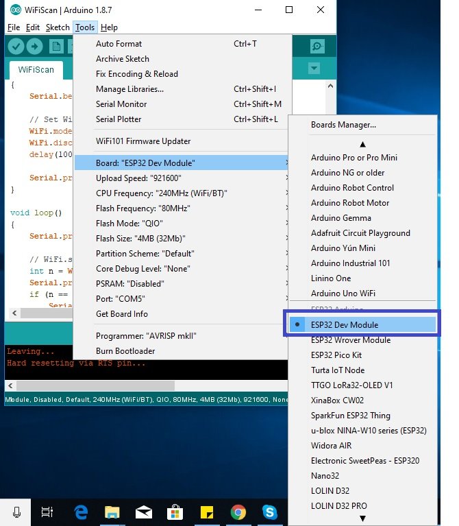

The LED will turn ON and stay ON for 5 seconds before turning OFF for 5 seconds. This continues as the master keeps on sending 1/0 to the slave.

Watch the video below:
Votre site est vraiment excellent, j’ai appris beaucoup de choses quoique je ne maîtrise pas beaucoup l’anglais.
Merci et continuez à visiter notre site Web pour des tutoriels plus utiles
Great information well explained …. Thanks
Hello, thank you very much for this very good tutorial!!!.
I have a question: I need 2 ESP3 to talk full duplex. ESP32 number 1 sends the request and ESP32 number 2 replies when finished. Is it possible to do this with one UART channel or 2 must be defined. Please, show me a solution path.
Thank you very much.
Pedro
Pedro Bravo,
I have read other posts by you on this ” full-duplex ESP32″ question. I too am having some trouble doing this.
Have you found a solution that works for you?
… and if so, could you please share it with me?
Thanks
Greg
my slave esp32 usb is broken is there is any way to upload sketch on it
Should I use software serial if I want to use 12 and 15 pins as rx and tx respectively??
Hey, could you change “Serial.begin()” to e.g. “Serial.begin(115200)” or “Serial.begin(BAUD)” or something? It took me like, over an hour to figure out the message about HardwareSerial was ACTUALLY talking about my call to “Serial.begin()”, because I forgot it needed a baud specified.
I lost whole day but could not succeed in sending AT command using SoftwareSerial, I have ESP32 Dev Unit
SoftwareSerial lora(16, 17);
const int NETWORKID_LORA=5; //enter Lora Network ID
const int ADDRESS_LORA_NODE_GATEWAY=1;
lora.begin(115200); // default baud rate of module is 115200
delay(1000); // wait for LoRa module to be ready
lora.print((String)”AT+ADDRESS=” + ADDRESS_LORA_NODE_GATEWAY + “\r\n”);
delay(200);
lora.print((String)”AT+NETWORKID=” + NETWORKID_LORA + “\r\n”);
delay(200);
Please help
hi, I was wondering if the baud rate can be higher than 115200 for uart1 and uart2?
Gracias, muy bien explicado!!!!
Excelente… Eres o son muy buenos, estaba estancado justo en este tema y leer esta explicación fue como ver la luz al final del túnel.