In this tutorial, we will learn about MAX30100 pulse oximeter and heart rate sensor and how to interface it with ESP32. This sensor is used to measure heartbeat/pulse rate in BPM and blood oxygen concentration (SpO2) in percentage. Firstly, we will discuss the introduction, pinout, working, and connection diagram of the sensor with ESP32 development board. After that, we will see different examples such as finding BPM, oxygen saturation, plotting data on serial monitor, presence sensing, and temperature measurement.
We have similar guides with Arduino Uno and ESP8266 NodeMCU:
- MAX30100 Pulse Oximeter and Heart Rate Sensor with ESP8266
- MAX30100 Pulse Oximeter and Heart Rate Sensor with Arduino
Recommended Components
The following components are used in this project or are helpful for building it with the ESP32.
| Component | How it’s used in this project | Buy on Amazon |
|---|---|---|
| ESP32 Development Board | Reads the pulse oximeter / heart rate sensor over I2C. | Check Price |
| Micro USB Cable | Programs and powers the ESP32. | Check Price |
| Breadboard | Holds the ESP32 and sensor for wiring. | Check Price |
| Jumper Wires | Connect the I2C lines between the sensor and ESP32. | Check Price |
As an Amazon Associate we earn from qualifying purchases. Prices and availability are accurate as of the date/time indicated and are subject to change.
MAX30100 Pulse Oximeter Sensor Introduction
The MAX30100 sensor is used as both heart rate monitor and a pulse oximeter. These features are enabled by the construction of this sensor which consists of two LEDs, a photodetector, optimized optics, and low noise signal processing components. It is easily used with microcontrollers such as Arduino, ESP32, NodeMCU, etc. to build an efficient heartbeat and oxygen saturation device.
This sensor is mostly available in two different versions: GY-MAX30100 and RCWL-0530.


In this guide we will focus on RCWL-0530 as it is a little tricky to work with due to a design issue that we will later see how to resolve. The GY-MAX30100 sensor on the other hand is a very easy to use sensor with no additional problems.
Let us look at the overview of this sensor.
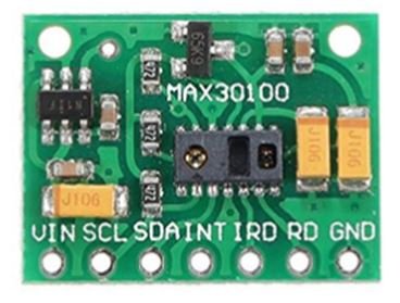
Below you can view the diagram of RCWL-0530.

As you may notice the MAX30100 IC lies at the centre of the module. It consists of two different types of LEDs on the right hand side. There is one Red LED and one IR LED. On the left hand side you can view the photodetector. Blood oxygen saturation and heart rate are found using these these two key features. We will later learn how the sensor actually works to obtain the BPM and SPO2.
Another important feature you may notice is that the MAX30100 sensor module consists of two LDO regulators. This is because the MAX30100 IC requires 1.8V and the LEDs require 3.3V to function properly. With the addition of the voltage regulators, we can safely use microcontrollers that use 5/3.3/1.8V level input/outputs.
Key Features
- The MAX30100 sensor module has an ultra low power operation, uses 600μA (measurement mode and 0.7μA(standby mode). Therefore a great choice to use in wearable devices such as smart watches etc.
- It has a high sample rate capability along with fast data output capability.
- Additionally, the sensor features integrated ambient light cancellation as well.
- One additional feature that the MAX30100 sensor module possess is the inclusion of an on-chip temperature sensor. This gives us the die temperature (-40˚C to +85˚C) which is ± 1˚C accurate.
- For communicating with microcontrollers, the sensor uses the I2C pins SCL and SDA.
- Another feature of this sensor is that it uses a 16 sample FIFO buffer to store data. In other words, it further reduces power consumption as it already holds maximum of sixteen heart rate and SPO2 values.
- The MAX30100 can also be used with interrupts which can be enabled for several sources such as power ready, SPO2 data ready, heart rate data ready, temperature ready and FIFO almost full. With the generation of interrupts, the microcontroller can perform other events which do not happen during the sequential execution of a program while the sensor keeps obtaining new data samples.
The table below shows the specifications of this sensor:
| Operating Voltage | 1.8V to 3.3V |
| Input Current | 20mA |
| Temperature Range | -40˚C to +85˚C |
| Temperature Accuracy | ±1˚C |
| ADC Resolution | 14 bits |
| IR LED peak wavelength | 870-900nm |
| Red LED peak wavelength | 650-670nm |
For more information about the specifications, refer to the MAX30100 Datasheet.
MAX30100 Pulse Oximeter Working
In this section, let us discuss how the MAX30100 heart beat monitor and pulse oximeter actually works.
Pulse Oximeter
To find the blood oxygen concentration (%), it is first important to know that inside our blood hemoglobin is responsible for carrying oxygen. When a person holds a pulse oximeter, light from the device passes through the blood in the fingers. This is used to detect the amount of oxygen by measuring the changes in light absorption in both oxygenated and deoxygenated blood.
As we already mentioned before, the MAX30100 sensor consists of two LEDs (Red and IR) and a photodiode. Both of these LEDs are used for SPO2 measurement. These two LEDs emit lights at different wavelengths, ~640nm for the red led and ~940nm for the IR LED. At these particular wavelengths, the oxygenated and deoxygenated hemoglobin have vastly different absorption properties.
The diagram below is taken from the datasheet of MAX30100 IC. You may notice the difference shown in the graph between HbO2 which is oxygenated hemoglobin and Hb which is deoxygenated hemoglobin at two different wavelengths.
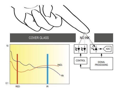
The oxygenated hemoglobin absorbs more infrared light and reflects back the red light whereas the deoxygenated hemoglobin absorbs more red light and reflects back the infrared light. The reflected light is measured by the photodetector. The MAX30100 sensor reads these different absorption levels to find the blood oxygen concentration (SPO2). The ratio of IR and RED light received by the photodetector gives us the blood oxygen concentration.
Heart Rate Measurement
To measure the heart rate, we do not require the Red LED, only the IR LED is needed. This is because oxygenated hemoglobin absorbs more infrared light.
The heartbeat rate is the ratio of time between two consecutive heartbeats. Similarly, when the human blood is circulated in the human body then this blood is squeezed in capillary tissues. As a result, the volume of capillary tissues is increased but this volume is decreased after each heartbeat. This change in volume of capillary tissues affects the infrared light of the sensor, which transmits light after each heartbeat.
The working of this sensor could be checked by placing a human finger in front of this sensor. When a finger is placed in front of this pulse sensor then the reflection of infrared light is changed based on the volume of blood change inside capillary vessels. This means during the heartbeat, the volume of blood in capillary vessels will be high and then will be low after each heartbeat. So, by changing this volume, the LED light is changed. This change of the LED light measures the heartbeat rate of a finger. This phenomenon is known as “Photoplethysmogram.”
MAX30100 Pulse Oximeter Pinout
The MAX30100 module (RCWL-0530) consists of seven pins.
| Pin | Description |
|---|---|
| Pin | Description |
| VIN | This pin is used to supply power to the sensor. This sensor is powered on at 3.3-5V. |
| SCL | This is the I2C serial clock pin. |
| SDA | This is the I2C serial data pin. |
| INT | This is the active low interrupt pin. It is pulled HIGH by the onboard resistor but when an interrupt occurs it goes LOW until the interrupt clears. |
| IRD | IR LED Cathode and LED Driver Connection Point |
| RD | Red LED Cathode and LED Driver Connection Point |
| GND | This is used for supplying ground to this sensor and it is connected to the source ground pin. |
Interfacing MAX30100 Pulse Oximeter with ESP32
In this section, we will learn how to interface MAX30100 sensor module with ESP32 board.
Design Problem with RCWL-0530
Before we move forward, you may remember that we mentioned before that the RCWL-0530 version has a serious design issue. Let us see how to resolve that first.
You can view the schematic diagram of the module below:

MAX30100 sensor module consists of two LDO regulators. This is because the MAX30100 IC requires 1.8V and the LEDs require 3.3V to function properly. Now refer to the schematic diagram of the module and notice that the SDA, SCL and INT lines are connected to 1.8V via 4.7k ohm pull up resistors. This is a serious design issue because now the sensor will not properly work with microcontrollers with higher logic levels e.g. ESP32 in our case. The I2C device will not be recognized.
There are two ways to resolve this problem.
Solution 1: Remove the 4.7k pull up resistors from the module and connect external resistors instead
One way to resolve the issue stated above is to remove the three pull-up resistors shown in the diagram below and use external ones instead.

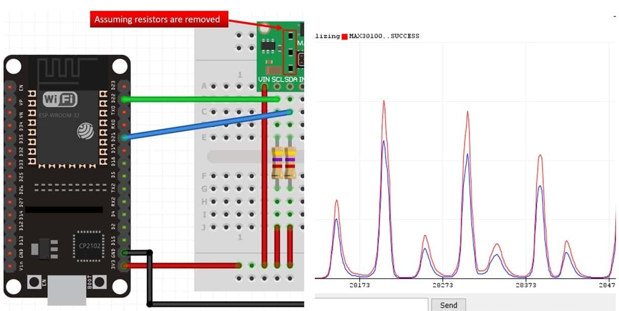
You can easily remove them using a soldering iron. After you have removed the resistors, you are good to go and can connect your module with ESP32 as shown below:
Here we are connecting SDA and SCL pins to 3.3V from ESP32 via external 4.7k ohm resistors. The rest of the connections are shown in the table below:
| MAX30100 Module | ESP32 |
|---|---|
| VCC | 3.3V |
| SCL | GPIO22 |
| SDA | GPIO21 |
| GND | GND |
Solution 2: Cut the path and make a new path
The second solution is to disconnect the 4.7k ohm pull-up resistors from 1.8V by cutting that path and making a path such that the pull-up resistors connect to 3.3V instead.

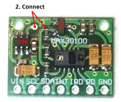
Cut the path between the 4.7k ohm resistor and the 1.8V LDO regulator. Then connect a jumper wire or solder a path between the 3.3V LDO regulator and the 4.7k ohm resistor as shown in the picture above.
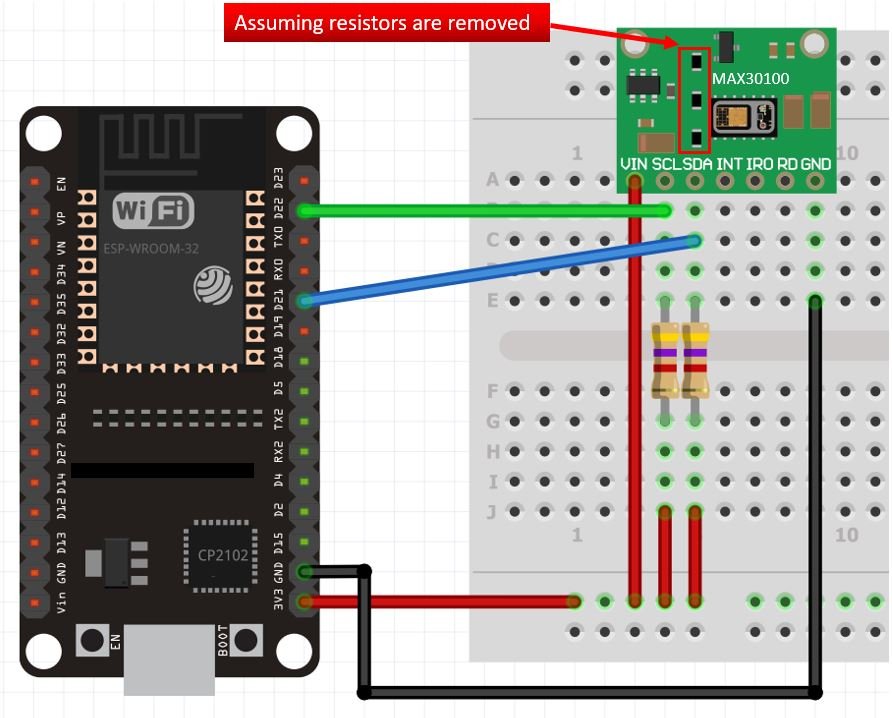
After you have made the changes, you can connect your module with ESP32 as shown below:
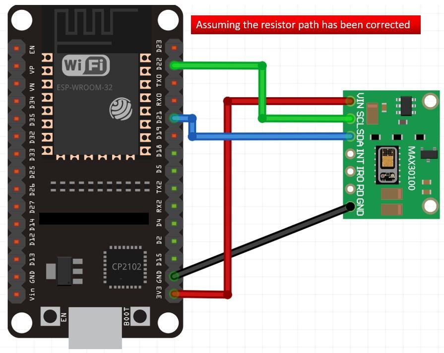
The connections between the sensor module and ESP32 are as follows:
| MAX30100 Module | ESP32 |
|---|---|
| VCC | 3.3V |
| SCL | GPIO22 |
| SDA | GPIO21 |
| GND | GND |
Installing MAX3100 Arduino Library
We will use Arduino IDE to program our ESP32 development board. Thus, you should have the latest version of Arduino IDE. Additionally, you also need to install the ESP32 plugin.
If your IDE does not have the plugin installed you can visit the link below: Installing ESP32 library in Arduino IDE and upload code.
Open Arduino IDE and click on Sketch > Library > Manage Libraries
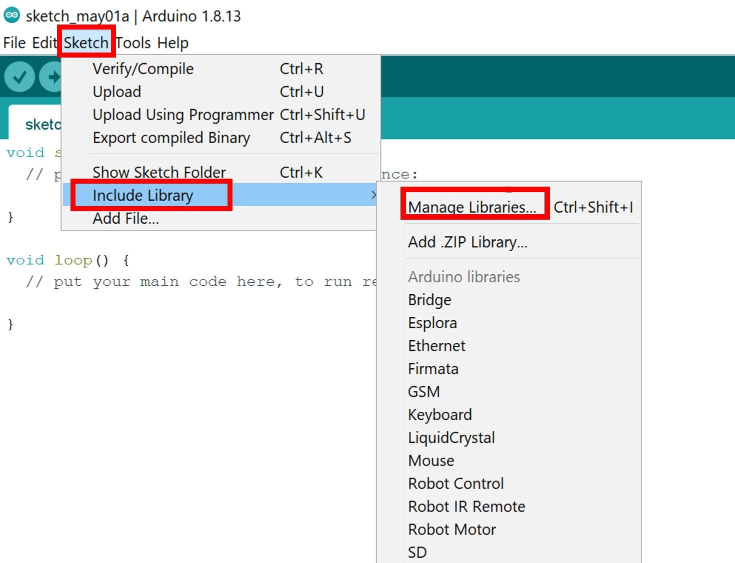
The following window will open up.

Type ‘ max30100’ in the search bar and press enter. Install the latest version of the library: MAX30100lib Library by OXullo Intersecans.

After the installation of the library, restart your IDE.
MAX30100 Sensor Sketches for ESP32
In this section, we will show you how to use different sketches in the Arduino IDE using MAX30100lib library that we just installed. We will look at different sketches to effectively learn how to use the MAX30100 sensor with our ESP32 board.
Measure Heart Rate(BPM) and Blood Oxygen Concentration (SPO2) using MAX30100
Open your Arduino IDE and go to File > New to open a new file. Copy the code given below and save it.
This sketch will display the BPM and SPO2 values in the serial monitor when you hold the sensor in between your fingers.
#include <Wire.h>
#include "MAX30100_PulseOximeter.h"

#define REPORTING_PERIOD_MS     1000

// Create a PulseOximeter object
PulseOximeter pox;

// Time at which the last beat occurred
uint32_t tsLastReport = 0;

// Callback routine is executed when a pulse is detected
void onBeatDetected() {
    Serial.println("♥ Beat!");
}

void setup() {
    Serial.begin(115200);

    Serial.print("Initializing pulse oximeter..");

    // Initialize sensor
    if (!pox.begin()) {
        Serial.println("FAILED");
        for(;;);
    } else {
        Serial.println("SUCCESS");
    }

  // Configure sensor to use 7.6mA for LED drive
  pox.setIRLedCurrent(MAX30100_LED_CURR_7_6MA);

    // Register a callback routine
    pox.setOnBeatDetectedCallback(onBeatDetected);
}

void loop() {
    // Read from the sensor
    pox.update();

    // Grab the updated heart rate and SpO2 levels
    if (millis() - tsLastReport > REPORTING_PERIOD_MS) {
        Serial.print("Heart rate:");
        Serial.print(pox.getHeartRate());
        Serial.print("bpm / SpO2:");
        Serial.print(pox.getSpO2());
        Serial.println("%");

        tsLastReport = millis();
    }
}
How the Code Works?
Now let us understand how the code is working.
Firstly, we include the necessary libraries for this project:
#include <Wire.h>
#include "MAX30100_PulseOximeter.h"
Next we define the reporting time in ms between the samples.
#define REPORTING_PERIOD_MS 1000Here we are creating an object ‘pox’ of PulseOximeter.
PulseOximeter pox;The following variable holds the time when the last beat occurred.
uint32_t tsLastReport = 0;The following callback function will display “♥ Beat!” in the serial monitor when a heart beat occurs.
void onBeatDetected() {
    Serial.println("♥ Beat!");
}
setup()
Inside the setup() function, we first open the serial communication at a baud rate of 115200. Then we initialize the MAX30100 sensor module. A relevant message will be displayed in the serial monitor.
Serial.begin(115200);

    Serial.print("Initializing pulse oximeter..");

    // Initialize sensor
    if (!pox.begin()) {
        Serial.println("FAILED");
        for(;;);
    } else {
        Serial.println("SUCCESS");
    }
Then we set the current value for LED drive by using the PulseOximeter object on setIRLedCurrent() method. Here we have configured the sensor to use 7.6mA for the IR LED.
pox.setIRLedCurrent(MAX30100_LED_CURR_7_6MA);By default, the current is set to 50mA which may cause problems in initialization so we set a lower value instead.
You can use the following values inside the function:
- MAX30100_LED_CURR_0MA
- MAX30100_LED_CURR_4_4MA
- MAX30100_LED_CURR_7_6MA
- MAX30100_LED_CURR_11MA
- MAX30100_LED_CURR_14_2MA
- MAX30100_LED_CURR_17_4MA
- MAX30100_LED_CURR_20_8MA
- MAX30100_LED_CURR_24MA
- MAX30100_LED_CURR_27_1MA
- MAX30100_LED_CURR_30_6MA
- MAX30100_LED_CURR_33_8MA
- MAX30100_LED_CURR_37MA
- MAX30100_LED_CURR_40_2MA
- MAX30100_LED_CURR_43_6MA
- MAX30100_LED_CURR_46_8MA
- MAX30100_LED_CURR_50MA
Lastly, we register our callback function onBeatDetected as well through the following line of code:
pox.setOnBeatDetectedCallback(onBeatDetected);loop()
Inside the loop() function, we will first read from the sensor using pox.update(). Then we will obtain the readings for the heart rate and the blood oxygen concentration and print them in the serial monitor after every second. To obtain the heart rate reading, use the PulseOximeter object on the getHeartRate() method. Similarly, to obtain the blood oxygen concentration, use the PulseOximeter object on the getSpO2() method.
void loop() {

    pox.update();


    if (millis() - tsLastReport > REPORTING_PERIOD_MS) {
        Serial.print("Heart rate:");
        Serial.print(pox.getHeartRate());
        Serial.print("bpm / SpO2:");
        Serial.print(pox.getSpO2());
        Serial.println("%");

        tsLastReport = millis();
    }
}
Demonstration
Choose the correct board and COM port before uploading your code to the board.
Go to Tools > Board and select ESP32 Dev Module.

Next, go to Tools > Port and select the appropriate port through which your board is connected.

Click on the upload button to upload the code into the ESP32 development board. After you have uploaded your code to the ESP32 development board press its ENABLE button.

Now hold the sensor in between your fingers. Do not hold it very tightly or very lightly. Make sure you apply normal pressure while holding the sensor. This will result in a better clean signal.
The BPM and SpO2 readings will update after every second. Additionally, you can also view when a heart beat is detected.

Plot MAX30100 Raw Data Values
In the next sketch, we will obtain the raw IR LED and Red LED values and plot them in the serial plotter.
Open your Arduino IDE and go to File > New to open a new file. Copy the code given below and save it.
#include <Wire.h>
#include "MAX30100_PulseOximeter.h"

// Create a MAX30100 object
MAX30100 sensor;

void setup() {
    Serial.begin(115200);

    Serial.print("Initializing MAX30100..");

    // Initialize sensor
    if (!sensor.begin()) {
        Serial.println("FAILED");
        for(;;);
    } else {
        Serial.println("SUCCESS");
    }

  sensor.setMode(MAX30100_MODE_SPO2_HR);
  sensor.setLedsCurrent(MAX30100_LED_CURR_50MA, MAX30100_LED_CURR_27_1MA);
  sensor.setLedsPulseWidth(MAX30100_SPC_PW_1600US_16BITS);
  sensor.setSamplingRate(MAX30100_SAMPRATE_100HZ);
  sensor.setHighresModeEnabled(true);
}


void loop() {
  uint16_t ir, red;

  sensor.update();

  while (sensor.getRawValues(&ir, &red)) {
    Serial.print(red);
    Serial.print(", ");
    Serial.println(ir);
  }
}
How the Code Works?
Firstly, we include the necessary libraries for this project.
#include <Wire.h>
#include "MAX30100_PulseOximeter.h"
Next, create an object of MAX30100.
MAX30100 sensor;setup()
Inside the setup() function, we first open the serial communication at a baud rate of 115200. Then we initialize the MAX30100 sensor module. A relevant message will be displayed in the serial monitor.
    Serial.begin(115200);

    Serial.print("Initializing MAX30100..");

    // Initialize sensor
    if (!sensor.begin()) {
        Serial.println("FAILED");
        for(;;);
    } else {
        Serial.println("SUCCESS");
    }
Then we will configure the MAX30100 sensor shown in the lines of code below. Here we have set the mode, the Led current, Led pulse width, sampling rate etc.
  sensor.setMode(MAX30100_MODE_SPO2_HR);
  sensor.setLedsCurrent(MAX30100_LED_CURR_50MA, MAX30100_LED_CURR_27_1M
  sensor.setLedsPulseWidth(MAX30100_SPC_PW_1600US_16BITS);
  sensor.setSamplingRate(MAX30100_SAMPRATE_100HZ);
  sensor.setHighresModeEnabled(true);
loop()
Inside the loop() function, we will first read from the sensor using sensor.update(). Then using a while loop we will get the raw values of both the IR Led and the Red Led.
void loop() {
  uint16_t ir, red;

  sensor.update();

  while (sensor.getRawValues(&ir, &red)) {
    Serial.print(red);
    Serial.print(", ");
    Serial.println(ir);
  }
}
Once the code is uploaded to Arduino, go to Tools > Serial Plotter and set its baud rate to 115200. On the serial plotter you will be able to see the raw values of the IR and Red LED as you swipe your hand across the sensor.

MAX30100 as a Presence Sensor
In our next sketch, we will show you how to use MAX30100 as a presence sensor. We will take several readings with this sensor. These readings will be averaged and used as a point of reference to detect an obvious change from this reading.
Open your Arduino IDE and go to File > New to open a new file. Copy the code given below and save it.
#include <Wire.h>
#include "MAX30100_PulseOximeter.h"

#define REPORTING_PERIOD_MS     1000

int last_detected = LOW;

MAX30100 sensor;

uint16_t ir, red;
uint16_t avg_ir = 0, avg_red = 0;

void setup() {
  Serial.begin(115200);

  Serial.print("Initializing MAX30100..");
  if (!sensor.begin()) {
    Serial.println("FAILED");
    for (;;);
  } else {
    Serial.println("SUCCESS");
  }

  sensor.setMode(MAX30100_MODE_SPO2_HR);
  sensor.setLedsCurrent(MAX30100_LED_CURR_50MA, MAX30100_LED_CURR_27_1MA);
  sensor.setLedsPulseWidth(MAX30100_SPC_PW_1600US_16BITS);
  sensor.setSamplingRate(MAX30100_SAMPRATE_100HZ);
  sensor.setHighresModeEnabled(true);

  getReadings();
}

void loop() {
  sensor.update();

  while (sensor.getRawValues(&ir, &red)) {
    if (ir > 10 * avg_ir && red > 10 * avg_red) {
      if (last_detected == LOW) {
        Serial.println("Presence Detected!");
        last_detected = HIGH;
      }
    }
    else {
      last_detected = LOW;
    }
  }
}


void getReadings() {
  delay(50);
  for (int i = 0; i <= 9; i++) {
    sensor.update();
    sensor.getRawValues(&ir, &red);
    avg_ir += ir;
    avg_red += red;
    delay(50);
  }
  avg_ir /= 10;
  avg_red /= 10;
}
How Does the Code Works?
Firstly, we include the necessary libraries for this project.
#include <Wire.h>
#include "MAX30100_PulseOximeter.h"
Next, we define the reporting time in milliseconds between the samples. It is set to 1000ms i.e. 1 second.
#define REPORTING_PERIOD_MS 1000Initially, set the int variable ‘last_detected’ to LOW. This will be used later on in the code to monitor the changings in the readings.
int last_detected = LOW;Next, create an object of MAX30100 called ‘sensor’.
MAX30100 sensor;Create several variables to hold the values of the IR LED, Red LED, Average value of IR LED and Average value of Red LED. Initially the average values are set to 0.
uint16_t ir, red;
uint16_t avg_ir = 0, avg_red = 0;
setup()
Inside the setup() function, we first open the serial communication at a baud rate of 115200. Then we initialize the MAX30100 sensor module. A relevant message will be displayed in the serial monitor.
Then we will configure the MAX30100 sensor that includes setting the mode, the Led current, Led pulse width, sampling rate etc.
Lastly, we will call the getReadings() function that will be responsible for acquiring the LED data samples and averaging them.
void setup() {
  Serial.begin(115200);

  Serial.print("Initializing MAX30100..");
  if (!sensor.begin()) {
    Serial.println("FAILED");
    for (;;);
  } else {
    Serial.println("SUCCESS");
  }

  sensor.setMode(MAX30100_MODE_SPO2_HR);
  sensor.setLedsCurrent(MAX30100_LED_CURR_50MA, MAX30100_LED_CURR_27_1MA);
  sensor.setLedsPulseWidth(MAX30100_SPC_PW_1600US_16BITS);
  sensor.setSamplingRate(MAX30100_SAMPRATE_100HZ);
  sensor.setHighresModeEnabled(true);

  getReadings();
}
loop()
Inside the loop() function, we will first read from the sensor using sensor.update(). Then inside a while loop where we are getting the raw readings, we add if statements to check if the raw value is greater than 10 times the average value. If it is, then it means a significant change has occurred and we set the ‘last_detected’ variable to HIGH. Moreover, the serial monitor prints “Presence Detected!” Otherwise the ‘last_detected’ variable remains LOW.
void loop() {
  sensor.update();

  while (sensor.getRawValues(&ir, &red)) {
    if (ir > 10 * avg_ir && red > 10 * avg_red) {
      if (last_detected == LOW) {
        Serial.println("Presence Detected!");
        last_detected = HIGH;
      }
    }
    else {
      last_detected = LOW;
    }
  }
}
getReadings()
The getReadings() function takes ten raw readings of both IR Led and Red Led and then calculates the average value by adding the samples and dividing by 10.
void getReadings() {
  delay(50);
  for (int i = 0; i <= 9; i++) {
    sensor.update();
    sensor.getRawValues(&ir, &red);
    avg_ir += ir;
    avg_red += red;
    delay(50);
  }
  avg_ir /= 10;
  avg_red /= 10;
}
Demonstration
Choose the correct board and COM port before uploading your code to the board.
Go to Tools > Board and select ESP32 Dev Module.
Next, go to Tools > Port and select the appropriate port through which your board is connected.
Click on the upload button to upload the code into the ESP32 development board. After you have uploaded your code to the ESP32 development board press its ENABLE button.
Open the serial monitor and set the baud rate to 115200. Now swipe the sensor with your fingers and you will get the message that a presence was detected. MAX30100 is able to detect very small movements as well.

Get Die Temperature
In this last example, we will use MAX30100 sensor to acquire the die temperature in both degree Celsius and Fahrenheit.
#include <Wire.h>
#include "MAX30100_PulseOximeter.h"

#define REPORTING_PERIOD_MS     1000

// Create a MAX30100 object
MAX30100 sensor;

// Time when the last reading was taken
uint32_t tsLastReading = 0;

void setup() {
  Serial.begin(115200);

  Serial.print("Initializing MAX30100..");

  // Initialize sensor
  if (!sensor.begin()) {
    Serial.println("FAILED");
    for (;;);
  } else {
    Serial.println("SUCCESS");
  }

  sensor.setMode(MAX30100_MODE_SPO2_HR);
  sensor.setLedsCurrent(MAX30100_LED_CURR_50MA, MAX30100_LED_CURR_27_1MA);
  sensor.setLedsPulseWidth(MAX30100_SPC_PW_1600US_16BITS);
  sensor.setSamplingRate(MAX30100_SAMPRATE_100HZ);
  sensor.setHighresModeEnabled(true);
}

void loop() {
  sensor.update();

  if (millis() - tsLastReading > REPORTING_PERIOD_MS) {
    sensor.startTemperatureSampling();
    if (sensor.isTemperatureReady()) {
      float temp = sensor.retrieveTemperature();
      Serial.print("Temperature = ");
      Serial.print(temp);
      Serial.print("*C | ");
      Serial.print((temp * 9.0) / 5.0 + 32.0);
      Serial.println("*F");
    }
    tsLastReading = millis();
  }
}
How the Code Works?
Firstly, we include the necessary libraries for this project.
#include <Wire.h>
#include "MAX30100_PulseOximeter.h"
Next we define the reporting time in milliseconds between the samples. It is set to 1000ms i.e. 1 second.
#define REPORTING_PERIOD_MS 1000Next, create an object of MAX30100 called ‘sensor’.
MAX30100 sensor;The following variable holds the time when the last reading was taken. Initially, it is set to 0.
uint32_t tsLastReading = 0;setup()
Inside the setup() function, we first open the serial communication at a baud rate of 115200. Then we initialize the MAX30100 sensor module. A relevant message will be displayed in the serial monitor.
Then we will configure the MAX30100 sensor that includes setting the mode, the Led current, Led pulse width, sampling rate etc.
void setup() {
  Serial.begin(115200);

  Serial.print("Initializing MAX30100..");

  // Initialize sensor
  if (!sensor.begin()) {
    Serial.println("FAILED");
    for (;;);
  } else {
    Serial.println("SUCCESS");
  }

  sensor.setMode(MAX30100_MODE_SPO2_HR);
  sensor.setLedsCurrent(MAX30100_LED_CURR_50MA, MAX30100_LED_CURR_27_1MA);
  sensor.setLedsPulseWidth(MAX30100_SPC_PW_1600US_16BITS);
  sensor.setSamplingRate(MAX30100_SAMPRATE_100HZ);
  sensor.setHighresModeEnabled(true);
}
loop()
Inside the loop() function, we will first read from the sensor using sensor.update(). Then after every 1 second we will access the temperature reading in degree Celsius by using sensor.retrieveTemperature() and save the reading in a float variable called ‘temp.’ This reading will be printed in the serial monitor. Additionally, we will also print the Fahrenheit temperature reading by first using appropriate calculations to convert the reading.
void loop() {
  sensor.update();

  if (millis() - tsLastReading > REPORTING_PERIOD_MS) {
    sensor.startTemperatureSampling();
    if (sensor.isTemperatureReady()) {
      float temp = sensor.retrieveTemperature();
      Serial.print("Temperature = ");
      Serial.print(temp);
      Serial.print("*C | ");
      Serial.print((temp * 9.0) / 5.0 + 32.0);
      Serial.println("*F");
    }
    tsLastReading = millis();
  }
}
Demonstration
Choose the correct board and COM port before uploading your code to the board.
Go to Tools > Board and select ESP32 Dev Module.
Next, go to Tools > Port and select the appropriate port through which your board is connected.

Click on the upload button to upload the code into the ESP32 development board. After you have uploaded your code to the ESP32 development board press its ENABLE button.

Now hold the sensor in between your fingers. Open the serial monitor and set the baud rate to 115200. The temperature readings will start appearing.

You may also like to read: