In this IoT project, we will create a water level monitoring web server using an HC-SR04 Ultrasonic sensor and ESP32. It will be a contactless water level measurement system. First, we will learn to interface HC-SR04 with ESP32. After that, we will see program our ESP32 board with the ultrasonic sensor to build our water monitor web server. The web server will show the current water level measured as the distance in cm by HC-SR04. So let’s begin!
Now, first let’s discuss various components of IoT base contactless water level monitoring system such as ultrasonic sensor, connection diagram with ESP32, and Arduino sketch. In the end, we will see a video demo.
Recommended Components
The following components are used in this project or are helpful for building it with the ESP32.
| Component | How it’s used in this project | Buy on Amazon |
|---|---|---|
| ESP32 Development Board | Reads the ultrasonic sensor and serves the water-level readings as a web server. | Check Price |
| Micro USB Cable | Programs the ESP32 and powers it during testing. | Check Price |
| Breadboard | Holds the sensor and wiring without soldering. | Check Price |
| Jumper Wires | Connect the trigger, echo and power lines to the sensor. | Check Price |
| HC-SR04 ultrasonic sensor | Measures the distance to the water surface for contactless level monitoring. | Check Price |
As an Amazon Associate we earn from qualifying purchases. Prices and availability are accurate as of the date/time indicated and are subject to change.
HC-SR04 Ultrasonic Sensor Introduction
To interface the HC-SR04 ultrasonic sensor with ESP32, we should know the functionality of each pin of the ultrasonic sensor. By knowing the functionality of input and output pins, we will be able to identify which GPIO pins of ESP32 should be used to interface with HC-SR04.
HC-SR04 Pinout
The figure given below shows the pin configuration of an ultrasonic sensor. It consists of four pins namely; Vcc, Ground, Trigger, and Echo pin.
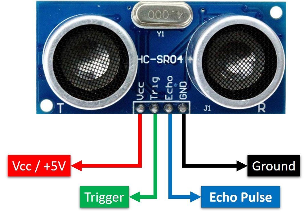
Vcc and Ground are used to power sensor. We should supply 5 volts to the Vcc pin and connect the GND pin with the ground terminal of the power supply.
Trigger: It is an input pin. Trigger pin is used to initiate the ultrasonic sensor to start distance measurement or distance ranging. When users want to get distance measurements from the sensor, we apply a 10µs pulse to this pin.
Echo: This is a pulse output pin. The echo pin produces a pulse as an output. The width of pulse or on-time of the pulse depends on the distance between the ultrasonic sensor and the obstacle which is placed in front of the HC-SR04 sensor. In idle conditions, this pin remains at an active low level.
Further details on ultrasonic sensor working are provided in the next section.
How HC-SR04 Sensor Works?
HC-SR04 ultrasonic sensor measures distance by using inaudible ultrasonic sound waves of 40KHz frequency. Like sound waves, ultrasonic waves travel through the air and if there is any obstacle in front of them, they reflect according to their angle of incidence. Moreover, if an object is placed parallel to an ultrasonic transmitter, ultrasonic waves reflect exactly at an angle of 180 degrees. Therefore, for distance measurement with HC-SR05 sensor, we place the object under test exactly in a parallel position with an ultrasonic sensor as shown in the figure below.
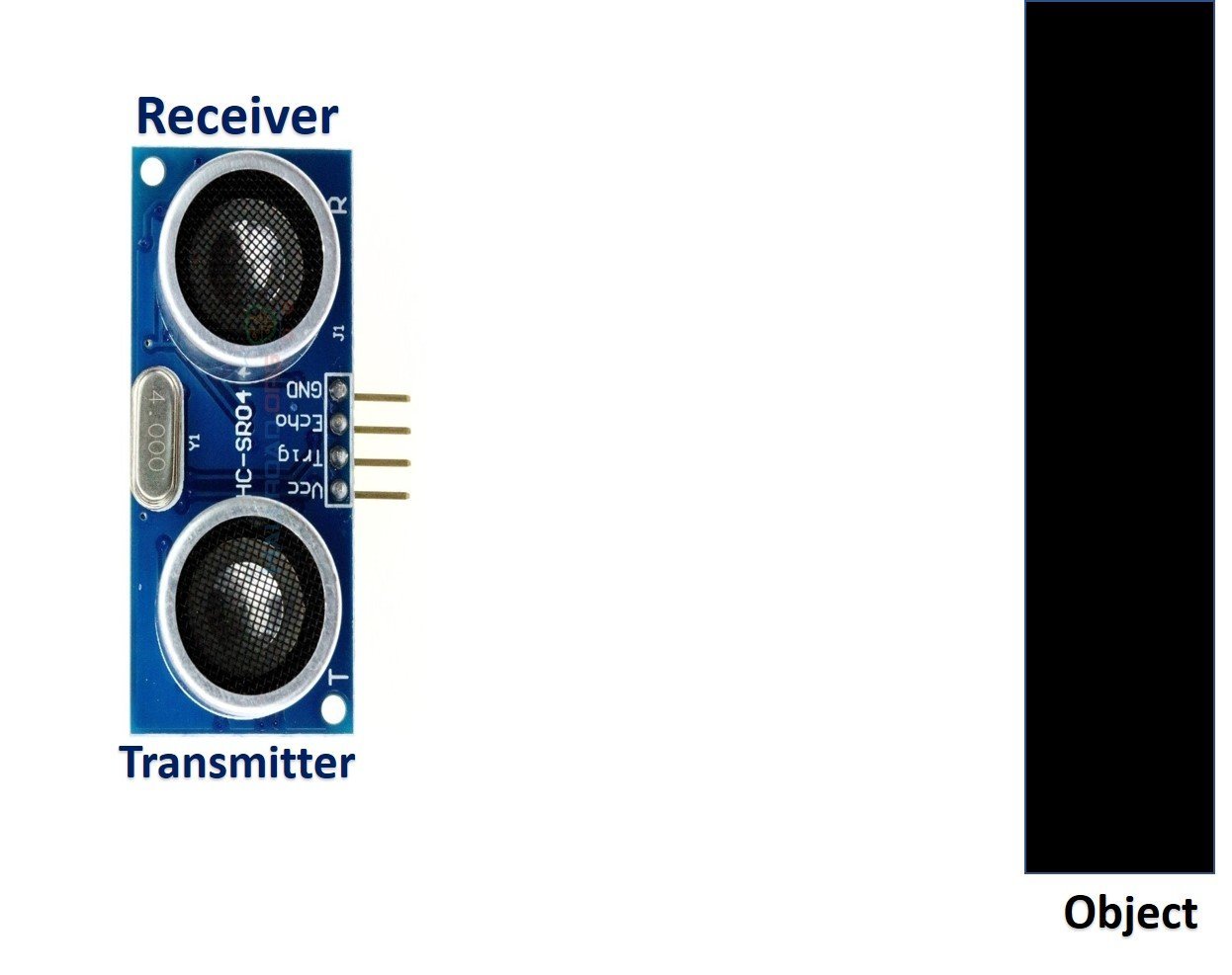
HC-SR05 ultrasonic sensor consists of two basic modules such as ultrasonic transmitter and ultrasonic receiver module. The transmitter circuit converts an electrical signal into a 40KHz burst of 8 sonar wave pulses. The input electrical signal to the transmitter circuit is 10µs pulse input to the trigger pin of the HC-SR04 sensor. As we mentioned earlier, we apply this trigger input signal through ESP32 or any microcontroller. On the other hand, the ultrasonic receiver circuit listens to these ultrasonic waves which are produced by the transmitter circuit.
Measure HC-SR04 Echo Pulse Time with ESP32
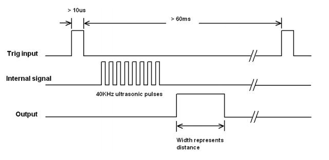
- To start ranging with HC-SR04, first, we apply 10µs pulse to the trigger pin of the HC-SR04 sensor from the ESP32 digital output pin.
- As soon as 10µs input trigger signal becomes active low, the transmitter circuit produces a burst of 8 ultrasonic sonar pulses. At the same time, the Echo pin also makes a transition from a logic low level to a logic high level.
- When the Echo pin goes high, We start to measure time with the ESP32 duration measurement function.
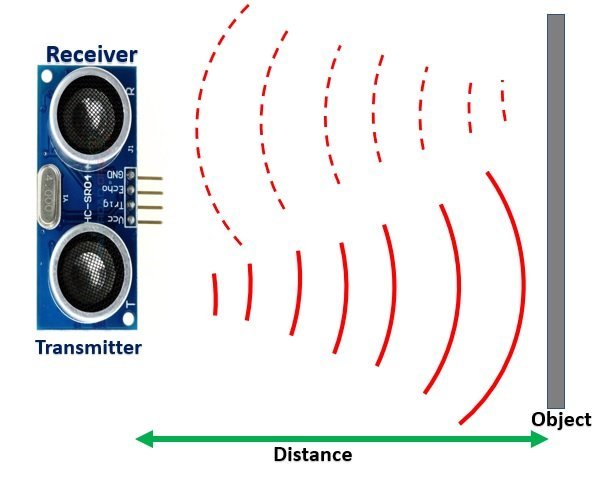
- These waves travel through the air and if there is any object placed in parallel to the sensor, these waves reflect back after a collision with the object.
- As soon as the ultrasonic waves received by the receiver circuit after striking with an object, the echo pin goes low. ESP32 detects this transition of echo output signal from active high to an active low level and stops the measurement.
In short, by measuring the on-time of the Echo output pulse signal, we can measure the distance. The following figure illustrates the echo output signal with respect input trigger signal and 8 sonar pulses.
The duration for which the echo output signal remains high depends on the distance between the ultrasonic sensor and the object which we place in front of the sensor. Higher is the distance, the higher the time sonar waves will take to reach back to the ultrasonic receiver circuit. Because ultrasonic waves travel through the air with the speed of sound and speed remains constant.
How to Convert Time Duration into Distance
In the next section, we will see how to measure pulse duration using ESP32. Let’s assume that we have measured the output pulse on time (t) with ESP32. Now the question is how to convert this measured time into distance.
Well, this is the most obvious part of this tutorial. In high school, we all study a well-known distance-time equation that is S = vt. We can convert the pulse duration (t) into the distance (S) using this equation.
Distance (S) = Speed (v) * t //distance in metersHere v is the speed of ultrasonic waves in air. The speed of ultrasonic waves in air is equal to the speed of sound which is 340 m/s (meter per second).
The above equation will give distance output in units of meter. But, if you want the distance in centimeter units, multiply 340 with 100. Hence, the above equation becomes:
S = 34000 * t // distance in cmThe time given in the above formula should also be divided by two. Because ultrasonic waves travel from the transmitter to the obstacle and then reflect back to the receiver circuit by traveling the same distance. We want to find the distance between HC-SR04 and the object only. Therefore, the formula to calculate distance becomes :
S = 17000 * t // distance in cmHow to Interface HC-SR04 Ultrasonic sensor with ESP32
Until now we have seen the working of the ultrasonic sensor and the pin details. Now we know that to interface an HC-SR04 sensor with ESP32, we need four pins out of which two are power supply pins and two are digital input output pins. One GPIO pin of the ESP32 will be used as a digital output pin to provide a trigger signal to the ultrasonic sensor. Similarly, one GPIO pin will be used as a digital input pin to capture echo output signal of output sensor.
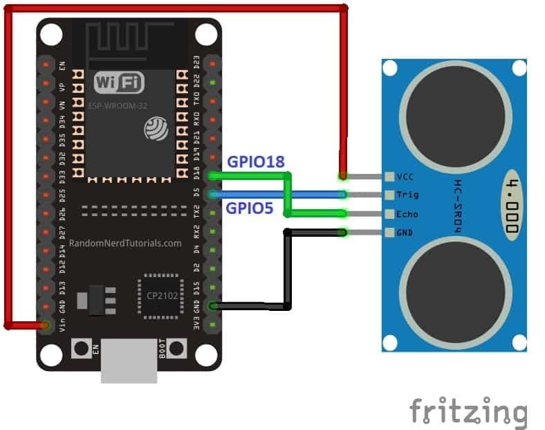
Now make the connection of the ESP32 with the HC-SR04 sensor according to this connection diagram. In this schematic diagram, we use the GPIO5 pin of ESP32 to provide a trigger signal and GPIO18 to capture the echo output pulse.
| HC-SR04 | ESP32 |
| VCC | Vin |
| GND | GND |
| Trigger | GPIO5 |
| Echo | GPIO18 |
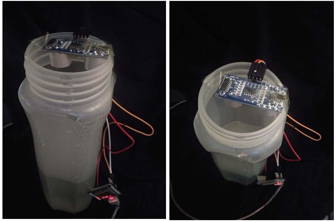
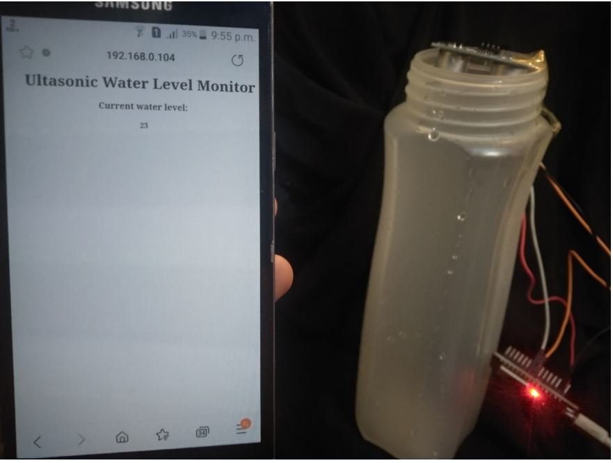
We will set up the ultrasonic sensor on top of a container that will carry the water. This way we will be able to determine the water level by obtaining the distance (cm) from the sensor sending it over to the ESP32 water level monitor web server.
This is how the setup looks like:
You may like to read:
- MicroPython HC-SR04 Ultrasonic Sensor with ESP32 and ESP8266
- HC-SR04 Ultrasonic Sensor with ESP32 – Measure Distance
Setting up Arduino IDE
We will use Arduino IDE to program our ESP32 development board. Thus, you should have the latest version of Arduino IDE. Additionally, you also need to install the plugin for the respective board which you will use.
If your IDE does not have the plugin installed you can visit the link below:
Arduino Sketch ESP32 Water Level Monitoring Web Server
Open your Arduino IDE and go to File > New to open a new file.
Copy the code given below in that file. You will have to replace the network credentials in order to successfully connect to your local WiFi.
#include <WiFi.h>
#include <WiFiClient.h>
#include <WebServer.h>

int trigger_pin = 5;
int echo_pin   = 18;

// Replace with your network credentials
const char* ssid = "MASTERS";
const char* password = "english123";

WebServer server(80);

String page = "";
int distance_cm;

void setup() {
  Serial.begin(115200);
  pinMode(trigger_pin, OUTPUT);
  pinMode(echo_pin, INPUT);
  delay(1000);

  WiFi.begin(ssid, password);
  Serial.println("");
  while (WiFi.status() != WL_CONNECTED) {
    delay(500);
    Serial.print(".");
  }
  Serial.println("");
  Serial.print("IP address: ");
  Serial.println(WiFi.localIP());

  server.on("/", []() {
    page = "<head><meta http-equiv=\"refresh\" content=\"3\"></head><center><h1>Ultasonic Water Level Monitor</h1><h3>Current water level:</h3> <h4>" + String(distance_cm) + "</h4></center>";
    server.send(200, "text/html", page);
  });
  server.begin();
  Serial.println("Web server started!");
}

void loop() {
  digitalWrite(trigger_pin, LOW);
  delayMicroseconds(2);
  digitalWrite(trigger_pin, HIGH);
  delayMicroseconds(10);
  digitalWrite(trigger_pin, LOW);
  long duration = pulseIn(echo_pin, HIGH);
  distance_cm = (duration / 2) / 29.09;
  Serial.println(distance_cm);
  server.handleClient();
  delay(3000);
}
How the Code Works?
Firstly, we will include the necessary libraries. As we have to connect our ESP32 to a wireless network, we need WiFi.h library for that purpose. The WebServer.h will be required to build the web server.
#include <WiFi.h>
#include <WiFiClient.h>
#include <WebServer.h>
Next we will define the names of ESP32 pins that we have connected with the Trigger and Echo pins of the sensor. The following line defines that GPIO5 and GPIO18 pins of ESP32 are used to control trigger and echo pins of the HC-SR04 sensor respectively.
int trigger_pin = 5;
int echo_pin   = 18;
Next, we will create two global variables, one for the SSID and another for the password. These will hold our network credentials which will be used to connect to our wireless router. Replace both of them with your credentials to ensure a successful connection.
// Replace with your network credentials
const char* ssid = "YOUR_SSID";
const char* password = "YOUR_PASSWORD";
The WebServer object will be used to set up the ESP32 web server. We will pass the default HTTP port which is 80, as the input to the constructor. This will be the port where the server will listen to the requests.
WebServer server(80);The integer variable ‘distance_cm’ will hold the value for distance in cm.
int distance_cm;setup()
Inside the setup() function we will open the serial communication at a baud rate of 115200.
Serial.begin(115200);Also, initialize the trigger_pin as a digital output pin and echo_pin as a digital input pin using the pinMode() function.
  pinMode(trigger_pin, OUTPUT);
  pinMode(echo_pin, INPUT);
The following section of code will connect our ESP32 board with the local network whose network credentials we already specified above. After the connection will be established, the IP address of the ESP32 board will get printed on the serial monitor. This will help us to make a request to the server.
 WiFi.begin(ssid, password);
  Serial.println("");
  while (WiFi.status() != WL_CONNECTED) {
    delay(500);
    Serial.print(".");
  }
  Serial.println("");
  Serial.print("IP address: ");
  Serial.println(WiFi.localIP());
The following lines create the HTML web server and start it. Using on() on our our server object we will handle the / URL. The HTML page will be built with three headings showing ‘Ultrasonic Water Level Monitor,’ ‘Current Water Level’, and the distance in cm. Additionally, the web page will automatically refresh after every 3 seconds to show the current reading.
Also, the send() method will be used to return the response. It takes in three parameters. The first parameter is the response code which we will specify as 200. It is the HTTP response code for ok. The second parameter is the content type of the response which we will specify as “text/html” and the third parameter is the actual message which we will be sent as the HTTP response.
To start the server, we will call begin() on our server object.
 server.on("/", []() {
    page = "<head><meta http-equiv=\"refresh\" content=\"3\"></head><center><h1>Ultasonic Water Level Monitor</h1><h3>Current water level:</h3> <h4>" + String(distance_cm) + "</h4></center>";
    server.send(200, "text/html", page);
  });
  server.begin();
  Serial.println("Web server started!");
loop()
Inside the loop() function, we will first provide a 10µs pulse to the trigger pin. This is to enable the ranging of data from the HC-SR04 sensor. It will initiate the distance sample taking process.
  digitalWrite(trigger_pin, LOW);
  delayMicroseconds(2);
  digitalWrite(trigger_pin, HIGH);
  delayMicroseconds(10);
  digitalWrite(trigger_pin, LOW);
As soon as we apply a 10µs pulse to the ultrasonic sensor, in response, it produces 40KHz sonar waves and raises the Echo output signal to an active high state. The echo output signal remains active high until these sonar waves reflect back to the ultrasonic transmitter. As soon as, receiver circuit receives these waves, the echo output signal goes to an active low level.
We measure the time for which the output signal remains in an active high state using the pulseIn() function. Pass the echo_pin as the first parameter and its state ‘HIGH’ as the second parameter. This time we will save in the variable ‘duration.’
long duration = pulseIn(echo_pin, HIGH);The pulseIn() function is used to measure the pulse duration and it returns the time duration output in microseconds. But the formula of the distance-time relationship that we derived above works if both speed and time have the same units in terms of time such as seconds, microseconds, or milliseconds. In this equation, the unit for speed is centimeters per second.
S = 17000 * t
To convert speed into centimeter per microsecond, divide this equation with 10^-6. Now units of speed and time both are compatible with each other.
S = 0.017* t
Then we will calculate the distance in cm using the calculation given below. This will be saved in the variable ‘distance_cm’ that we previously defined.
distance_cm = (duration / 2) / 29.09;This value gets printed in the serial monitor and sent to the ESP32 web server as well.
 Serial.println(distance_cm);
  server.handleClient();
  delay(3000);
IoT based Water Level Monitoring Demonstration
Make sure you choose the correct board and COM port before uploading your code to the board. Go to Tools > Board and select ESP32 Dev Module.

Next, go to Tools > Port and select the appropriate port through which your board is connected.

Click on the upload button to upload the code into the ESP32 development board.
After you have uploaded your code to the development board, press its ENABLE button.

In your Arduino IDE, open up the serial monitor and you will be able to see the IP address of your ESP32 module as well as the distance readings.

Type this IP address in a new web browser and press enter. The following web page will open up.
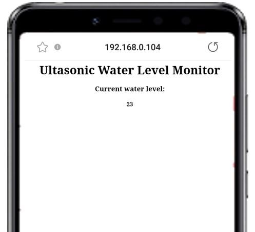
You can view the current water level reading. It is 23 cm right now because the container is empty and 23 cm is the total length of the container.
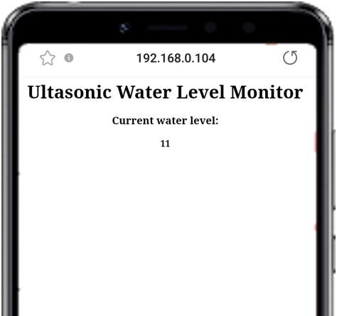
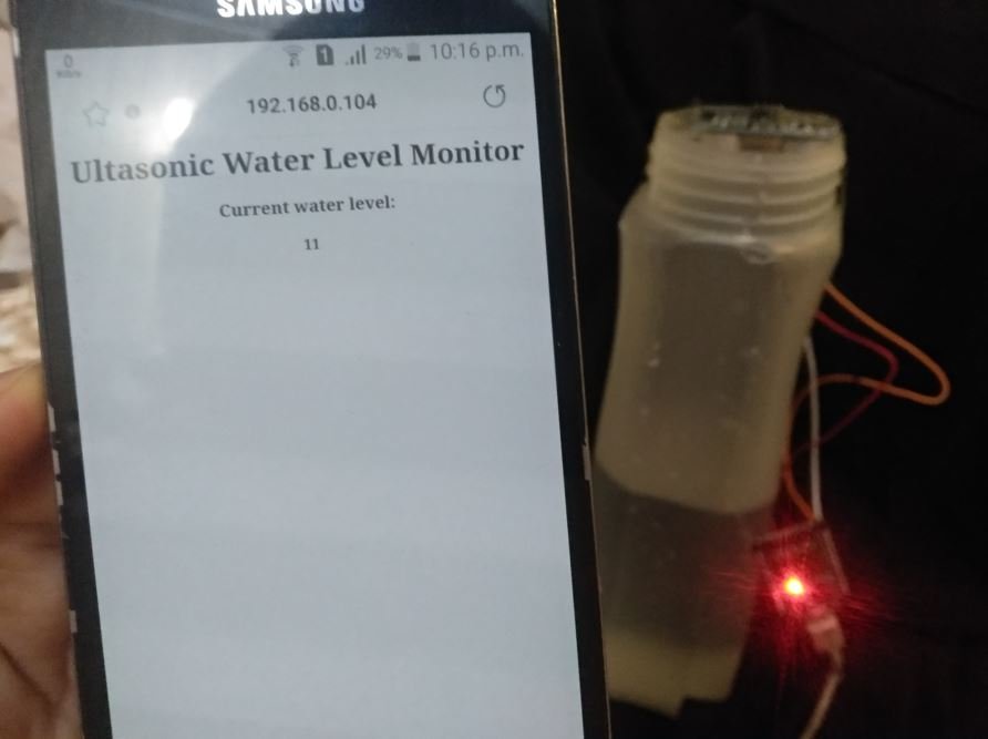
Now start pouring water in the container and the value will start to decrease. At midlevel the value is approximately 11 cm.
Likewise, as the water level increases the distance (cm) decreases.
Watch the video demonstration below:
You may also like to read:
- ESP32 Data Logging to Firebase Realtime Database
- IoT Based Fire Detection using ESP32 and Flame Sensor with Email Alert
- ESP32 Fall Detection using MPU6050 with Email Alerts
- IoT Sound Pollution Monitoring System using ESP32 – Decibel Meter
- ESP32 Multiple Sliders WebSocket Web Server – PWM Control LEDs Brightness
- IoT Based Analog and Digital Clock using OLED and ESP32/ESP8266
Excelente e funcional. Parabens!