In this ESP32 web server project, we will learn how to build an ESP32 PWM WebSocket web server that will control the brightness of multiple LEDs connected to the ESP32 GPIO pins. This will be achieved through multiple HTML sliders that we will add to the web server page. The sliders will be moved to set the slider values. In response, these slider values will set the duty cycle of the PWM signal generated by ESP32 for each LED pin. In short, this variable duty cycle PWM will control the LED brightness. Each slider will be associated with an LED GPIO pin that will be responsible for changing its brightness. However, you can also use a DC motor and a stepper motor to control their speed instead of an LED.
Additionally, we will build our ESP32 web server using the WebSocket protocol. Through WebSocket communication protocol, several clients will be connected to the server concurrently without blocking each other. We will see that, unlike HTTP, a WebSocket server updates the web page to all clients automatically.
Moreover, to make our ESP32 multiple sliders web server project more convenient and practical we will use the feature of ESP32 SPI flash file system (SPIFFS). We will save the HTML, CSS and JavaScript files on the ESP32 SPIFFS that will be used to build the web server. We can use SPIFFS to store files in SPI flash without having to use any external memory with our ESP module.
Recommended Components
The following components are used in this project or are helpful for building it with the ESP32.
| Component | How it’s used in this project | Buy on Amazon |
|---|---|---|
| ESP32 Development Board (DevKit V1) | The main controller that runs the project code and connects to the components. | Check Price |
| Micro USB Cable | Connects the ESP32 to your computer for programming and power. | Check Price |
| Breadboard | Lets you build the circuit and wire up parts without soldering. | Check Price |
| Jumper Wires | Make the connections between the ESP32 and the components on the breadboard. | Check Price |
| 5mm LED | The LED whose brightness is controlled by the ESP32 PWM signal. | Check Price |
| Resistor Kit (220 Ω / 4.7k) | Current-limiting resistors for the LEDs and pull-ups in the circuit. | Check Price |
As an Amazon Associate we earn from qualifying purchases. Prices and availability are accurate as of the date/time indicated and are subject to change.
Points to Note
- In a previous article, we also built an ESP32/ESP8266 slider web server to control LED brightness. However, this guide controlled a single LED thus the web server consisted of a single slider. Additionally, we used HTTP requests to set up the web server. This time we will take that project a step ahead and control three LEDs through their corresponding sliders and use WebSocket protocol instead. This way, multiple clients will automatically get updated with the current states of the sliders
ESP32 PWM Slider Web Server – Control LED Brightness
- Moreover, you can also go through the recommended reading given below. It is a useful guide in which we used ESP32 PWM to control the brightness of an LED using Arduino IDE. We will be using a similar approach in this guide as well but will include a web server with sliders instead to control the brightness.
Recommended Reading: ESP32 PWM with Arduino IDE – LED fading example
ESP32 Multiple Sliders WebSocket Web Server Project Overview
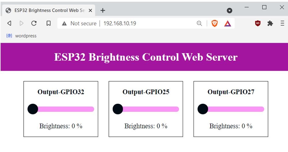
We will create a web server based on the WebSocket protocol consisting of three sliders each controlling the brightness of an LED associated with it. We aim to build a webpage through which the user will move the sliders to change the brightness of the LEDs connected to the output GPIO pins of the ESP32 board. The web server will consist of a title: “ESP32 Brightness Control Web Server,” and three cards for each slider information. Each card will consist of a paragraph to show the title specifying the output GPIO it controls, a slider to set the value that will alter the duty cycle for PWM to set the brightness of the LED and the brightness value in percentage.

Our web server consists of three sliders each associated with a GPIO pin. Slider 1 controls the brightness of the LED connected with GPIO32. Slider 2 controls the brightness of the LED connected with GPIO25. Likewise, Slider 3 controls the brightness of the LED connected with GPIO27.
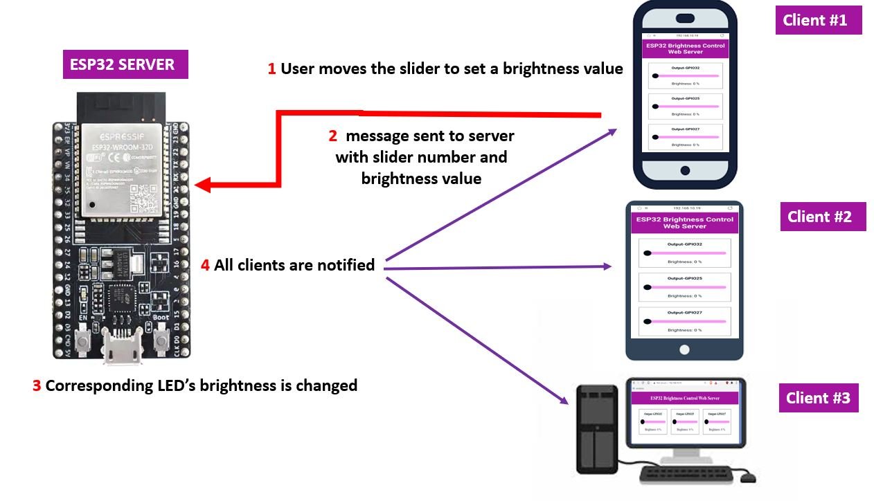
We will move the slider to set the brightness value which corresponds to the duty cycle in percentage. This will generate a request with the slider number and set value to our ESP32 board. Whenever the slider will be moved, the brightness will be changed, it will automatically get updated on the webpage immediately. This will occur for all the clients who will be connected with the ESP32 (server).
Working Process
- First, the user will move the slider to set a brightness value. The slider can take a minimum value of 0 (no PWM) and a maximum of 100% (duty cycle 100%) that shows the highest brightness. The brightness value indicates the duty cycle percentage.
- The web server will send the message request message through the WebSocket communication protocol. It will consist of the slider number and the brightness value. For example if slider 2 (associated with output GPIO25) was moved and set to a brightness value of 20%, “2s20” message will be sent.
- Our ESP32 board will receive this request and set the corresponding LED to the set brightness. In this case the LED connected with GPIO25 will turn ON at a brightness level of 20%.
- Next, the ESP32 will send the new state of the web page to all the connected clients with the help of WebSocket.
- Immediately all the clients will receive the new message and their respective web pages will update to the new current state.
Required Components
- ESP32 development board
- Three 5mm LEDs
- Three 220ohm resistors
- Breadboard
- Connecting Wires
ESP32 Multiple Sliders WebSocket Web Server Schematic Diagram
Follow the schematic diagram below to assemble your circuit.
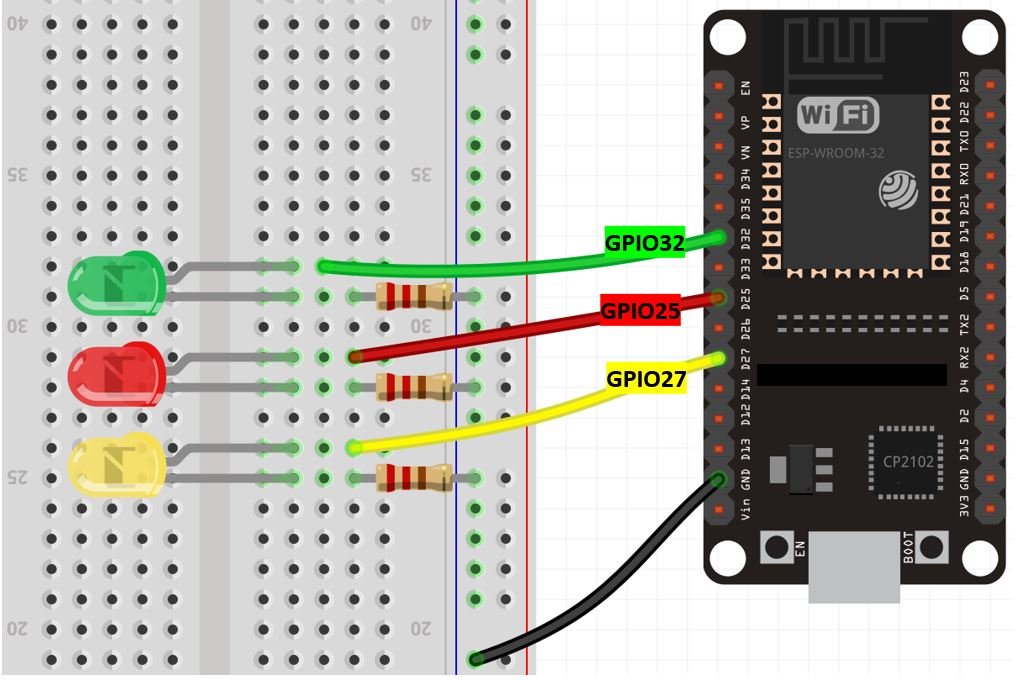
We have used three LEDs and connected their anode pin with three different GPIO pins. Later on, in the program code, we will configure these GPIO pins as output pins. You can use any appropriate output GPIO pins. The cathode pins are grounded through the 220ohm resistors.
Setting up Arduino IDE for ESP32 Multiple Sliders WebSocket Web Server
We will use Arduino IDE to program our ESP32 development board. Thus, you should have the latest version of Arduino IDE. Additionally, you also need to install the ESP32 plugin. You can visit the link shown below to have a look.
Installing ESP32 library in Arduino IDE and upload code.
Also, you will have to download and install the ESP32 Filesystem Uploader Plugin in your Arduino IDE so that you are able to upload the SPIFFS files on your ESP32 board. If you haven’t, you can follow this tutorial:
Install ESP32 Filesystem Uploader in Arduino IDE – SPIFFS
Installing Libraries
We will need three libraries to build our ESP32 multiple sliders web server with WebSocket protocol.
- ESPAsyncWebServer library
- AsyncTCP library
- Arduino_JSON library
The ESPAsyncWebServer library will help us in creating our web server easily. With this library, we will set up an asynchronous web server. AsyncTCP library will also be incorporated as it a dependency for the ESPAsyncWebServer library. These two libraries are not available in the Arduino library manager. Therefore, we will have to download and load them on our ESP32 board ourselves.
- To install the ESPAsyncWebServer library for free, click here to download. You will download the library as a .zip folder which you will extract and rename as ‘ESPAsyncWebServer.’ Then, transfer this folder to the installation library folder in your Arduino IDE.
- To install the Async TCP library for free, click here to download. You will download the library as a .zip folder which you will extract and rename as ‘AsyncTCP.’ Then, transfer this folder to the installation library folder in your Arduino IDE.
Likewise, you can also go to Sketch > Include Library > Add .zip Library inside the IDE to add the libraries as well.
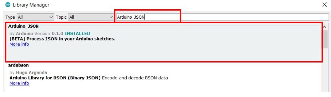
To install Arduino_JSON library, we will use the Arduino Library Manager. Open your Arduino IDE and go to Sketch > Include Libraries > Manage Libraries. Type ‘Arduino_JSON’ the search bar and install the latest version.
After installation of the libraries, restart your IDE.
Creating Files for SPIFFS
In most of our web server projects with ESP32, we have included HTML and CSS files inside our Arduino sketch. We save these HTML documents inside Arduino sketch by converting them into strings. Whenever a web client makes an HTTTP request, we send this string as a response which is basically a web page. On the contrary, with SPIFFS, we can save HTML, CSS, and JavaScript files in ESP32 flash file system. Whenever a web client makes a request, we can serve these files directly from SPIFFS. It is convenient to have separate HTML, CSS and JavaScript files saved on the ESP32 SPIFFS. All of these three files will later be linked together. The SPIFFS will help us access the flash memory of the ESP32 core. We will store our files in the flash memory of the ESP32 board and serve them in our web server.
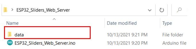
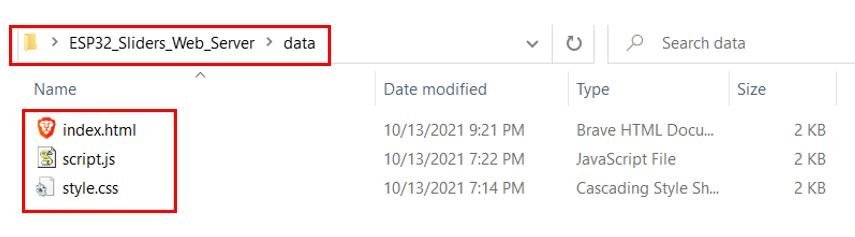
To build an ESP32 web server using SPIFFS, we will create three different files: HTML, CSS, JavaScript and Arduino sketch and organize them in a project folder like shown below:
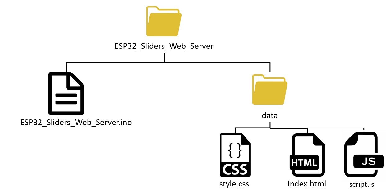
Note: You should place HTML and CSS files inside the data folder. Otherwise, SPIFFS library will not be able to read these files.
Creating HTML file
Inside our HTML file, we will specify the title of the web page and the three cards. Each card will contain a paragraph to show the title specifying the output GPIO the slider controls, a slider to set the value that will alter the duty cycle for PWM to set the brightness of the LED and the brightness value in percentage.
Now, create an index.html file and replicate the code given below in that file.
<!DOCTYPE html>
<html>
<head>
<title>ESP32 Brightness Control Web Server</title>
<meta name="viewport" content="width=device-width, initial-scale=1">
<link rel="icon" type="image/png" href="favicon.png">
<link rel="stylesheet" type="text/css" href="style.css">
</head>
<body>
<div class="topnav">
<h1>ESP32 Brightness Control Web Server</h1>
</div>
<div class="content">
<div class="card-grid">
<div class="card">
<p class="card-title">Output-GPIO32</p>
<p class="switch">
<input type="range" onchange="updateSliderPWM(this)" id="slider1" min="0" max="100" step="1" value ="0" class="slider">

</p>
<p class="state">Brightness: <span id="slider_value1"></span> %</p>
</div>
<div class="card">
<p class="card-title">Output-GPIO25</p>
<p class="switch">
<input type="range" onchange="updateSliderPWM(this)" id="slider2" min="0" max="100" step="1" value ="0" class="slider">
</p>
<p class="state">Brightness: <span id="slider_value2"></span> %</p>
</div>
<div class="card">
<p class="card-title">Output-GPIO27</p>
<p class="switch">
<input type="range" onchange="updateSliderPWM(this)" id="slider3" min="0" max="100" step="1" value ="0" class="slider">
</p>
<p class="state">Brightness: <span id="slider_value3"></span> %</p>
</div>
</div>
</div>
http://script.js
</body>
</html>Building the Web page
We will start with the title of the web page. The tag will indicate the beginning of the title and the </tile> tag will indicate the ending. In between these tags, we will specify “ESP32 Brightness Control Web Server” which will be displayed in the browser’s title bar </p>.
<title>ESP32 Brightness Control Web Server</title>Next, we will create a meta tag to make sure our web server is available for all browsers e.g., smartphones, laptops, computers etc.
<meta name="viewport" content="width=device-width, initial-scale=1">Between the <head></head> tags, we will reference the CSS file as we’ll be creating different files for both HTML and CSS by using the <link> tag. This tag will be used so that we can link with an external style sheet which we will specify as a CSS file. It will consist of three attributes. The first one is rel which shows the relationship between the current file and the one which is being linked.
We will specify “stylesheet” which will change the visuals of the web page. The second attribute is type which we will specify as “text/css” as we will be using the CSS file for styling purpose. The third attribute is href and it will specify the location of the linked file. Both of the files (HTML & CSS) will be saved in the same folder (data) so we will just specify the name of the CSS file that is “style.css.”
<link rel="stylesheet" type="text/css" href="style.css">Inside the HTML web page body, we will include the heading and the three cards. This will go inside the <body></body> tags which will mark the beginning and the ending of the script. We will include the heading of our webpage inside the <h1></h1> tags and it will be the same as that of the web browser title i.e. “ESP32 Brightness Control Web Server”.
<h1>ESP32 Brightness Control Web Server</h1>Now we will create the first card. We will include a paragraph for the card title. This will be found above the slider. We have specified it as “Output-GPIO32.” This is the GPIO pin that this particular slider will control.
<p class="card-title">Output-GPIO32</p>Creating the Slider
<p class="switch">
<input type="range" onchange="updateSliderPWM(this)" id="slider1" min="0" max="100" step="1" value ="0" class="slider">
</p>Next, we will have another paragraph in which we will create the slider. As you may notice the slider represents an input type in HTML. Thus, we have specified it inside the tag where the user will be able to enter some type of data. Further, the slider is identified as input field type ‘range’. This represents the range of the data that will be associated with the slider. We will call the updateSliderPWM() function and specify it in the onchange property. This will occur when the user will move the slider. Next in the ‘id’ attribute, we will specify ‘slider1’ as the unique id for our slider.
We will use the following properties to specify the range in our slider:
- min: This corresponds to the minimum value of the data. We are specifying it as 0.
- max: This corresponds to the maximum value of the data. We are specifying it as 100.
- value: This corresponds to the slider value which we have specified as 0.
- step: This corresponds to the interval between consecutive numbers. We have set it to 1. Thus values can be incremented/decremented by ±1.
Thus the range of values which is the PWM slider can take are from 0-100.
Next, we have another paragraph which shows the brightness value with the span id “slider_value1”. This will refer to the current slider value for the slider1.
<p class="state">Brightness: <span id="slider_value1"></span> %</p>Creating Multiple Sliders
Now we will create two more sliders so that we have a total of three sliders in our web server. The following lines of code will create the second slider. It controls the LED connected with GPIO25. It has the span id “slider_value2”. This will refer to the current slider value for the slider2.
. First, however, you need to consider that you need a unique id for each slider and slider value. In our case, we have three sliders with the following ids: slider1, slider2, slider3, and three placeholders for the slider value with the following ids: sliderValue1, sliderValue2, sliderValue3.
<div class="card">
<p class="card-title">Output-GPIO25</p>
<p class="switch">
<input type="range" onchange="updateSliderPWM(this)" id="slider2" min="0" max="100" step="1" value ="0" class="slider">
</p>
<p class="state">Brightness: <span id="slider_value2"></span> %</p>
</div>Likewise, the following lines of code will create the third slider. It controls the LED connected with GPIO27. It has the span id “slider_value3”. This will refer to the current slider value for the slider3.
<div class="card">
<p class="card-title">Output-GPIO27</p>
<p class="switch">
<input type="range" onchange="updateSliderPWM(this)" id="slider3" min="0" max="100" step="1" value ="0" class="slider">
</p>
<p class="state">Brightness: <span id="slider_value3"></span> %</p>
</div>Creating CSS File
Next, create another file “style.css” in the data folder and copy the code given below in that file. CSS is used to give styles to a web page.
html {
    font-family:New Times Roman;
    display: inline-block;
    text-align: center;
  }
  h1 {
    font-size: 2.0rem;
    color: white;
  }
  p {
    font-size: 1.5rem;
  }
  .topnav {
    overflow: hidden;
    background-color: #a3159e;
  }
  body {
    margin: 0;
  }
  .content {
    padding: 30px;
  }
  .card-grid {
    max-width: 700px;
    margin: 0 auto;
    display: grid;
    grid-gap: 2rem;
    grid-template-columns: repeat(auto-fit, minmax(200px, 1fr));
  }
  .card {
    background-color: white;
    outline-color: black;
    outline: 1px solid;
  }
  .card-title {
    font-size: 1.2rem;
    font-weight: bold;
    color:#010b14;
  }
  .state {
    font-size: 1.2rem;
    color:#010b14;
  }
  .slider {
    -webkit-appearance: none;
    margin: 0 auto;
    width: 100%;
    height: 15px;
    border-radius: 10px;
    background: #fa96f5;
    outline: none;
  }
  .slider::-webkit-slider-thumb {
    -webkit-appearance: none;
    appearance: none;
    width: 30px;
    height: 30px;
    border-radius: 50%;
    background: #010b14;
    cursor: pointer;
  }
  .slider::-moz-range-thumb {
    width: 30px;
    height: 30px;
    border-radius: 50% ;
    background:#010b14;
    cursor: pointer;
  }
  .switch {
    padding-left: 5%;
    padding-right: 5%;
  }
To add CSS files in head tags, we will use <style></style> tags to mark the beginning and the end. We will set the display text to font type Times New Roman and align it in the centre of the webpage. The font size, colour and positioning of the heading, paragraph, card and the slider will also be set. Additionally, we will also add the styling for the slider that we will display on our web server. The track of the slider will be pink in colour with a black thumb.
Creating JavaScript File
Now create another file in the data folder and name it ‘script.js.’ This is the JavaScript file responsible for handling the web socket communication.
var gateway = `ws://${window.location.hostname}/ws`;
var websocket;
window.addEventListener('load', onload);

function onload(event) {
    initWebSocket();
}

function getValues(){
    websocket.send("getValues");
}

function initWebSocket() {
    console.log('Trying to open a WebSocket connection…');
    websocket = new WebSocket(gateway);
    websocket.onopen = onOpen;
    websocket.onclose = onClose;
    websocket.onmessage = onMessage;
}

function onOpen(event) {
    console.log('Connection opened');
    getValues();
}

function onClose(event) {
    console.log('Connection closed');
    setTimeout(initWebSocket, 2000);
}

function updateSliderPWM(element) {
    var slider_number = element.id.charAt(element.id.length-1);
    var slider_value = document.getElementById(element.id).value;
    document.getElementById("slider_value"+slider_number).innerHTML = slider_value;
    console.log(slider_value);
    websocket.send(slider_number+"s"+slider_value.toString());
}

function onMessage(event) {
    console.log(event.data);
    var myObj = JSON.parse(event.data);
    var keys = Object.keys(myObj);

    for (var i = 0; i < keys.length; i++){
        var key = keys[i];
        document.getElementById(key).innerHTML = myObj[key];
        document.getElementById("slider"+ (i+1).toString()).value = myObj[key];
    }
}
Inside the <script></script> tags, we will include the JavaScript to handle the WebSocket. Data exchange as well as initiating the two-way connection between the client-server will be accomplished through this script when the webpage will be formed.
Firstly, we will create a gateway that will act as the entrance to the WebSocket interface. We will specify the webserver IP address (window.location.hostname) for the gateway.
var gateway = `ws://${window.location.hostname}/ws`;Then we will create a new variable of type ‘var’ named ‘websocket’. Through the window.addwindowListener()function we will call the onload function. This will occur when the webserver will be loaded.
var websocket;
window.addEventListener('load', onload);
Next, we will define the onload() function. This takes in the parameter ‘event’ and calls the initWebSocket() function. The initWebsocket() function will be used to initialize the WebSocket.
function onload(event) {
    initWebSocket();
}
The getValues() function takes in no parameter. It is responsible for obtaining the current slider values.
function getValues(){
    websocket.send("getValues");
}
Initializing WebSocket
For the initWebSocket() function, we will use it to initialize the WebSocket connection. Three different callback functions will also be included to cater when a message will be received or the connection is opened/closed. Next, we will define each callback function separately.
function initWebSocket() {
    console.log('Trying to open a WebSocket connection…');
    websocket = new WebSocket(gateway);
    websocket.onopen = onOpen;
    websocket.onclose = onClose;
    websocket.onmessage = onMessage;
}
Now, we will define the onOpen() function in which ‘event’ is passed as an argument . When the WebSocket connection is opened, the console.log() function is called. This will write the message which is passed as an argument into the browser console. In our case, the message is ‘Connection opened.’ Additionally, the getVaules() function will also be called.
function onOpen(event) {
    console.log('Connection opened');
    getValues();
}
For the onClose() function, event will be passed as argument. When the WebSocket connection is closed, console.log() function is called which will log ‘Connection closed’ in the browser log. Additionally, the initWebSocket() function will be called after every 2 seconds to initiate the WebSocket connection.
function onClose(event) {
    console.log('Connection closed');
    setTimeout(initWebSocket, 2000);
}
To update the value of the slider we will call the updateSliderPWM() function. This takes in a single argument called ‘element’. Whenever the user will move the slider on the webpage the following function will do its job. As you can see, the current slider value and slider number is obtained by referring to its ‘id’ This value is then updated to the value saved in the ‘slider_value’ variable. It consists of the slider value and the slider number. This current slider value gets updated in the web server and the brightness is set to the appropriate level.
function updateSliderPWM(element) {
    var slider_number = element.id.charAt(element.id.length-1);
    var slider_value = document.getElementById(element.id).value;
    document.getElementById("slider_value"+slider_number).innerHTML = slider_value;
    console.log(slider_value);
    websocket.send(slider_number+"s"+slider_value.toString());
}
The onMessage() function is called whenever a new message will be received. This function is responsible for updating all the current values on the web server.
function onMessage(event) {
    console.log(event.data);
    var myObj = JSON.parse(event.data);
    var keys = Object.keys(myObj);

    for (var i = 0; i < keys.length; i++){
        var key = keys[i];
        document.getElementById(key).innerHTML = myObj[key];
        document.getElementById("slider"+ (i+1).toString()).value = myObj[key];
    }
}
Arduino Sketch
Now, open your Arduino IDE and go to File > New to open a new file. Copy the code given below in that file and save it as ‘ESP32_Sliders_Web_Server’.
#include <Arduino.h>
#include <WiFi.h>
#include <AsyncTCP.h>
#include <ESPAsyncWebServer.h>
#include "SPIFFS.h"
#include <Arduino_JSON.h>

const char* ssid = "Your_SSID";
const char* password = "Your_Password";


AsyncWebServer server(80);
AsyncWebSocket ws("/ws");

const int led_pin1 = 32;
const int led_pin2 = 25;
const int led_pin3 = 27;

String message = "";
String slider_value1 = "0";
String slider_value2 = "0";
String slider_value3 = "0";

int duty_cycle1;
int duty_cycle2;
int duty_cycle3;

const int frequency = 5000;
const int Led1_channel = 0;
const int Led2_channel = 1;
const int Led3_channel = 2;
const int resolution = 8;

JSONVar slider_values;

String getslider_values(){
  slider_values["slider_value1"] = String(slider_value1);
  slider_values["slider_value2"] = String(slider_value2);
  slider_values["slider_value3"] = String(slider_value3);

  String jsonString = JSON.stringify(slider_values);
  return jsonString;
}


void notifyClients(String slider_values) {
  ws.textAll(slider_values);
}

void handleWebSocketMessage(void *arg, uint8_t *data, size_t len) {
  AwsFrameInfo *info = (AwsFrameInfo*)arg;
  if (info->final && info->index == 0 && info->len == len && info->opcode == WS_TEXT) {
    data[len] = 0;
    message = (char*)data;
    if (message.indexOf("1s") >= 0) {
      slider_value1 = message.substring(2);
      duty_cycle1 = map(slider_value1.toInt(), 0, 100, 0, 255);
      Serial.println(duty_cycle1);
      Serial.print(getslider_values());
      notifyClients(getslider_values());
    }
    if (message.indexOf("2s") >= 0) {
      slider_value2 = message.substring(2);
      duty_cycle2 = map(slider_value2.toInt(), 0, 100, 0, 255);
      Serial.println(duty_cycle2);
      Serial.print(getslider_values());
      notifyClients(getslider_values());
    }
    if (message.indexOf("3s") >= 0) {
      slider_value3 = message.substring(2);
      duty_cycle3 = map(slider_value3.toInt(), 0, 100, 0, 255);
      Serial.println(duty_cycle3);
      Serial.print(getslider_values());
      notifyClients(getslider_values());
    }
    if (strcmp((char*)data, "getValues") == 0) {
      notifyClients(getslider_values());
    }
  }
}
void onEvent(AsyncWebSocket *server, AsyncWebSocketClient *client, AwsEventType type, void *arg, uint8_t *data, size_t len) {
  switch (type) {
    case WS_EVT_CONNECT:
      Serial.printf("WebSocket client #%u connected from %s\n", client->id(), client->remoteIP().toString().c_str());
      break;
    case WS_EVT_DISCONNECT:
      Serial.printf("WebSocket client #%u disconnected\n", client->id());
      break;
    case WS_EVT_DATA:
      handleWebSocketMessage(arg, data, len);
      break;
    case WS_EVT_PONG:
    case WS_EVT_ERROR:
      break;
  }
}

void initWebSocket() {
  ws.onEvent(onEvent);
  server.addHandler(&ws);
}


void setup() {
  Serial.begin(115200);
  pinMode(led_pin1, OUTPUT);
  pinMode(led_pin2, OUTPUT);
  pinMode(led_pin3, OUTPUT);

    if (!SPIFFS.begin()) {
    Serial.println("An error has occurred while mounting SPIFFS");
  }
  else{
   Serial.println("SPIFFS mounted successfully");
  }

  WiFi.mode(WIFI_STA);
  WiFi.begin(ssid, password);
  Serial.print("Connecting to WiFi ..");
  while (WiFi.status() != WL_CONNECTED) {
    Serial.print('.');
    delay(1000);
  }
  Serial.println(WiFi.localIP());

  ledcSetup(Led1_channel, frequency, resolution);
  ledcSetup(Led2_channel, frequency, resolution);
  ledcSetup(Led3_channel, frequency, resolution);

  ledcAttachPin(led_pin1, Led1_channel);
  ledcAttachPin(led_pin2, Led2_channel);
  ledcAttachPin(led_pin3, Led3_channel);

  initWebSocket();

  server.on("/", HTTP_GET, [](AsyncWebServerRequest *request){
    request->send(SPIFFS, "/index.html", "text/html");
  });

  server.serveStatic("/", SPIFFS, "/");
  server.begin();
}

void loop() {
  ledcWrite(Led1_channel, duty_cycle1);
  ledcWrite(Led2_channel, duty_cycle2);
  ledcWrite(Led3_channel, duty_cycle3);

  ws.cleanupClients();
}
How the Code Works?
Firstly, we will include the necessary libraries. As we have to connect our ESP32 to a wireless network, we need WiFi.h library for that purpose. The ESPAsyncWebServer and AsyncTCP libraries are the ones that we recently downloaded and will be required to build the asynchronous web server. Also, the SPIFFS library will allow us to access the flash memory file system of our ESP32 core. Additionally, the Arduino_JSON library will be used as we will use a JSON variable to store the message.
#include <Arduino.h>
#include <WiFi.h>
#include <AsyncTCP.h>
#include <ESPAsyncWebServer.h>
#include "SPIFFS.h"
#include <Arduino_JSON.h>
Next, we will create two global variables, one for the SSIDpassword. These will hold our network credentials which will be used to connect to our wireless router. Replace both of them with your credentials to ensure a successful connection.
const char* ssid = "Your_SSID";
const char* password = "Your_Password";
Creating AsyncWebServer and Socket Objects
The AsyncWebServer object will be used to set up the ESP32 web server. We will pass the default HTTP port which is 80, as the input to the constructor. This will be the port where the server will listen to the requests. We will also create an object for the AsyncWebSocket called ‘ws’. This will be used on the /ws path to handle connections appropriately.
AsyncWebServer server(80);
AsyncWebSocket ws("/ws");
Defining Variables
Then, we will define three variables to save the GPIO pins connected with each of the three LEDs. The first LED is connected with GPIO32. The second LED is connected with GPIO25 and the third LED is connected with GPIO27. You can use any appropriate output GPIO pins.
const int led_pin1 = 32;
const int led_pin2 = 25;
const int led_pin3 = 27;
We will define some string variables that will be used later on in the sketch to hold the message and the slider values. Each slider has its own variable defined namely slider_value1, slider_value2 and slider_value2. We have set them equal to zero. So at first, the web server will display the brightness percentage at 0.
String message = "";
String slider_value1 = "0";
String slider_value2 = "0";
String slider_value3 = "0";
Next we define the PWM parameters for each LED. It includes the frequency of the signal, led channel and resolution. We have set the frequency at 5000 Hz. For defining the PWM channel we can choose between a total of sixteen PWM channels in ESP32. You can use any channel from 0-15. We have set the PWM channel to 0, 1, 2 for three LEDs respectively. Additionally, we have set the PWM resolution to 8 bits as it is the optimal resolution to obtain the maximum frequency. Although you can use resolution between 1-16 bits. As we are using 8-bit resolution, thus the duty cycle value will vary between 0-255 which we will map to 0-100%. Duty cycle defines the width of the signal or ON time of the signal. The duty cycles are also defined as integer variables named: duty_cycle1, duty_cycle2 and duty_cycle3 for each of the LED respectively.
int duty_cycle1;
int duty_cycle2;
int duty_cycle3;

const int frequency = 5000;
const int Led1_channel = 0;
const int Led2_channel = 1;
const int Led3_channel = 2;
const int resolution = 8;
Creating JSON variable
Moreover, we will also create a JSON variable called ‘slider_values’ to store the individual sets of current slider values for each slider.
JSONVar slider_values;getslider_values()
In the getslider_values() function, we will create a JSON string containing the current slider values. We will use the JSON variable ‘slider_values’ and save each of the slider_value1, slider_value2 and slider_value3 in it. ALL three of these will be linked together in the string variable ‘jsonString.’ This function returns that variable when it is called.
String getslider_values(){
  slider_values["slider_value1"] = String(slider_value1);
  slider_values["slider_value2"] = String(slider_value2);
  slider_values["slider_value3"] = String(slider_value3);

  String jsonString = JSON.stringify(slider_values);
  return jsonString;
}
notifyClients()
Through this function, we want to notify all the connected clients of the updated state of the slider values when subjected to a change. We will achieve this through the textAll() method which will send the same string (slider_values) to all the clients on board.
void notifyClients(String slider_values) {
  ws.textAll(slider_values);
}
handleWebSocketMessage()
Next, we will define the handleWebSocketMessage(). This will act as a callback function. When new information is received by our ESP32 through the WebSocket, this callback function will run. It will send the updated slider values to all the connected clients through the notifyClient() function. Inside the notifyClients() function, we will pass the getslider_vlaues() function as a parameter. Additionally, it will also check through an if statement whether the message came from slider1, slider2 or slider3 and then change the duty cycle (duty_cycle1, duty_cycle2 or duty_cycle3) and notify clients accordingly.
void handleWebSocketMessage(void *arg, uint8_t *data, size_t len) {
  AwsFrameInfo *info = (AwsFrameInfo*)arg;
  if (info->final && info->index == 0 && info->len == len && info->opcode == WS_TEXT) {
    data[len] = 0;
    message = (char*)data;
    if (message.indexOf("1s") >= 0) {
      slider_value1 = message.substring(2);
      duty_cycle1 = map(slider_value1.toInt(), 0, 100, 0, 255);
      Serial.println(duty_cycle1);
      Serial.print(getslider_values());
      notifyClients(getslider_values());
    }
    if (message.indexOf("2s") >= 0) {
      slider_value2 = message.substring(2);
      duty_cycle2 = map(slider_value2.toInt(), 0, 100, 0, 255);
      Serial.println(duty_cycle2);
      Serial.print(getslider_values());
      notifyClients(getslider_values());
    }
    if (message.indexOf("3s") >= 0) {
      slider_value3 = message.substring(2);
      duty_cycle3 = map(slider_value3.toInt(), 0, 100, 0, 255);
      Serial.println(duty_cycle3);
      Serial.print(getslider_values());
      notifyClients(getslider_values());
    }
    if (strcmp((char*)data, "getValues") == 0) {
      notifyClients(getslider_values());
    }
  }
}
onEvent()
The following section of code will define the onEvent() function. This will enable an event listener which will handle the Websocket connection properly. There are five different values that the event (type) can take up. These are shown below:
- WS-EVT-CONNECT: when a client will log in
- WS_EVT_DISCONNECT: when the client will log out
- WS_EVT_DATA: when data will be received from the client
- WS_EVT_PONG: when a ping request will come up
- WS_EVT_ERROR: when an error will be received from the client
void onEvent(AsyncWebSocket *server, AsyncWebSocketClient *client, AwsEventType type, void *arg, uint8_t *data, size_t len) {
  switch (type) {
    case WS_EVT_CONNECT:
      Serial.printf("WebSocket client #%u connected from %s\n", client->id(), client->remoteIP().toString().c_str());
      break;
    case WS_EVT_DISCONNECT:
      Serial.printf("WebSocket client #%u disconnected\n", client->id());
      break;
    case WS_EVT_DATA:
      handleWebSocketMessage(arg, data, len);
      break;
    case WS_EVT_PONG:
    case WS_EVT_ERROR:
      break;
  }
}
initWebSocket() for ESP32 side
This function will initialize our WebSocket protocol for the server side.
void initWebSocket() {
  ws.onEvent(onEvent);
  server.addHandler(&ws);
}
setup()
Inside the setup() function, we will open a serial connection at a baud rate of 115200.
Serial.begin(115200);By using the pinMode() function, the led_pin1, led_pin2 and led_pin3 will be configured as output pins.
pinMode(led_pin1, OUTPUT);
pinMode(led_pin2, OUTPUT);
pinMode(led_pin3, OUTPUT);
These lines of code will initialize the SPIFFS.
 if (!SPIFFS.begin()) {
    Serial.println("An error has occurred while mounting SPIFFS");
  }
  else{
   Serial.println("SPIFFS mounted successfully");
  }
The following section of code will connect our ESP32 board with the local network whose network credentials we already specified above. After the connection will be established, the IP address of the ESP32 board will get printed on the serial monitor. This will help us to make a request to the server.
WiFi.mode(WIFI_STA);
  WiFi.begin(ssid, password);
  Serial.print("Connecting to WiFi ..");
  while (WiFi.status() != WL_CONNECTED) {
    Serial.print('.');
    delay(1000);
  }
  Serial.println(WiFi.localIP());
By using ledcSetup(), we will initialize the PWM parameters for the three LEDs. This function takes in three parameters. The channel number, frequency, and the resolution of the PWM channel.
ledcSetup(Led1_channel, frequency, resolution);
ledcSetup(Led2_channel, frequency, resolution);
ledcSetup(Led3_channel, frequency, resolution);
Secondly we will use ledcAttach() to attach the led pins to the respective channels.
ledcAttachPin(led_pin1, Led1_channel);
ledcAttachPin(led_pin2, Led2_channel);
ledcAttachPin(led_pin3, Led3_channel);
Also, we will call the initWebSocket() to initialize the WebSocket communication protocol.
initWebSocket();We will use the on() method on the server object to listen to the incoming HTTP requests and execute functions accordingly. The send() method uses to return the HTTP response. The index.html file will send to the client, whenever the server will receive a request on the “/” URL.
  server.on("/", HTTP_GET, [](AsyncWebServerRequest *request){
    request->send(SPIFFS, "/index.html", "text/html");
  });

  server.serveStatic("/", SPIFFS, "/");
To start the server, we will call the begin() on our server object.
server.begin();loop()
Inside the loop() function, by using ledcWrite() we will generate the PWM with the duty cycle values accessed from the slider values.
ledcWrite(Led1_channel, duty_cycle1);
ledcWrite(Led2_channel, duty_cycle2);
ledcWrite(Led3_channel, duty_cycle3);
We will use the cleanupClients() method inside our loop(). When the maximum number of clients is exceeded this function closes the oldest client. As a result, it helps in limiting the number of clients so the server does not exhaust.
ws.cleanupClients();Uploading Files to ESP32 SPIFFS
Now follow the steps closely to ensure all the HTML,CSS and JavaScript files are properly uploaded to the flash memory of your development boards.
Save the Arduino sketch given above as ‘ESP32_Sliders_Web_Server.’
Choose the correct board and COM port. Go to Tools > Board and select ESP32 Dev Module. Next, go to Tools > Port and select the appropriate port through which your board is connected.
Before uploading the sketch to your ESP32 board, first go to Sketch > Show Sketch Folder.
This will open up the folder where your Arduino sketch is saved. Now create a new folder inside that folder and save it as ‘data.’
Place all the files inside the data folder. Otherwise, the SPIFFS library will not be able to read them.
Now, we will upload the files to our ESP32 board. Go to Tools > ESP32 Data Sketch Upload.
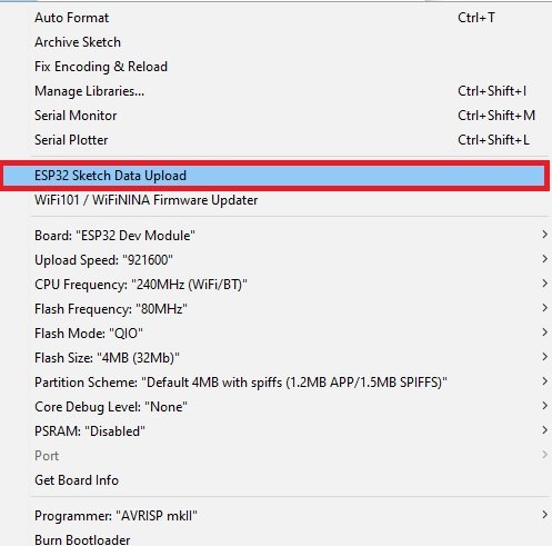
After a few moments, the file will be uploaded. You will receive the message ‘SPIFFS Image Uploaded’ on the debugging window.
Note: Make sure that the total size of the data file is within the flash memory size. Otherwise you will get an error while uploading the images onto SPIFFS.
Demonstration
Click on the upload button to upload the code to the ESP32 development board.
After you have uploaded your code to the development board, press its ENABLE button.

In your Arduino IDE, open up the serial monitor and you will be able to see the IP address of your ESP32 module.
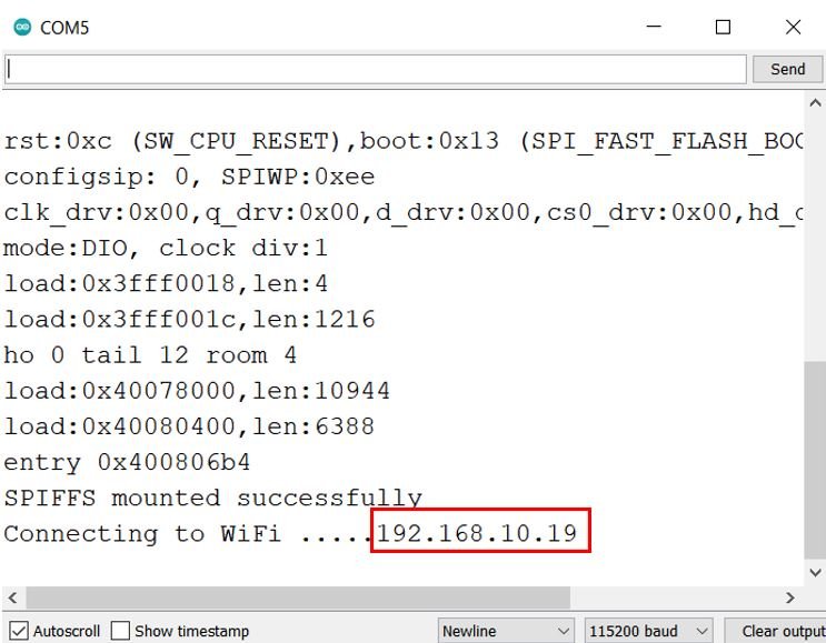
Type that IP address in a web browser and press enter. The web server will open up.
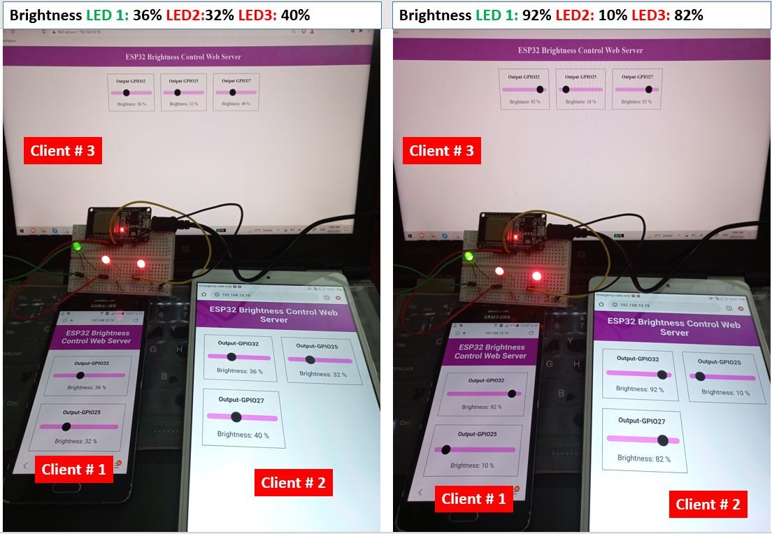
Now move the slider thumbs to the right and the slider values will start increasing. This will generate a PWM signals with the corresponding duty cycle values. Hence, the LEDs will start getting brighter. Once the value reaches 255, the LED will be brightest. Then start, moving the slider thumbs to the left thereby decreasing the slider values. This will cause the LEDs to fade until it turns OFF when the value reaches 0 again. The web server will immediately update in all the clients.
Have a look at the demonstration video below:
Other ESP32 tutorials, you may like to read:
Hello, if JavaScript functions are contained into the script.js file, why JavaScript functions still needed to be added into the code? Also missing from html file, aref to script.js file? Or is this linked by the script.js line at the end of the label ?
I did not understand your question.
hi, i need slider buttons but not cycle, just on off, also i want tosee change status. i dont know css html js.script, so i cant do it. please help me if you know same example? i can find just on-off slider buttons example but they didnt use websocket, they use webserver, but i need websocket and on-off slider buttons.
This is wonderful. Would I use similar code to link dht11 temperature data to a circular css style gauge or progress bar? I’m not a java programmer so I’m stumped. Do you have anything like that in your repitiore.