In this tutorial, we will create an internet based clock using MAX7219 LED Dot matrix display and ESP32. We will use the NTP server to acquire the current time and display it on the MAX7219 display. Firstly, we will learn how to get time from the NTP server using EPP32 and after that, we will see how to display the current time on MAX7219 dot matrix display in a 24-hour format consisting of HH: MM. You can further enhance this project to display both current time and date alternatively with some delay.
Recommended Components
The following components are used in this project or are helpful for building it with the ESP32.
| Component | How it’s used in this project | Buy on Amazon |
|---|---|---|
| ESP32 Development Board (DevKit V1) | The main controller that runs the project code and connects to the components. | Check Price |
| Micro USB Cable | Connects the ESP32 to your computer for programming and power. | Check Price |
| Breadboard | Lets you build the circuit and wire up parts without soldering. | Check Price |
| Jumper Wires | Make the connections between the ESP32 and the components on the breadboard. | Check Price |
| MAX7219 LED dot matrix | Displays the scrolling text and patterns driven by the ESP32 over SPI. | Check Price |
As an Amazon Associate we earn from qualifying purchases. Prices and availability are accurate as of the date/time indicated and are subject to change.
ESP32 Internet Based Clock – Getting Time from NTP Server
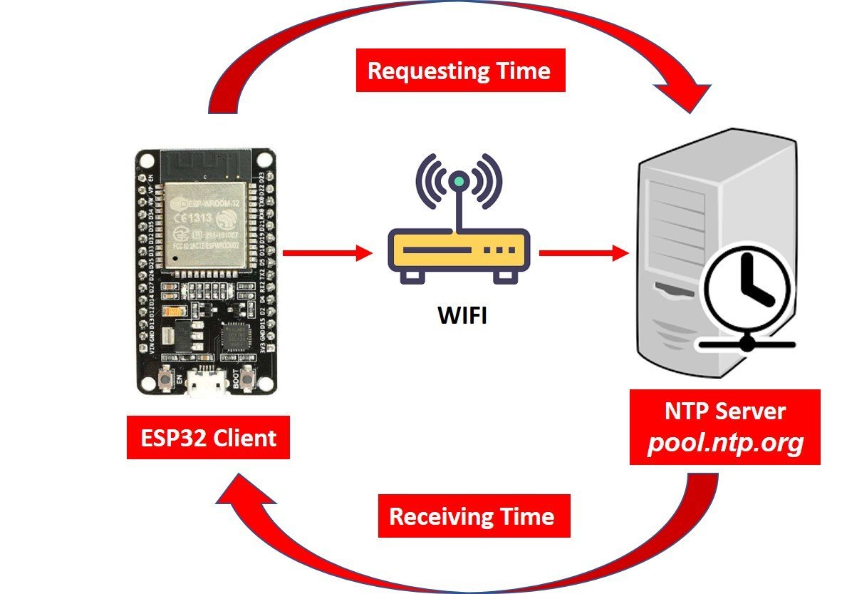
NTP is a standard internet protocol that is widely used to synchronize computer clocks to a reference network. With a precision of approximately 50ms over the wide-area network (WAN) and less than 5ms over the local area network (LAN), it synchronizes epoch/current time of all networked devices to the UTC.
To get the current time with ESP32 through the NTP server, the server will operate in the client-server model. We will use the NTP server: pool.ntp.org which is easily accessible for everyone worldwide. Our ESP32 development board will be the client and will connect to the NTP server through UDP on port 123. Through this port, the server (pool.ntp.org) will be able to connect with the client. After the connection is made, the ESP32 board will send a request to the server. When the NTP receives the request, it will transmit the time stamp containing the information regarding the time.
Related articles:
- Getting Epoch/Unix time with ESP32 through NTP server using Arduino IDE
- Epoch/Unix time with ESP8266 NodeMCU through NTP server using Arduino IDE
- Getting Current Date and Time with ESP32 using NTP Server-Client and Arduino IDE
- Current Date and Time with ESP8266 NodeMCU using NTP Server-Client and Arduino IDE
Getting Time from the NTP Server
We will upload a program code in our ESP32 board using Arduino IDE which will connect to the NTP server through our local network and we will request the current time. These values will then get displayed on our MAX7219 dot LED matrix and serial monitor automatically.
One thing to take into account while accessing the time for your time zone is to look for the Coordinated Universal Time (UTC) offset.
- For the UTC offset, click here to check for your time zone and add the offset in the program code by converting it in seconds.
For example, for the United States the UTC is -11:00 so converting it in seconds it becomes:
-39600 (-11*60*60).
For Pakistan, the UTC offset is +05:00 so in our code, we will specify the GMT offset which is the same as the UTC offset in seconds as 18000 (5*60*60).
MAX7219 LED Dot Matrix Display
Recommended Reading: MAX7219 LED Dot Matrix Display Interfacing with Arduino
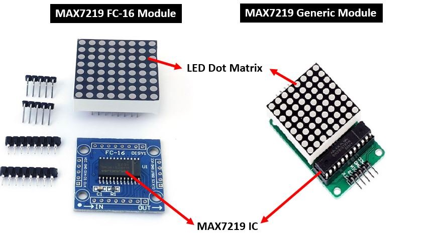
MAX7219 LED Dot matrix display is one of the popular ones available in the market and used by students, electronics hobbyists, and especially in industrial display applications. There are two types of modules generally available. These are the FC-16 module and the generic module.
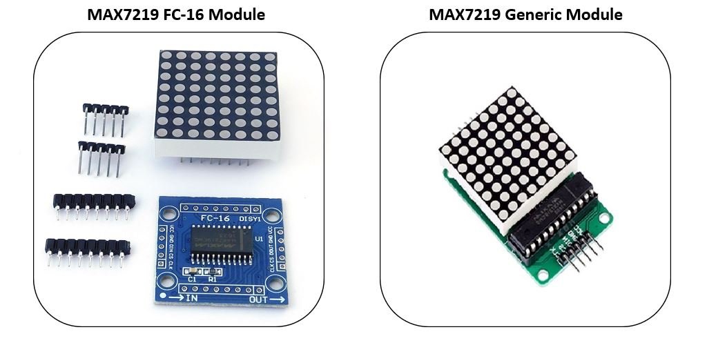
Each module consists of two units. One is the 8X8 LED dot matrix and the other is the MAX7219 IC.
You can find more information about MAX7219 here:
MAX7219 Dot Matrix Module Pinout
The MAX7219 module has 5 terminals consisting of SPI and power supply terminals. Both types of modules have the same connections on two sides. On one side are the input connections and on the other side are the output connections Below you can view the pinout of the generic module.
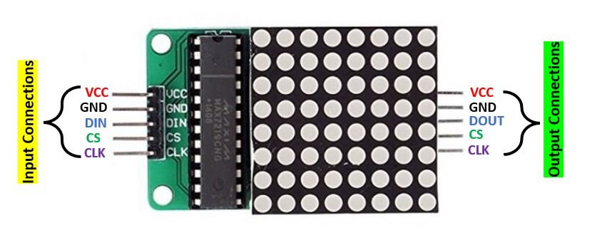
Input Connections
The input connections of the LED matrix are connected with the microcontroller, ESP32 in our case.
- VCC: This pin supplies power to the MAX7219 module. It is connected with Vin pin of ESP32 board.
- GND: This is the ground pin which should be connected with the ground pin of ESP32.
- DIN: This is the data in pin. It is used as the SPI input to the module.
- CS: This is the Chip Select pin for SPI communication.
- CLK: This is called the ‘Serial Clock’ pin which is used in SPI serial clock output.
Output Connections
The output connections of the LED matrix are connected with the next module if there is a need to attach more units.
- VCC: It is connected to VCC (5V) on the next module
- GND: It is connected to the GND on the next module
- DOUT: This is the Data out pin. It is connected to DIN pin of the next module.
- CS: This is connected to the CS pin of the next module
- CLK: This is connected to the CLK pin of the next module
MAX7219 LED Dot Matrix Module Interfacing with ESP32
Following components are required:
- ESP32 development board
- MAX7219 module
- Connecting Wires
For this project, we will be using the FC-16 module consisting of four units.

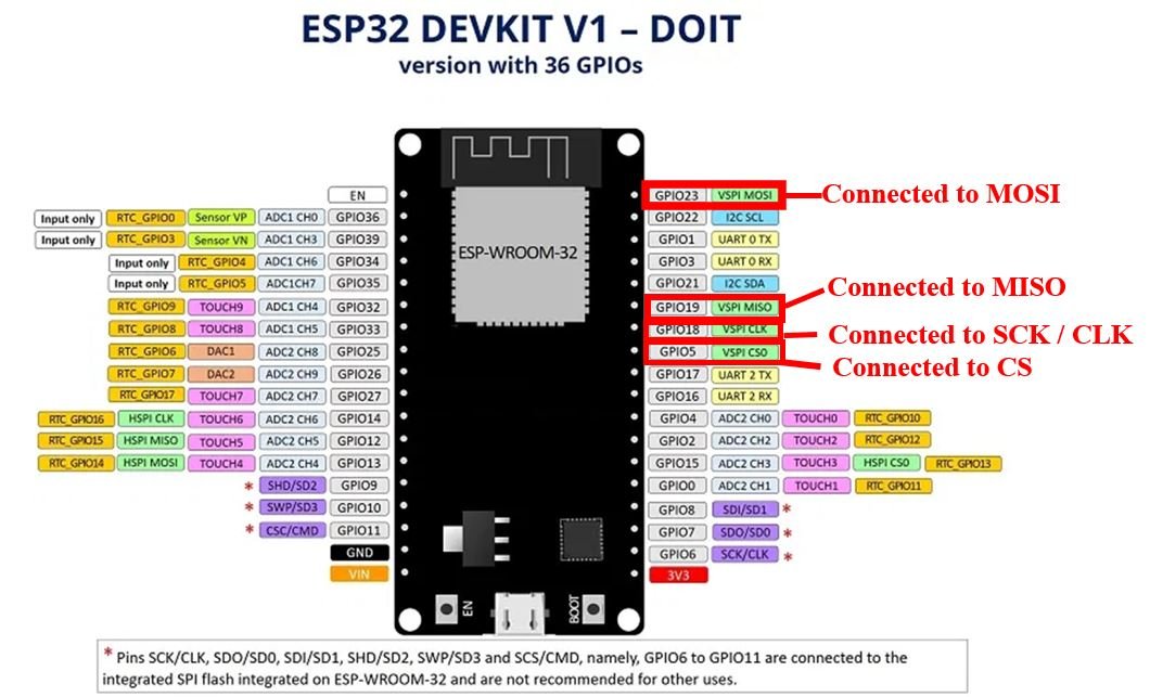
Now, we will show you how to connect the MAX7219 module and the ESP32 board together. The table below shows the default SPI pins for ESP32.
| Pin Names | ESP32 Pin |
|---|---|
| MOSI | GPIO23 |
| MISO | GPIO19 |
| SCK | GPIO18 |
| CS | GPIO5 |
The figure below shows the default SPI pins of ESP32.
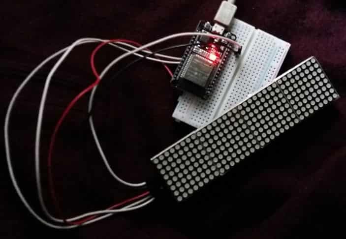
Now let us see how to connect the MAX7219 module and the ESP32 board. The table below shows the connections between the two devices:
| MAX7219 Module | ESP32 Pin |
|---|---|
| VCC | Vin |
| GND | GND |
| DIN | 23 |
| CS | 5 |
| CLK | 18 |
As shown from the table, we will connect the VCC terminal of the MAX7219 module with the Vin of the ESP32 board. This is because we will keep the brightness of the display at minimum inside the program sketch. Otherwise, use a separate 5V supply. Both grounds will be common. The default SPI GPIO pins of ESP32 are being used to connect with each of the remaining SPI terminals of the MAX7219 module.

Installing Arduino Libraries for Internet Based Clock
We will program our ESP32 board using Arduino IDE. Before we proceed further, you should make sure that you have the latest version of Arduino IDE installed on your system. Moreover, you should also install an ESP32 add-on in Arduino IDE. If your IDE does not have the plugin installed you can visit the link below:
Installing ESP32 library in Arduino IDE and upload code
Installing MAX7219 Arduino Libraries
To program our Arduino UNO board with the MAX7219 module we will be required to install two libraries: MD_MAX72XX by MajicDesigns and MD_Parola. These two libraries will make it very easy to program our development board.
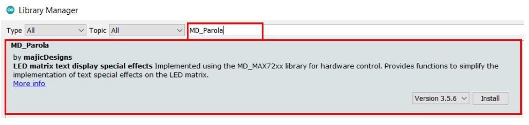
We will use the Arduino Library Manager to install these two libraries. Open your Arduino IDE and go to Sketch > Library > Manage Libraries. Type ‘MD_MAX72XX’ in the search bar and press enter. Install the library that is highlighted below.

Now type ‘MD_Parola’ in the search bar and press enter. Install the library that is highlighted below.
Installing NTPClient Library by Taranais
To request the current time from the NTP server we will use the NTPClient library by taranais available at Github. Follow the link:(https://github.com/taranais/NTPClient) to download it.
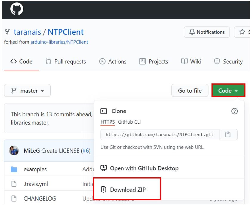
Click the Code button and go to the Download Zip option as highlighted in the figure. Your zip file will get downloaded to your computer right away. After the download is complete, extract the .zip file to the Arduino library folder. Make sure you rename the extracted file as ‘NTPClient.’ You can also go to Sketch > Include Library > Add .zip Library inside the IDE to add the library as well.
After installation of the libraries, restart your IDE.
Arduino Sketch: ESP32 Dot Matrix Clock using NTP server
Open your Arduino IDE and go to File > New to open a new file. Copy the code given below in that file.
This sketch will request the current time stamp through the NTP server and display it in a readable format on the Dot LED Matrix. You will have to replace the network credentials as well as set the UTC offset according to your location to obtain the correct current time.
#include <WiFi.h>
#include <NTPClient.h>
#include <WiFiUdp.h>
#include <MD_Parola.h>
#include <MD_MAX72xx.h>
#include <SPI.h>

#define HARDWARE_TYPE MD_MAX72XX::FC16_HW
//#define HARDWARE_TYPE MD_MAX72XX::GENERIC_H

#define MAX_DEVICES 4
#define CLK_PIN   18
#define DATA_PIN  23
#define CS_PIN    5
MD_Parola Display = MD_Parola(HARDWARE_TYPE, DATA_PIN, CLK_PIN, CS_PIN, MAX_DEVICES);

WiFiUDP ntpUDP;
NTPClient timeClient(ntpUDP);

const char* ssid     = "Your_SSID";
const char* password = "Your_Password";

String Time, hour, minute;
String Formatted_date;
long currentMillis = 0;
long previousMillis = 0;
int interval = 1000;

void setup() {
  Serial.begin(115200);
  WiFi.begin(ssid, password);
  while (WiFi.status() != WL_CONNECTED) {
    delay(500);
    Serial.print("Connecting.");
  }
  Serial.println("");
  Serial.println("WiFi connected.");

  timeClient.begin();
  timeClient.setTimeOffset(18000);

  Display.begin();
  Display.setIntensity(0);
  Display.displayClear();

}

void loop()
 {
   obtainTime();
}

void obtainTime() {
  while(!timeClient.update()) {
    timeClient.forceUpdate();
  }

  currentMillis = millis();

  if (currentMillis - previousMillis > interval)  {
previousMillis = millis();

Formatted_date = timeClient.getFormattedDate();
Serial.println(Formatted_date);

hour = Formatted_date.substring(11, 13);
minute = Formatted_date.substring(14, 16);


Time = hour + ":" + minute;
Serial.println(Time);
Display.setTextAlignment(PA_CENTER);
Display.print(Time);

}
}
How does the Code Work?
Now let us understand how each part of the code works.
Including Libraries
The first step is to include all the libraries that are necessary for this project. The SPI library will be used as we are using SPI communication protocol between the ESP32 board and the MAX7219 dot LED matrix. The WiFi.h will help the ESP32 board to connect to the local network whose credentials that we will provide in the program code. Additionally, we will also include the NTPClient library which we previously installed so that we will be able to request the timestamp from the NTP server. Moreover, we will include the MAX7219 module libraries that we previously installed for the proper functionality of the LED matrix.
#include <WiFi.h>
#include <NTPClient.h>
#include <WiFiUdp.h>
#include <MD_Parola.h>
#include <MD_MAX72xx.h>
#include <SPI.h>
Defining LED matrix type
Secondly, it is very important to define the correct type of MAX7219 LED matrix that you are using. We are using FC16. If you are using the generic model instead of FC16 then uncomment the second line and comment the line where we are defining FC_16HW.
#define HARDWARE_TYPE MD_MAX72XX::FC16_HW
//#define HARDWARE_TYPE MD_MAX72XX::GENERIC_H
Defining number of MAX7219 ICs
Thirdly, we will define the maximum number of ICs in our LED matrix. As we are using FC16 model thus it consists of four 8×8 LED arrays. Hence our maximum number of devices are 4.
#define MAX_DEVICES 4The next step is to specify the SPI pins used to connect the LED matrix and ESP32. We are using the default VSPI SPI pins in our case.
#define CLK_PIN   18
#define DATA_PIN  23
#define CS_PIN    5
We will then create an instance of MD_Parola library called ‘Display’ that will be set to the MD_Parola() function which takes in five arguments. The first argument is the hardware type. The second argument is the ESP32 pin connected with CS. The third argument is the ESP32 pin connected with the CLK. The next argument is the ESP32 pin connected with the CS. Lastly, the fifth argument is the number of MAX7219 ICs. We have defined all of these parameters earlier.
MD_Parola Display = MD_Parola(HARDWARE_TYPE, DATA_PIN, CLK_PIN, CS_PIN, MAX_DEVICES);Setting Network Credentials
Next, we will create two global variables, one for the SSID and the other for the password. These will hold our network credentials which will be used to connect to our wireless network. Replace both of them with your credentials to ensure a successful connection.
const char* ssid     = "Your_SSID";  //Write your SSID
const char* password = "Your_Password";   //Write your Password
Defining Variables
We will use the following lines of code to request the current timestamp from the NTP server.
WiFiUDP ntpUDP;
NTPClient timeClient(ntpUDP);
Next, we will define several variables. We will create string variables named ‘Time’, ‘hour’ , ‘minute’ and ‘Formatted_date.’ This will hold the current time.
String Time, hour, minute;
String Formatted_date;
Additionally, the following variables will keep track of the time by sending requests to NTP server after the set interval.
long currentMillis = 0;
long previousMillis = 0;
int interval = 1000;
setup()
Inside the setup() function, we will open a serial connection at a baud rate of 115200.
Serial.begin(115200);The following section of code will connect the ESP32 module with the local network. We will call WiFi.begin() and pass the SSID and password variables inside it which we defined before.
After a successful connection has been established, the serial monitor will display the message “WiFi connected.”
  WiFi.begin(ssid, password);
  while (WiFi.status() != WL_CONNECTED) {
    delay(500);
    Serial.print("Connecting.");
  }
  Serial.println("");
  Serial.println("WiFi connected.");
Next, we will initialize the NTP server by using begin() method on timeClient. We will also set the time offset so that we obtain the correct time according to our country. We have specified the offset for Pakistan but you can change it according to your time zone to obtain the correct time.
For the GMT offset, click here to check for your time zone and add the offset in the program code by converting it in seconds.
For Pakistan, the UTC offset is +05:00 so in our code, we have specified the GMT offset which is the same as the UTC offset in seconds as 18000 (5*60*60).
timeClient.begin();
timeClient.setTimeOffset(18000);  //Replace with your GMT offset (seconds)
Then, we will initialize the LED matrix by using the begin() function.
Display.begin();We will set the brightness to a minimum by passing 0 as a parameter inside setIntensity(). This function takes in values from 0-15 where 15 is the highest intensity. Moreover, we will clear the display by using displayClear().
 Display.setIntensity(0);
 Display.displayClear();
loop()
Inside the loop() function we will call the obtainTime() function.
void loop() {
obtainTime();
}
This function will request the current time from the NTP server after each interval and then display it on the LED matrix appropriately. This function takes in no parameter. It will request the current time from the NTP server and save this value in ‘Formatted_date’ This will be achieved by using timeClient.getFormattedDate(). In the serial monitor you will be able to view this timestamp. It will of the kind: 2021-08-23T22:15:35Z
We will have to split the date and the time. To do that we will use Formatted_date.substring() and acquire the hour and the minute value by passing the beginning Index as the first parameter and the ending Index as the second parameter. These values for ‘hour’ and ‘minute’ will get saved in the string variable ‘Time’ in the appropriate order.
Then we will display this string on the LED matrix. We will set the text aligned to the centre. This will be achieved by using setTextAlignment() and passing ‘PA_CENTER’ as a parameter inside it. Then by using Display.print() and passing ‘Time’ as the parameter inside it we will display the current time on the LED matrix. Additionally, the serial monitor will also display the current time.
void obtainTime() {
  while(!timeClient.update()) {
    timeClient.forceUpdate();
  }

  currentMillis = millis();

  if (currentMillis - previousMillis > interval)  {
previousMillis = millis();

Formatted_date = timeClient.getFormattedDate();
Serial.println(Formatted_date);

hour = Formatted_date.substring(11, 13);
minute = Formatted_date.substring(14, 16);

Time = hour + ":" + minute;
Serial.println(Time);
Display.setTextAlignment(PA_CENTER);
Display.print(Time);
}
}
Demonstration
Choose the correct board and COM port before uploading your code to the ESP32 board. Go to Tools > Board and select ESP32 Dev Module.

Next, go to Tools > Port and select the appropriate port through which your board is connected.

Now click on the upload button to upload code to ESP32. After that press the enable button on ESP32:

The LED matrix will start displaying the current time in 24-hour format showing the hour and minute.

Conclusion
In conclusion, we have learmed how to create an internet based clock using MAX7219 LED Dot matrix display and ESP32. The current time was requested from the NTP server in a very simple and easy way. By this procedure, we created our own digital 24-hour format clock.
HOW CAN I MADIFY THE CODE FOR ESP8266
Excellente explication, merci beaucoup.
why did you not give the ” include” part of the sketch?
let me check this might be an issue with backend.
HI my name is doron–in two month i will be 80
I builder your clock it work wonderfully thanks.
I have a problem that internet has many long pauses–so I try to modify so that with no internet the display will show the esp32 locat time and when internal will be on again the display will use it–all my effort came with ardurino errors.
I will be happy for help thanks doron
pordor@gmail.com
Compilation error: ‘class NTPClient’ has no member named ‘getFormattedDate’; did you mean ‘getFormattedTime’?
How can i solve this?
Thx, very useful and it works fine.
How to add a extra display for the i.e ‘seconds’ .
Is it possible to show the code for that?
thx, Arthur
That is very interesting for me too, so I hope you get an answer!
Hi,
I build this, and I’m very exited about it (nice explication!)
Only, I wonder, how many times is the server requested for the time?
Is that the interval of 1000 ms?
If I make that 3.600.000 ms for one hour, the time is not displayed anymore.
And if the server is questioned every second, is that not too often?
Thanks for the nice project,
Ruud.