MAX7219 is a common-cathode display driver IC with serial inputs and output pins. It has an adjustable current capability which can be set using only one external resistor. In addition to that, it has a four-wire serial interface that can be easily connected to all microprocessors. It can drive 64 individual LEDs connected at its output pins using only 4 wires by using Arduino. Furthermore, it can drive dot matrix displays, 7-Segments displays and bar graphs.
On top of that, MAX7219 has a built-in BCD decoder that makes it easy to use with seven segment numeric displays. Additionally, it has an 8×8 static RAM that we can use to store numbers. It is one of the most popular display driver IC.
MAX7219 Pinout Diagram
This picture shows a pinout diagram of the serially interfaced LED display driver IC.

Pin Configuration Description
This IC has a total of 24 pins. The description of pins is given below:
Pin#01: DIN
It is the serial data input pin. This IC has an internal 16-bit shift register. On every low to high transition of clock signal, the data is loaded into this register.
Pin#02, 03, 05, 06, 07, 08, 10, 11: Digit Pins
These are common output pins for all the segments of digits 0 to 7. These pins sink current from the display common cathode.
Pin#04, 09: GND
This is the ground of the circuit.
Pin#12: LOAD ()
It is the chip select pin. For normal operation, it is connected to low logic level to clock data in or out. On the positive transition of this input, the data is latched into the control register. After the 16th rising clock edge, this input must go HIGH otherwise all the data will be lost.
Pin#13: CLK
This is the serial input pin for the clock signal. When CS is low, the CLK input signal is active. On the positive edge transition of a CLK signal, data is shifted into the internal shift register. This data is displayed on the DOUT pin at the falling edge of the clock signal.
Pin# 14, 15, 16, 17, 20, 21, 23: SEG_A to SEG G
These seven pins are all segments of the digits.
Pin#22: SEG DP
This is the segment pin for a decimal point.
Pin#18: ISET
This pin is used to set the output current by connecting a resistor at this pin whose other terminal is connected to the ground. This resistor is used to adjust the value of the current.
Pin#19: V+
It is the terminal for a positive power supply.
Pin#24: DOUT
It is the serial digital output pins.
MAX7219 Features
- It is an LED driver display IC with a 10MHz serial interface which allows the user to select the decode/No-Decode digit.
- Its operation is specified in a voltage range of +4.0 to +5.5V. Normally, the voltage supply of +5V is used.
- It provides a feature of digital and analog brightness intensity control and a 150µA shutdown mode in which the current of all segments is pulled to ground.
- It consumes very low power.
- The data is displayed on segments with a delay time of 2.2ms.
- MAX7219 works well in a temperature range of 0°C to +70°C.
- The maximum current for each segment pin is 100mA and for each DIGIT ground pin is 500mA
Other Display Options
- Monochrome 0.96” OLED Display
- Nokia5110 LCD Module
- 2.4″ TFT LCD Display Module overview
- TFT Display
- TM1637- Grove 4 Digit Display Module
- 16×2 LCD Module – Liquid Crystal Display
- 7 Segment Display
Where to use it?
Due to its compact structure and four-wire serial interface, it can be connected to all common microprocessors (µPs), 7-segment LED displays, bar-graph displays, or 64 individual LEDs. One of the biggest advantages of using this IC is you can address Individual digits without rewriting the entire display. It saves processing time and speed.
How to use MAX7219?
A 16-bit data is sent at serial DIN input. On the rising edge of a clock input, this data is shifted into the 16-bit shift register integrated inside this chip. Then this data is passed to either the digit or control registers on the rising edge of LOAD/CS. Data is sent out at the serial output pin on the falling edge of CLK. The pins D0 to D7 contain data that is to be passed and D8 to D11 pins contain the address of the register.
Simple Example Circuit
A simple circuit is shown below which shows the MAX7219 connection with a microprocessor.
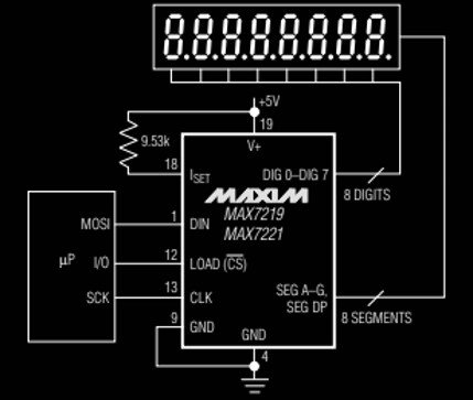
The display brightness can also be controlled. Connect an external resistor (RSET) between pins 18 and 19. The value of this resistor can either be fixed or variable for adjusting the brightness adjustment of the display panel. The intensity of light can also be controlled digitally through a pulse-width modulator present inside a chip. It has an in-built register known as scan-limit which sets the number of digits to be displayed, from 1 to 8.
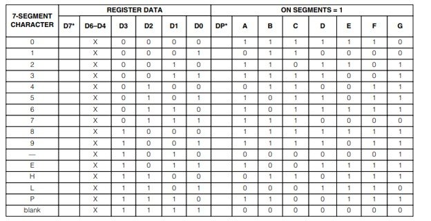
Decoder Mode Register
It has another register known as decode mode register which is used to sets BCD code B or no-decode operation for each digit. A high logic level is used to select code B decoding and low level for no-decode operation. In case of code B, the decoder looks only at only D3-D0. D7 pin is used to set the decimal point. When this pin is High, it turns the decimal point on. The truth table for code B is given below.
MAX7219 Applications
This IC is used in:
- LED Matrix for controlling LED lights
- Industrial Controllers
- Bar-Graph Displays
- Panel Meters
MAX7219 Tutorials and Projects
- MAX7219 Interfacing with Pic Microcontroller
- 74HC595 Serial Shift Register Interfacing with Pic Microcontroller
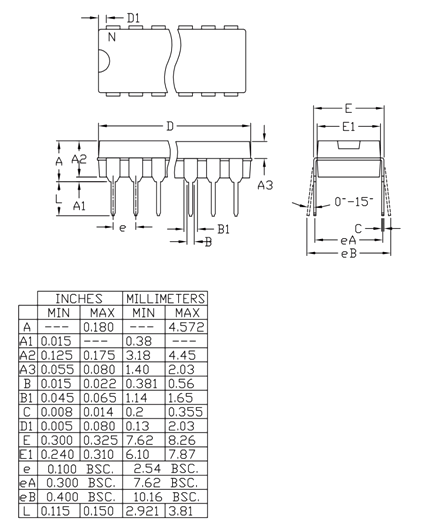
2D Diagram
Other Electronics Components:
- HC-SR505 PIR motion sensor Module
- 74LS48 BCD to 7-Segment decoder
- LM350 Adjustable Output, Positive Voltage Regulator
- RFID reader RDM630 interfacing with pic microcontroller
- PIC Microcontroller ADC –
- 24C04 Two-Wire Serial EEPROM I
- HMC5883L 3-Axis Compass Module
- CD4014 8-Stage Static Shift Register IC
- CCS811 Indoor Air Quality Gas Sensor
- CD4017 Counter IC Examples
Your blog is one thing I check almost everyday on the internet. With great and reliable information people can learn, know and grasp many aspects happening around the world. Well, I am happy to read your blog section. Thank you for posting fruitful content.