In this tutorial, we are going to introduce you to the ESP32 development board. You might have used other Microcontrollers such as Arduino, PIC, TM4C123, STM32, and ESP8266 in the past. But when it comes to ESP32 then it has many advantages over the aforementioned microcontroller in terms of processing power, on-chip RAM, and Flash. In this article, we will have a look at ESP32 specifications, key features, pins layout of ESP32 dev kit, and one getting started example.
If you are just getting started with ESP32, we recommend you to download Arduino IDE and install ESP32 library package in it by following this tutorial:
if you want to purchase ESP32 development board, you can purchase it from this link: ESP32

There are many ESP32 chip variants available in the market and also there are many development kits available based on those chips. In this tutorial, we will use the ESP-WROOM-32 Dev kit as a reference.
ESP32 Development Board Introduction
The ESP32 is a microcontroller that belongs to the category of low-power and cost-effective on-chip microcontrollers. Almost all ESP32 variants have integrated dual-mode Bluetooth and Wi-Fi, making it highly versatile, robust, and reliable for a wide range of applications.
It is a successor to the popular ESP8266 NodeMCU microcontroller and provides better performance and features. The ESP32 microcontroller is manufactured by Espressif Systems and is widely used in a variety of applications such as IoT, robotics, and automation.
The ESP32 also includes a variety of peripherals such as GPIO, I2C, SPI, UART, ADC, CAN, etc which makes it easy to interface with other devices. You can learn more about the use of these peripherals in the following tutorials:
- GPIO pins of ESP32 – LED Blinking example
- Push button with ESP32 – GPIO pins as digital input
- ESP32 touch sensor – How to use touch pins as a button
- ESP32 SPI Tutorial Master Slave Communication Example
- ESP32 I2C Communication Set Pins, Multiple Devices Interfaces, and Change Pins
The ESP32 is also designed for low power consumption, making it ideal for battery-powered applications. It features a power management system that allows it to operate in sleep mode and wake up only when necessary, which can greatly extend battery life.
You can learn to use sleep modes of ESP32 in the following tutorial:
To know more about each GPIO pins of this development board, check this tutorial:
Different ESP32 Variants
The following table provides a comparison of various variants of the ESP32 microcontroller. It includes information on the architecture, cores, RAM, speed, GPIO, Wi-Fi, Thread, and special features of each variant.
| Variant | Available | Architecture | Cores | RAM | Speed (max) | GPIO | Wi-Fi (802.11) | Thread (802.15) | Feature |
|---|---|---|---|---|---|---|---|---|---|
| ESP32 | Yes | Xtensa | 2 | ±320 KiB | 240 MHz | 34 | 2.4 G | No | |
| ESP32-S2 | Yes | Xtensa | 1 | 320 KiB | 240 MHz | 43 | 2.4 G | No | USB OTG |
| ESP32-S3 | Yes | Xtensa | 2 | 512 KiB | 240 MHz | 44 | 2.4 G | No | AI instruction set / USB OTG |
| ESP32-C3 | Yes | RISC-V | 1 | 400 KiB | 160 MHz | 22 | 2.4 G | No | |
| ESP32-C5 | No | RISC-V | 1 | 400 KiB | 240 MHz | 20 | 2.4 G / 5G | No | 5G |
| ESP32-C6 | Yes | RISC-V | 2 | 512 KiB | 160 MHz / 20 MHz | 30/22 | 2.4 G (Wi-Fi 6) | Yes | Thread and Wi-Fi |
| ESP32-H2 | No | RISC-V | 1 | 256 KiB | 96 MHz | 26 | No | Yes | |
| ESP32-P4 | No | RISC-V | 3 | 768 KiB | 2 x 400 MHz / 40 MHz | 50+ | No | No | Hardware encoding for media |
Note: “Yes” means that the variant has the feature, and “No” means that the variant does not have the feature.
The first column indicates whether a particular variant is available in the market or not. The second column specifies the architecture used in the microcontroller, which is Xtensa for the ESP32, ESP32-S2, and ESP32-S3, and RISC-V for ESP32-C3, ESP32-C5, ESP32-C6, ESP32-H2, and ESP32-P4. The number of cores available in each variant is also mentioned, ranging from one to three. The third column specifies the amount of RAM available in each variant, which ranges from 256 KiB to 768 KiB.
The maximum speed that each variant can achieve is specified in the fourth column. It ranges from 96 MHz to 400 MHz, depending on the variant. The number of GPIOs available in each variant is listed in the fifth column, ranging from 20 to 50+. The sixth column indicates whether the variant supports Wi-Fi, and the maximum Wi-Fi standard (2.4 G, 5G, or Wi-Fi 6) is supported. The seventh column indicates whether the variant supports Thread, which is a low-power wireless protocol used for IoT devices. Finally, the last column lists the special features of each variant, such as USB OTG, AI instruction set, hardware encoding for media, etc.
Overall, the table provides a comprehensive comparison of the various ESP32 variants, allowing developers to choose the one that best fits their needs based on the number of cores, RAM, speed, GPIO, Wi-Fi, Thread, and special features required for their particular application.
ESP32 Vs Other Microcontrollers
When comparing ESP32 microcontrollers with other microcontrollers, one of its significant advantages is having integrated Wi-Fi and Bluetooth modules. While some microcontrollers can add Wi-Fi through shields or adapters, it is not a native feature of the board, which increases the cost of the board. In contrast, ESP32 comes with already integrated Wi-Fi and Bluetooth modules, making it a more cost-effective option for those interested in using these features.
Moreover, adapters for Wi-Fi and Bluetooth are generally expensive, which can be a challenge for hobbyists or small-scale projects. In comparison, ESP32’s built-in Wi-Fi and Bluetooth modules offer greater versatility, robustness, and reliability in a wide range of applications, such as IoT, MQTT-based Gateways, MP3 decoding, voice encoding, and video streaming. Additionally, ESP32 comes with a USB port, making it a plug-and-play device that can be programmed like other microcontrollers, with details on programming to be discussed later.
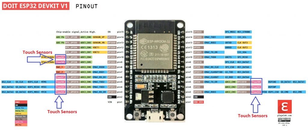
ES32 WROOM-32 Devkit Pinout
The ESP32 microcontroller offers a pin multiplexing feature that enables us to select which peripherals to connect from 28 input/output pins. This feature provides us with the flexibility to decide which pins we want to use for which peripheral such as MISO, RX, SCLK, MOSI, TX, SCL, SDA, and several other options. However, some pins for the analog-to-digital converter and digital-to-analog converter are dedicated to these peripherals and cannot be configured as per the user’s requirements.
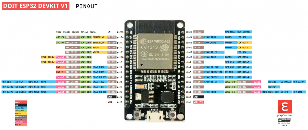
- Analog to digital converter (ADC) channels are 18
- SPI interfaces are 3
- UART interfaces are 3
- I2C interfaces are 2
- PWM outputs are 16
- Digital to analog convertors (DAC) are 2
- I2S interfaces are 2
ESP32 on-chip Sensors
- Hall sensors
- 32 kHz crystal oscillator
- Ultra-low noise analog amplifier
- 10x capacitive touch interfaces
Programming ESP32
To power on the ESP32 development board, we have the option to use either the USB port or LiPo battery. When both power sources are connected, some development boards have a charge controller integrated which charges the LiPo battery. Moreover, the board has a 3.3 V voltage regulator that can deliver a current of 600 mA. During RF transmission, the board can consume up to 250 mA. It is important to note that the general-purpose input-output pins cannot handle 5 V, and hence, level shifting is required to interface the board with 5 V.
For programming the ESP32 board, we can use the Arduino IDE. However, certain drivers and libraries must be installed to make it compatible with the IDE and ready to use. Below is a brief explanation of the necessary drivers and libraries.
Install Drivers
The very first and most important thing to program this board is to install CP210x USB – UART drivers. Depending on your operating system, install the proper drivers.
Install ESP32 Library in Arduino IDE
You can install libraries for ESP32 by using GitHub. After installing all these drivers and libraries you are ready to program your board. You can use Terminal in MAC or command line in windows operating system to install these libraries from GitHub.
Once you are done with installation of required drivers and libraries you have to restart Arduino IDE and you are ready to go. After restarting your Arduino IDE you will see several boards added in the tools menu of Arduino IDE. Now select your appropriate board.
Getting Started Example
So the first program we are going to discuss is blinking of a LED. All code for LED blinking will be written in Arduino IDE. There is a built in led in ESP32 development kit that is connected to general purpose input / output pin 02. One more thing we need to check before writing our code is to ensure that our built in led in ESP32 development board is supported by Arduino IDE. If it is recognized by Arduino IDE then you are ready to write your code otherwise you have to make it recognizable by Arduino IDE by using following piece of code
- int LED_BUILTIN = 2;
Each ESP32 board is having an internal led connected but they are connected to different general purpose input output pins. In our case, an internal blue led is connected at general purpose input output pin. So let’s write our piece of code.
/*
  ESP 32 Blink
  Turns on an LED on for one second, then off for one second, repeatedly.
  The ESP32 has an internal blue LED at D2 (GPIO 02)
*/

int LED_BUILTIN = 2;

void setup()
{
  pinMode(LED_BUILTIN, OUTPUT);
}

void loop()
{
  digitalWrite(LED_BUILTIN, HIGH);   // turn the LED on (HIGH is the voltage level)
  delay(1000);                       // wait for a second
  digitalWrite(LED_BUILTIN, LOW);    // turn the LED off by making the voltage LOW
  delay(1000);                       // wait for a second
}
Program flow of every code that we write in Arduino IDE is that first we initialize variables. Variables can be local or global. We will not go in the details of these local and global variables. After variables initialization, our setup function will be called that is used to assign values of initialized variables and then our loop function is called. Setup function will be called only once while loop function as obvious from name will run continuously in organized manner. If we want to call setup function again then we have to re-run our program or restart our development board either by using rest button on board or by disconnecting and connecting our board again.
So if we have a look at our code by keeping the points stated above in our mind, we first have initialized our built-in LED at general purpose input output pin 2. After initialization of this built-in LED we can see that the initialization and purpose of this led that whether it is acting as input or output. After assigning it as output we go the loop function which will run endlessly unless and until we disconnect our board or stop running this program. In our loop function we first turned on our led using DigitalWrite function and assigning our led high voltage, then we waited for 1 second delay and then turned off our led by assigning low voltage to our led and then waited for another sec and so the loop continues i.e. this loop will turn on the led for 1 sec and then turn if off for 1 sec and it continues. you can now check these:
Price of ESP32 Dev Board??
you can find it around 10-15$
Hi freaks
Compiling “ESP 32 Blink” (above) with Arduino IDE generates an error.
Resolve the problem by replacing line:
int LED_BUILTIN = 2;
by
#define LED_BUILTIN 2
Now it works great!
Thats Great
I think My board does not have built-in LED. How to know if it is present or not?
Also I searched in datasheet and pinout but I am unable to find out the exact details of my board.
could you please help me?