Push button with ESP32 – GPIO pins as digital input, In this ESP32 tutorial, we will teach you how to use GPIO pins of ESP32 as digital input pins and how to interface a push button with the ESP32 development board. The push button is used to provide a user interface to users to send external events signals to microcontrollers.
For example, we can control devices such as LEDs, motors, relays, etc, by using these push buttons as an external event source. Similarly, we can use push buttons to increase or decrease the speed of the dc motor. To use the push button with ESP32, we will configure GPIO pins as a digital input pin to read the state of a push button. The push button will give two logical states either high or low depending on in which configuration push it is connected such as pull-up or pull-down. We will learn about pull-up and pull-down circuits in the later part of this tutorial.
In the last tutorial, we learned how to use the GPIO pins of ESP32 as digital output pins by creating an LED blinking example. If you don’t know how to configure GPIO pins as digital outputs pins, you can refer to the following article:
GPIO pins of ESP32 – LED Blinking example
We have a similar guide with MicroPython:
ESP32 and ESP8266 GPIO Programming with MicroPython – LED Blinking Example
Recommended Components
The following components are used in this project or are helpful for building it with the ESP32.
| Component | How it’s used in this project | Buy on Amazon |
|---|---|---|
| ESP32 Development Board (DevKit V1) | The main microcontroller board that runs the project code and controls all connected parts. | Check Price |
| Micro USB Cable | Connects the ESP32 to your computer to upload code and provide power. | Check Price |
| Breadboard | Lets you build the circuit and connect components without soldering. | Check Price |
| Jumper Wires | Used to wire the ESP32 to the other components on the breadboard. | Check Price |
| Tactile push button | The digital input button read by the ESP32 GPIO pin in this example. | Check Price |
| Resistor Kit (220 Ω / 4.7k) | Provides a 10k pull-down/pull-up resistor for the push button input. | Check Price |
As an Amazon Associate we earn from qualifying purchases. Prices and availability are accurate as of the date/time indicated and are subject to change.
Push Button Interfacing Configurations
There are two configuration modes to interface a push button with the ESP32 board. Let’s discuss both these modes one by one.
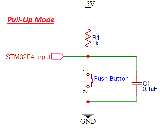
Pull-Up Mode
In Pull-up mode, when a push button is not pressed, a logic high input appears on the ESP32 GPIO pin. Because a 5V signal appears on the input terminal through an R1 resistor. On the contrary, when the push button is pressed, metallic contacts of the push button make contact with the ground terminal and the input terminal. Therefore, a logic low input reflects on the digital input pin of the ESP32 board. In short, by reading this state of the push button with a digital input pin of a microcontroller, we can identify whether a push button is pressed or not. The following schematic diagram shows the connection of a push button with a pull-up resistor.
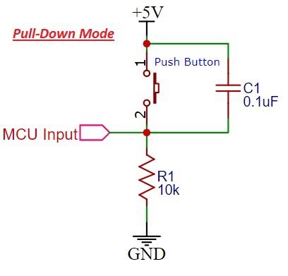
Pull-Down Mode
In Pull-down mode, when a push button is not pressed, a logic low input appears on the ESP32 GPIO pin. Because a ground reference signal appears on the input terminal through an R1 resistor. On the contrary, when the push button is pressed, metallic contacts of the push button make contact with the +5V signal and the input terminal. Therefore, a logic high input reflects on the digital input pin of ESP32 board. The following schematic diagram shows the connection of a push button with a pull-up resistor.
Push button interfacing with ESP32
The push button can be interfaced with ESP32 either through a pull-up resistor or a pull-down resistor. In Pull up resistor mode, when the push button is not pressed, input to the GPIO pin will be logic high or vice versa.
In pull-down resistor mode, when the push button is pressed, input to the GPIO pin will be logic low state and otherwise logic high state.
So We will use the digital input pin of the ESP32 development board to read this logic using pinMode() function of Arduino IDE. So now let’s start with a circuit diagram of push-button interfacing with esp32 and after that, we will see how to write code for this.
If you are a beginner and do not have an idea about the ESP32 development board, you can check this guide:
Arduino IDE is used to program ESP32 in these series of tutorials and we can install an ESP32 board in Arduino IDE. You can check this tutorial:
So now let’s perform a simple example to connect a push button with any GPIO pin and turn on an LED connected to another digital pin.
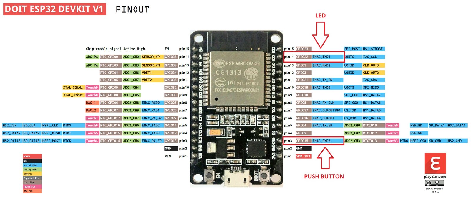
As shown in the above pinout, we will be using GPIO15 to connect the push button and GPIO22 to connect a push button. We can use any GPIO pin either as digital input or digital output pins except a few GPIO pins which can be used only as digital input pins for more information about it check ESP32 pin out the tutorial.
ESP32 Digital input GPIO pins
All GPIO pins of ESP32 can be used as digital input pins. But ESP32 has four GPIO pins which can be used as digital input pins only. They cannot be configured as digital output pins. Also, unlike other GPIO pins, these pins do not have internally connected push-pull resistors. Therefore, when using any one of these pins as a digital input pin, we need to connect an external pull-up or pull-down resistor.
- GPIO34
- GPIO35
- GPIO36 (VP)
- GPIO39 (VN)
Circuit diagram of Push button with ESP32
The Schematic diagram for push button interfacing is shown below:
In this circuit diagram, the push button is connected to ESP32 in pull-down configuration mode.
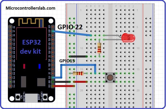
In the above circuit diagram, GPIO22 is connected with an anode pin of LED, and another pin of LED is connected with ground through a 330ohm resistor. you can check the LED blinking tutorial for more information about it.
Next push button one terminal is connected with 3.3 volts of ESP32 and the other terminal of a push button is common with GPIO15 and resistor.
Another end of the resistor is connected to the ground. When the push button is not pressed, logic low will appear on GPIO15, or the push button state will be low and when the push button is pressed, a logic high will be on GPIO15.
ESP32 will read these two states of the push button and turn on and turn off LED accordingly.
ESP32 Push Button Code
The code for the push-button interface with ESP32 is given below.
// We assigned a name LED pin to pin number 22
const int LEDPIN = 22;
// this will assign the name PushButton to pin numer 15
const int PushButton
// This Setup function is used to initialize everything
void setup()
{
// This statement will declare pin 22 as digital output
pinMode(LEDPIN, OUTPUT);
// This statement will declare pin 15 as digital input
pinMode(PushButton, INPUT);
}

void loop()

{
// digitalRead function stores the Push button state
// in variable push_button_state
int Push_button_state = digitalRead(PushButton);
// if condition checks if push button is pressed
// if pressed LED will turn on otherwise remain off
if ( Push_button_state == HIGH )
{
digitalWrite(LEDPIN, HIGH);
}
else
{
digitalWrite(LEDPIN, LOW);
}
}
All the functions used in this code are the same as used in the last tutorial on LED blinking except one function digitalRead function. Now let’s see how to use the digitalRead() function.
ESP32 GPIO State Readi Function (digitalRead(Pin_number))
This digital read function is used to read the state of the input pin. This digitalRead function returns either logical HIGH or logical LOW input. If the input state of the pin is HIGH, it will return HIGH and otherwise low. You only need to pass the pin number as an augment to this function.
For example in this tutorial, we are using pin number 15 as a digital input, so we will use this function like this digitalRead(22) or we can define 22 with any name and use name instead of pin number as we did in the example code below:
This is the simple code used to read the state of the push button or any switch. Now let’s see how the code works.
In the code, the first 2 lines give a name to input pin 15 as PushButton and output pin 22 as LEDPIN. So now inside the code, we can use these names instead of pin numbers.
// We assigned a name LED pin to pin number 22
const int LEDPIN = 22;
// this will assign the name PushButton to pin numer 15
const int PushButton
In the setup() function, we use the pinMode() function to initialize the PushButton pin as an INPUT and LEDPIN as an INPUT.
// This statement will declare pin 22 as digital output
pinMode(LEDPIN, OUTPUT);
// This statement will declare pin 15 as digital input
pinMode(PushButton, INPUT);
In the loop() function, the digitalRead function reads the state of the push button and stores its value in the variable Push_button_state.
/ digitalRead function stores the Push button state
// in variable push_button_state
int Push_button_state = digitalRead(PushButton);
After that, if condition block checks the state of the variable Push_button_state. If the state of the push button is active high and the ‘if’ condition is true, set the LED to active high, and otherwise, set it to active low.
// if condition checks if push button is pressed
// if pressed LED will turn on otherwise remain off
if ( Push_button_state == HIGH )
{
digitalWrite(LEDPIN, HIGH);
}
else
{
digitalWrite(LEDPIN, LOW);
}
If Push_button_state gives output HIGH, LEDPIN will be turned on and otherwise, it will remain off.
In the above code, we have used the polling method to read the state of the input pin, the issue with the above is that the ESP32 keeps checking the state of the push button by polling the input pin. But one of the main drawbacks of the polling method is that the microcontroller will have to check the status of input switches on every sequential execution of the code or keep monitoring continuously (Polling method). Therefore, external or GPIO interrupts can be used to synchronize external physical devices with microcontrollers. If you want to use ESP32 external interrupts, you can read the following article:
After going through this guide, you will surely be able to use the GPIO pins of ESP32 as digital input pins. You can also check other ESP32 tutorials:
- Analog to digital converter channels of ESP32 and measuring voltage tutorial
- ESP32 touch pins – How to use touch pins as a digital button
- Step by step guide on built-in hall effect sensors of ESP32
- Pulse width modulation channels of ESP32 with a fix and variable duty cycle PWM generation
- I2C LCD interfacing with ESP32
- Assigning Fix/Static IP address to ESP32
- ESP32 based web server in Arduino IDE – How to control LEDs from server
- ESP32 soft access point web server in Arduino IDE
- ESP32 web server in Arduino IDE – Servo motor control
- ESP32 web server to display sensors data in Arduino IDE
- Password protected web server with ESP32 and Arduino IDE
- Access ESP32 web server from anywhere in the world
Hi for the gpio15 they show it as having already a pullup resistor inside.. So is the extra resistor you put can be omit ? thanks
yes if you configure internal resistor, you can omit the external resistor
Hi!
But then the wiring has to be different – if you use internal pullup…
in the Code:
this line: const int PushButton
should be: const int PushButton = 15
or you use
#define PB_PIN = 15
#define LED_PIN = 22
because there is no need to change the pin inside the Code
nice detailed guide here. by far the clearest in the google results but where is the micropython code?
I don’t get it. There is no info for ESP that PushButton is on pin15…So is it an error or it’s like default that its on pin15?
“// this will assign the name PushButton to pin numer 15
const int PushButton “.
2nd thing. I have connected PINs 12 and 13 to ground through push button and wrote DigitalRead to control motor. Now its super sensitive, triggering even disconnected, but touched by hand. Did i damaged it by not using resistor?
if(digitalRead(13)) {
analogWrite(25, 0);
analogWrite(26, 255);
}
else {
if(digitalRead(12)) {
analogWrite(26, 0);
analogWrite(25, 255);
bien oui il faut ajouter =15 à la ligne const int PushButton =15 sinon il serait médium cet esp32 🙂
// We assigned a name LED pin to pin number 22
const int LEDPIN = 22;
// this will assign the name PushButton to pin numer 15
const int PushButton =15
// This Setup function is used to initialize everything
In place of a push button, I want to use a physical wall switch.
How do I pull up/pull down externally.
I don’t want to pull anything from the inside.
Also, I don’t want my module to be powered all the time.
Instead, I want to put it on a standby mode.
So that when I virtually click on a button through a phone application, I can turn it on automatically.
How can I do it ?
Push buttons should be debounced and that code is missing. It could cause false flickers.
Yes, you are right. You may like to check these tutorials where we added debouncing effect code also:
http://microcontrollerslab.com/esp32-esp8266-control-outputs-with-web-server-and-push-button-simultaneously/
http://microcontrollerslab.com/esp32-esp8266-momentary-switch-web-server-control-gpio-outputs/
We have not introduced debouncing effect in this tutorial to not confuse newbies.
Is there a way to detect a button is pressed when power is applied? I have an ESP32-CAM with an application that uses a trigger button to snap a pic and want to have a “factory reset” option for the camera’s settings. So I’m thinking if it detects the button is pressed & held when first starts up, that would trigger the reset.
I keep receiving false flickering on my ESP8266 GPIO pins that are supposed to be standing by waiting for my signal and my signal only to produce an output upon command.How do I prevent this from occurring?
I know this is being a bit picky, but I your text describing the PULL-DOWN operation, the last sentence says “The following schematic diagram shows the connection of a push button with a pull-up resistor.” This of course should say “The following schematic diagram shows the connection of a push button with a pull-down resistor.
I have a question regarding your answer to Jeff where you said “yes if you configure internal resistor, you can omit the external resistor” . How do you configure the internal resistor? I would have thought it was permanently there as part of the ESP32 internal circuitry. I have been using GPIO pin13 as a digital input and did not use an external pull up resistor; this caused random results when I did a digital read on the pin unless the switch connected to the pin was closed (connecting the pin directly to ground). Only after I added a 10k ohm external resistor was I able to get consistent results of HIGH and LOW when the switch was open and closed respectively.
pinMode(BUTTON_PIN, INPUT_PULLUP);
hello, from the diagram, it seems that 5v is attached to the MCU input. Is it safe? Should it be 3.3V?