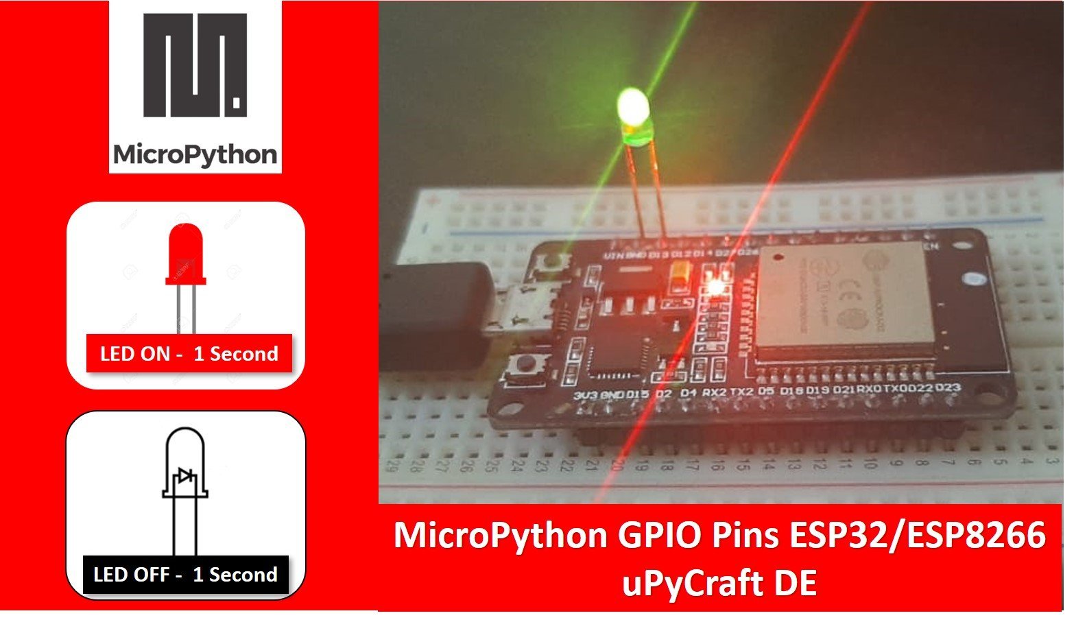
In this tutorial, we will learn about how to use GPIO pins of ESP32 and ESP266 using the MicroPython programming language. For demonstration purposes, we will, first, take an LED blinking example. After that, we will see an LED chaser example in MicroPython using uPyCraft IDE. We will discuss GPIO pin examples for both ESP32 and ESP8266 development boards.
Recommended Components
The following components are used in this project or are helpful for getting started with MicroPython on ESP32 and ESP8266.
| Component | How it’s used in this project | Buy on Amazon |
|---|---|---|
| ESP32 Development Board (DevKit V1) | The ESP32 board flashed with MicroPython firmware. | Check Price |
| ESP8266 NodeMCU (ESP-12E) | The ESP8266 NodeMCU running the same MicroPython code. | Check Price |
| Micro USB Cable | Programs and powers the board from your PC. | Check Price |
| 5mm LED | The external LED that blinks on GPIO13. | Check Price |
| Resistor Kit (220Ω) | Current-limiting resistor in series with the LED. | Check Price |
| Breadboard | Holds the LEDs and resistors for prototyping. | Check Price |
| Jumper Wires | Connect the LEDs and resistors to the board. | Check Price |
As an Amazon Associate we earn from qualifying purchases. Prices and availability are accurate as of the date/time indicated and are subject to change.
We have similar article to control ESP32 LED with Arduino IDE:
Prerequisites for LED Blinking Tutorial
In order to start, make sure you have performed the following procedures already:
- Downloaded and installed the latest version of Python 3 on your PC.
- Downloaded and installed the latest version of the uPyCraft IDE.
- Flashed your MicroPython firmware with your module Esp32/Esp8266.
If you want to know how to perform above steps, you can follow this step by step guide:
If you are using Thonny IDE, you can check this getting started guide:
After the above mentioned procedures have been followed now, we will learn how to blink a single LED with our ESP boards using MicroPython and uPyCraft IDE. Let us learn about the GPIOs for both Esp32 and Esp8266 to help us better understand the connections.
What are GPIOs?
GPIO is the abbreviated form of General Purpose Input/Output. These are digital signal pins found on the module which can be used as the input, output, and even both of them can be used together. These are controlled by us during run time.
ESP32 and ESP8266 GPIO Pins
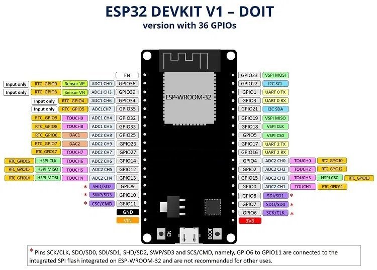
There are various versions Esp32 with different number of GPIOs. The one which we will look at has 36 GPIO pins. As compared to Esp8266 it has more GPIO pins hence better functionality. We can use the pins as they are set in default or can even change them using coding. The diagram below shows the GPIO pins for Esp32 as they are set in default.
ESP32 GPIO Pins
ESP32 chip used with this board has 48 GPIO pins, but all pins are not accessible through development boards. That means not all GPIO pins are exposed to the pinout. ESP32 devkit has GPIO 39 pins. But GPIO6 to GPIO 11 are not exposed on pinout in all ESP32 development boards. Because these pins are internally connected to the integrated SPI flash on the ESP-WROOM-32 chip. Therefore, it is not recommended to use these pins as digital input or digital output pins in your project. Each pin has multiple functionalities which can be configured using specific register. You should read the following article to know more about GPIO pins of ESP32.
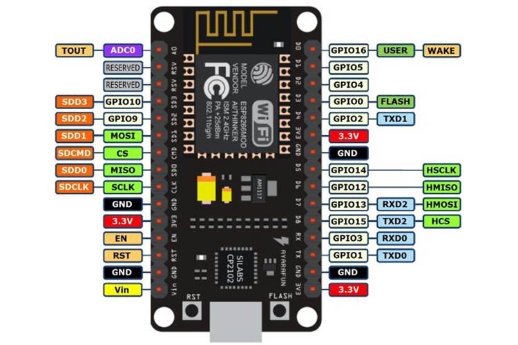
ESP8266 GPIO Pins
As mentioned earlier, there are many types of ESP32 development boards available in the market. Similarly, there are many options available for ESP8266 development boards. But we will use the most used ESP8266 12-E NodeMCU Kit in this tutorial.
ESP8266 has 17 GPIOs starting from GPIO0 to GPIO16. But not all pins are exposed to the pinout of the ESP8266 12-E NodeMCU Kit. GPIO6 to GPIO11 are connected to the SPI flash internally. The pins which are exposed to the pinout of ESP8266 12-E NodeMCU Kit are showing below:
For in-depth details on pinout and GPIO pins of ESP8266 NodeMCU Kit, check the following tutorial:
Blinking LED using ESP 8266/ESP32
Now we will start our project to blink an LED using ESP 8266/ESP 32 in MicroPython with the help of uPyCraft IDE. Open the IDE and go to Tools>Board and select the board which we will use. In our case ESP 8266 or ESP 32. Next, go to Tools>Port and select the Com port on which our module is connected. Now click on the Connect/Disconnect button to make sure the module is connected serially with the program. In order to perform this project, we need the following equipment:
- Breadboard
- One LED
- One 220 ohm resistor
- Connecting Wires
- ESP 8266/ ESP 32 board
LED Blinking Connection ESP32 and ESP8266
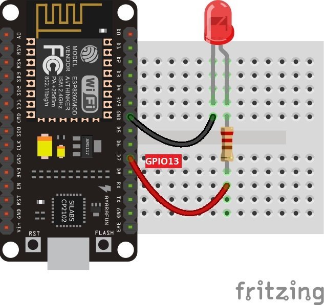
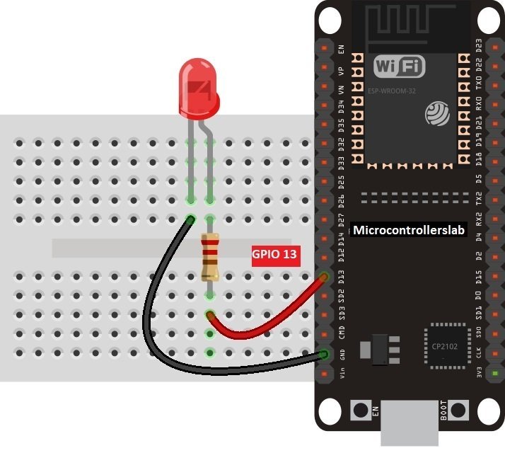
Now make connections of ESP32 and ESP8266. Connect GPIO13 of ESP32 and ESP8266 with an LED anode terminal through a 220 ohm current limiting resistor. Also, make sure to connect cathode terminal of an LED with the ground pin of ESP boards.
For ESP8266 Module, connect the components as shown in the schematic diagram below:
Similarly, for ESP32 Module connect the components as shown in the schematic diagram below:
| LED | ESP32 | ESP8266 |
|---|---|---|
| Anode (+) | GPIO13 | GPIO13 |
| Cathode(-) | GND | GND |
LED Blinking MicroPython Script
Now let’s create an LED blinking script for ESP32 and ESP8266 in Micropython. First, create an new file by clicking on new file button from sidebar in uPyCraft IDE:

Copy this file to new opened untitled window:
#hardware platform: ESP32 nd

import time
from machine import Pin
led=Pin(13,Pin.OUT)        #create LED object from pin2,Set Pin2 to output

while True:
  led.value(1)            #Set led turn on
  time.sleep(0.5)
  led.value(0)            #Set led turn off
  time.sleep(0.5)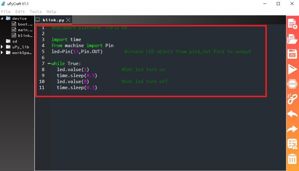
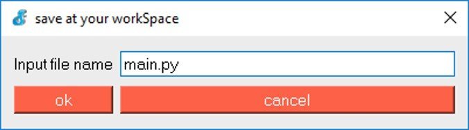
After that click on the “Save file” button to save the file on your computer. You can select any location in your computer where you want to save this file.

When you click on the “Save file” button, A new window as shown below will open. Given your file a name such as main.py and save it on your computer.
Now click on “Download and Run” to upload code to ESP32 or ESP8266. Before uploading code make sure to select boards and COM port from Tools>Board and Tools>Port menu of uPycraft IDE.
How Code Works?
In this section, we will see how codes work.
Importing MicroPython GPIO and Time Libraries
In MicroPython, a machine module contains classes of different peripherals of ESP32 and ESP8266 such as GPIO, ADC, PWM, I2C, SPI, etc. In this tutorial, we are using GPIO pins of ESP32 and ESP8266. Therefore, we will import GPIO class from a machine module. Hence, here we import the Pin class from the machine module. We can create multiple instances of the Pin class to configure different GPIO pins of ESP32 and ESP8266.
from machine import PinAdding Delays
The time module in micropython contains different methods such as delay, sleep, etc. For example, we can use a sleep() method to insert delays into our MicroPython script.
import time
Creating Instance of Pin Class
As mentioned earlier, we can create multiple objects of an “led” class which we defined above. In this line, we create an instance of the Pin object “led”. But user can give any name to an object such as led13, led_13, etc.
led=Pin(13, Pin.OUT)The Pin() class takes three paramters as shown below:
Pin(Pin_number, pin_mode, pull, value)
- First argument is a pin number to which we want to configure in different modes such as input, output, etc.
- Second argument defines the pin mode such as digital input (Pin.IN), digital output (Pin.OUT), open-drain (OPEN_DRAIN).
- Third argument specifies if we want to enable pull-up and pull-down internal resistor of a GPIO pin. These pull-up and pull-down resistors become handy when we want to use GPIO pins as a digital input pin (PULL_UP, or PULL_DOWN).
- Last argument defines the initial state of GPIO pin as either active high (1) or active low (0). But, by default, the GPIO initial state on reset is 0 (active low).
This is an infinite loop which keeps on running endlessly.
while True: //infinite loopSetting GPIO Pin State
Pin class contains a function known as value() which is used to set the state of GPIO pins. Passing 1 to this function will set the GPIO pin to an active high state. Similarly, passing 0 to this routine sets the GPIO pin to an active low state. Here, we have set the GPIO13 to an active high state by accessing a value() routine through an object “led”.
led.value(1) // LED is turned onThis gives a delay of 0.5 seconds before the Led turns off again.
time.sleep(0.5) //Delay of 0.5 secondsHere, we have set the GPIO13 to an active low state by accessing a value() routine through an object “led”.
led.value(0) //LED is turned offThis gives a delay of 0.5 seconds before the Led turns on again, therefore, producing the blinking effect.
time.sleep(0.5) //Delay of 0.5 secondsDemo
After we have written the code in the editor section. Click the Download and Run button to upload the file to your ESP32 and ESP8266 modules.

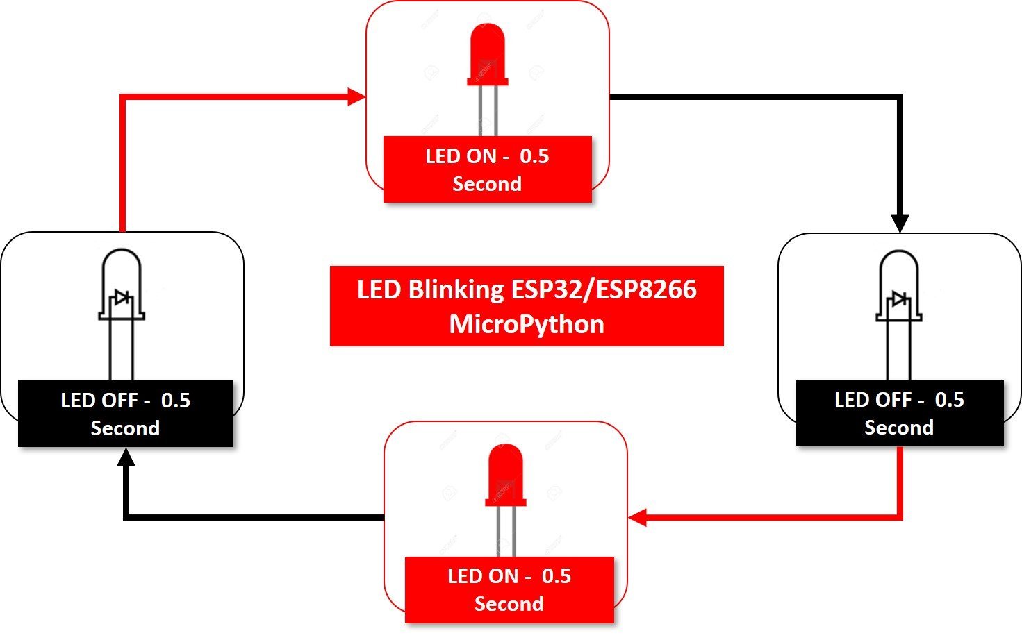
After that click the ENABLE button on ESP32/ESP8266 boards. You will see an LED blinking at a rate of one second as shown below:
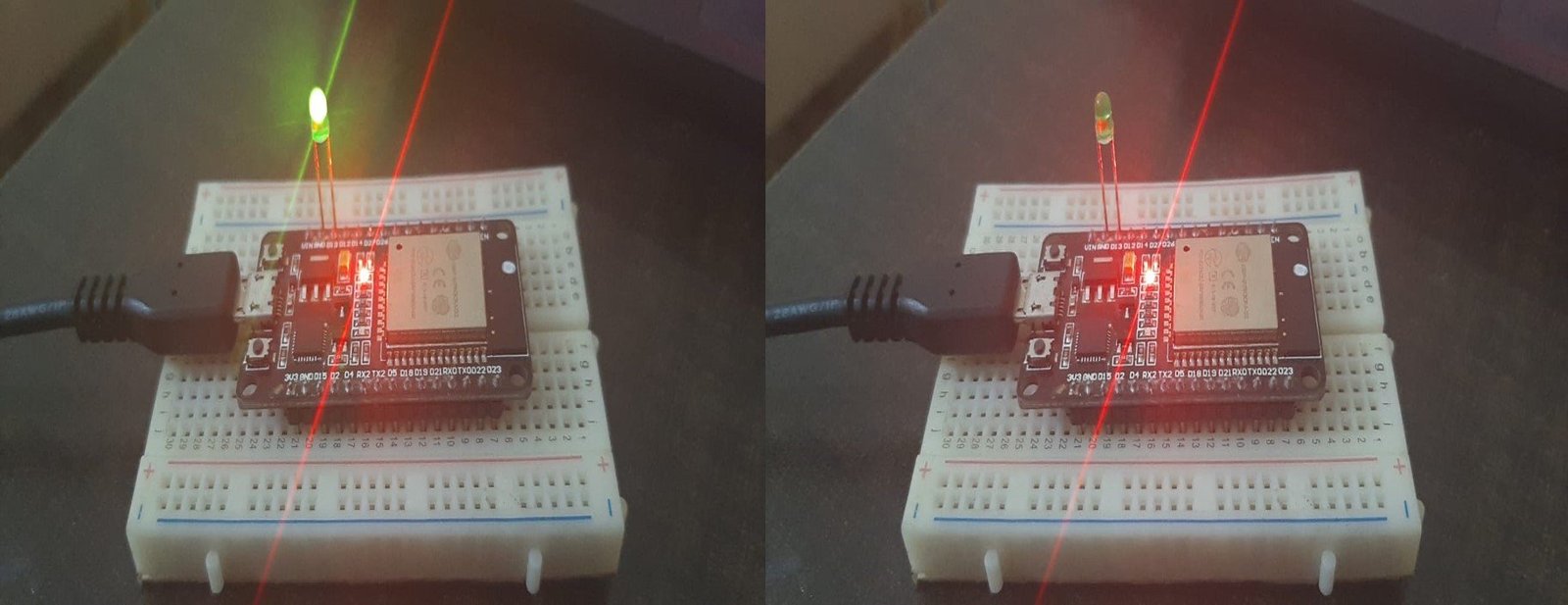
MicroPython Pin class also provides a method to set GPIO pins to active high or active low state without using any input such parameter know as led.on() and led.off. Where led is an object of a class Pin. This example shows the use of these methods.
#hardware platform: ESP32 nd

import time
from machine import Pin
led=Pin(13,Pin.OUT)        #create LED object from pin2,Set Pin2 to output

while True:
  led.on()            #Set led turn on
  time.sleep(0.5)
  led.off()            #Set led turn off
  time.sleep(0.5)
Chasing Three LEDs using ESP32 and ESP8266
Now we will learn how to perform a chasing effect using three leds using the given modules in MicroPython. In order to perform this project we need the following equipment:
- Breadboard
- Three LEDs
- Three 300 ohm resistors
- Connecting Wires
- ESP 8266/ ESP 32 board
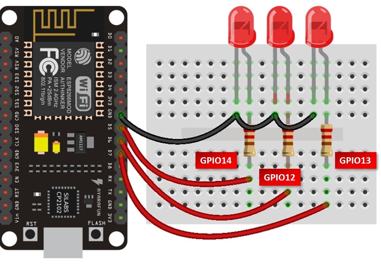
For ESP8266 Module, connect the components as shown in the schematic diagram below:
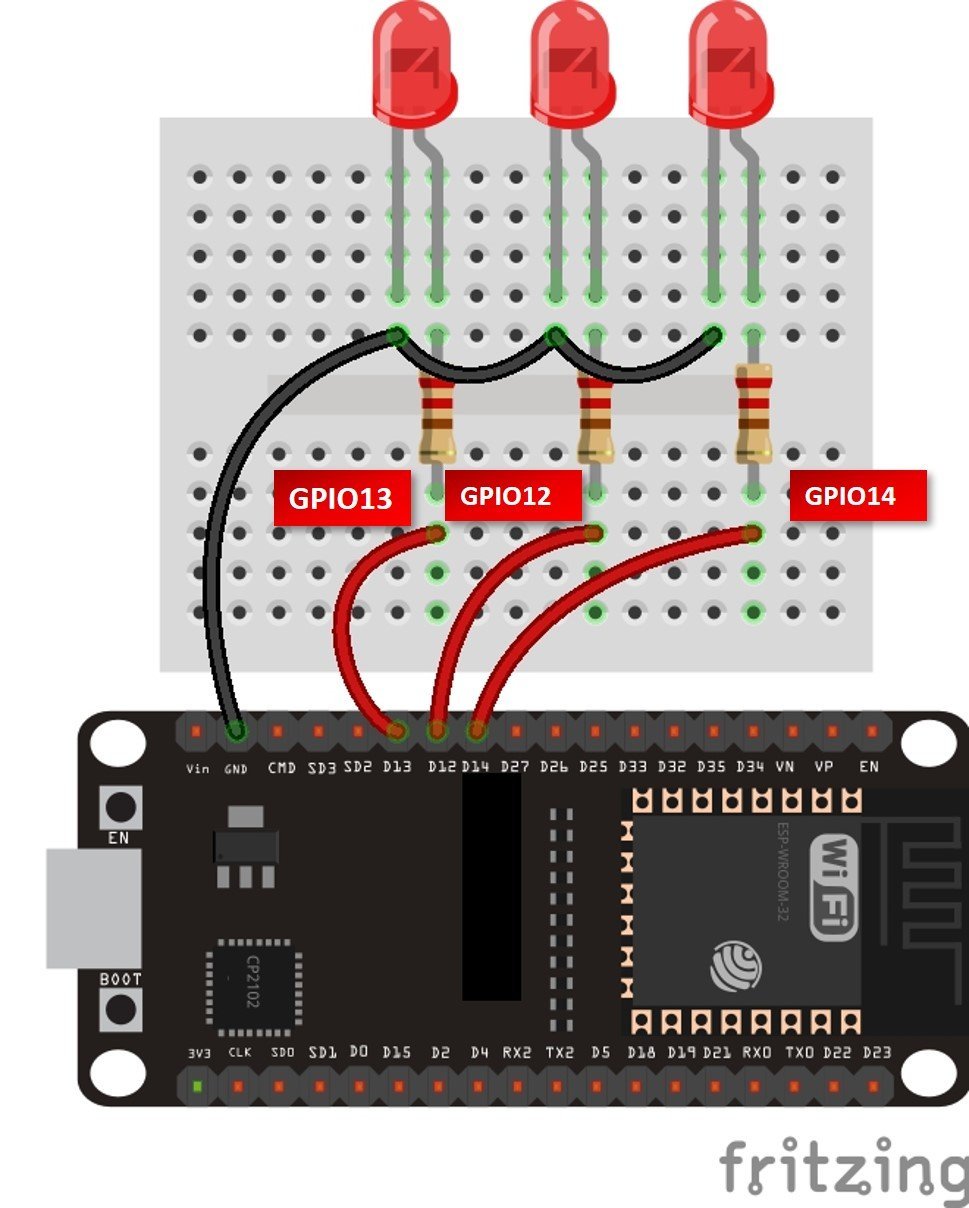
For ESP32 Module, connect the components as shown in the schematic diagram below:
LED Chaser Script MicroPython
from machine import Pin
from time import sleep

led_13 = Pin(13, Pin.OUT)
led_14 = Pin(14, Pin.OUT)
led_12 = Pin(12, Pin.OUT)


while True:
  led_12.value(0)
  led_13.value(1)
  led_14.value(0)
  sleep(0.5)
  led_12.value(1)
  led_13.value(0)
  led_14.value(0)
  sleep(0.5)
  led_12.value(0)
  led_13.value(0)
  led_14.value(1)
  sleep(0.5)
To see the demo of the above code, make sure your MicroPython is flashed to the ESP development board.
In summary, in this tutorial, we have learned to use GPIO pins of ESP32 and ESP8266 in digital output mode using MicroPython.