In this tutorial, we will learn how to use GPIO pins of the ESP32 devkit with LED blinking examples using Arduino IDE. Whenever any beginner starts learning about any microcontroller-based development board, Experts always recommend beginners to start with an LED blinking example which is also known as a light emitting diode. LED blinking examples use general-purpose input output pins to turn on and turn off the LED. By learning how to control GPIO pins, you will be able to use GPIO pins of ESP32 board for other applications like LCD interfacing, keypad interfacing, and other embedded system projects.
ESP32 LED Blinking Tutorial Prerequisites
Let’s start with the basic introduction of general-purpose input-output pins of the ESP32 Devkit. You can use any ESP32 development board you want until it has an ESP-WROOM-32 chip on it. Also, the concepts used in this article will remain applicable to other types of ESP32 boards. For more features of this board, you can go through this tutorial:
We will be using Arduino IDE to program ESP32. So if you don’t know how to install a library of this IOT board you can check this tutorial:
ESP32 GPIO Pins
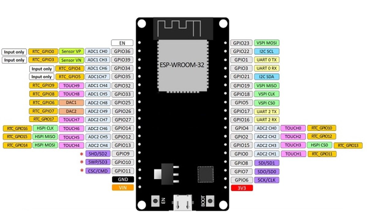
In the market, various ESP32 dev kits are available, and the one used in this tutorial has 36 GPIO pins, although not all of them can be utilized as digital output pins. Out of a total of 30 pins, 24 pins can function as both digital input and output, while the remaining six pins (GPIO34, GPIO35, GPIO36, GPIO37, GPIO38, GPIO39) can only serve as digital input pins. Nonetheless, the 24 pins available for digital output are sufficient to power LED, relay, seven-segment displays, liquid crystal display, and other actuators. Therefore, any of the thirty pins can be utilized for this purpose.
Note: GPIO6 to GPIO 11 are not exposed to pinout of ESP32 dev kit which we are using in this tutorial. Because these pins are internally connected to the integrated SPI flash on the ESP-WROOM-32 chip.
Do you want to learn the difference between a sensor and an actuator? Check here. For more information about the GPIO pins of the ESP32 development board, check this article:
Now that I believed you have already installed ESP32 in Arduino IDE You have also gone through the article on ESP32 pinout. Now let’s see how to blink an LED using ESP32 and Arduino IDE.
LED Blinking Example Using ESP32
As I mentioned earlier in ESP32, we have can use 30 pins as a digital output pin. Now let’s select one pin and used it to turn on and turn off LED with some delay.
In this example, we will control an LED with GPIO22 of ESP32. That means we will learn to use GPIO pins as digital output pins. We connect an LED to GPIO22 through a current limiting resistor of 220 ohms. This ESP32 LED blinking example works as mentioned below:
- RED LED Turns on for one second which means GPIO22 goes to an active high state
- In the next step, the LED turns off for one second which means GPIO22 goes to an active low state
- The above two steps keep repeating as shown below:

LED Blinking Connection Diagram
As you can in the above pinout diagram of ESP32, we have a total of 36 GPIO pins, but we will be using GPIO22 as a digital output pin. On different boards, these pins can be located at different locations. Therefore, you need to check its datasheet before using pin number in programming which I will explain in the programming part of this article.
Now check the schematic and make it on your breadboard as shown below:

Now make the circuit connection according to the above circuit diagram on the bread board.
- Connect GPIO22 with the anode or positive pin of the LED. Positive pin is usually round edge.
- Connected other end of the LED with ground through 330 ohm resistor. Resistor is used as a current limiting resistor.
- Each pin can provide a maximum of 10mA current. So current limiting resistor is used to limit current not crossing this limit.
- If you want to use GPIO pins to drive any other device which has a higher current requirement, you should connect a transistor in between or current driver integrated circuit like ULN2003 relay driver circuit IC.
ESP32 GPIO Pins Arduino Functions
To write code for LED blinking using ESP32, first, you need to understand three main functions used in Arduino IDE to control general purpose input output pins. If you have already used Arduino IDE for Arduino or esp8266 programming, you will be already familiar with these functions :
- pinMode() : This function is used to select input output pin mode either as a input or output. First argument to this function is pin number to which you want to declare either as a input or output. Second argument to this function is in which direction you want to use a digital pin. For example, if we write pinMode(22, OUPUT) , it will declare pin number 22 as a digital output pin.
- digitalWrite(pin_number, LOGIC_HIGH_LOW) : This function is used to control digital output pin. First argument is a pin number and second value to this function is logic state ‘HIGH’ or ‘LOW’. For example, if you write digitalWrite(22, HIGH), it will make pin number 22 logic HIGH or 3.3 volt and if you write digitalWrite(22, LOW), it will make digital output pin 22 LOW or you will get zero volt at the output pin.
- delay(value) : This function is used to generate delay in mili seconds. If you want to add a delay of one second between turning on and turning off a LED, you will use this state delay(1000).
- setup( ) : In Arduino IDE, setup function is used for declaration or initialization. A pinMode function is used for declaration of digital pins. So it will be defined inside setup function. It will become more clear when you see the example code at the end of this article.
- Loop( ) : In Arduino IDE, loop function is like a main function in c programming. In c programming whenever, you want to perform certain tasks again and again, we use those c statements inside the loop. Similarly, we use loop function in Arduino IDE to perform certain tasks again and again.
Arduino Code
This code is used to blink an LED connected with pin number 22 with a delay of one second.
void setup()
{
pinMode(22, OUTPUT); // Set GPIO22 as digital output pin
}

void loop()
{
digitalWrite(22, HIGH); // Set GPIO22 active high
delay(1000);  // delay of one second
digitalWrite(22, LOW); // Set GPIO22 active low
delay(1000); // delay of one second
}
The code consists of two functions: setup() and loop().
The setup() function is called once when the board is first powered on or reset. It sets the mode of GPIO22 to an output pin.
The loop() function is called repeatedly after setup() and contains the main logic of the program.
In loop(), the digital pin 22 is turned on (set to a HIGH state) using the digitalWrite() function. Then a delay of 1000 milliseconds (1 second) is introduced using the delay() function. After the delay, the pin 22 is turned off (set to a LOW state) using digitalWrite() function again. Another delay of 1000 milliseconds is introduced. This process of turning the pin on and off is repeated indefinitely in a loop.
digitalWrite(22, HIGH); // Set GPIO22 active high
delay(1000);  // delay of one second
digitalWrite(22, LOW); // Set GPIO22 active low
delay(1000); // delay of one second
In summary, this code turns on and off a digital pin (GPIO22) on an Arduino board with a delay of 1 second between each state change. This can be used for various purposes such as blinking an LED connected to the pin, controlling a relay, or sending signals to other devices.
ESP32 LED Blinking Demo
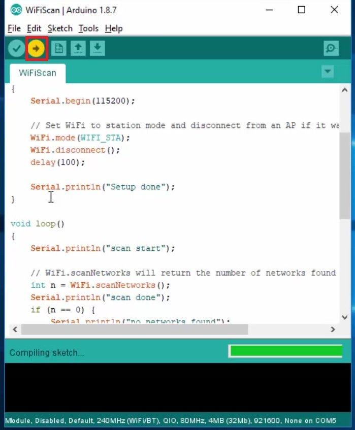
Now to run this example of LED blinking using ESP32, simply copy this code to Arduino IDE and compile the code.
After compiling code, click on the upload button to upload the code to the ESP32 devkit.
Before uploading the code, make sure you have selected the board and COM pin to which your ESP32 board is connected.
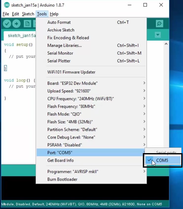
If you do not see this board in the tools>port option, you need to install the driver for this board, you can download and install drivers from this link.
Go to tools>Boards and select ESP32

Go to tools>Upload speed and choose 115200
Also, select Flash Frequency of 80Mhz from the tools options.
Now click on the upload button.
After that, you will see LED will be blinking with a delay of one second.
It is a getting started tutorial with ESP32. To explore more tutorials and projects follow these guides:
your notes on the Arduino /esp32 functions are clear. Since you introducing coding how about including a paragraph on the use and positioning of curly brackets?
Hi,
on the line “digitalWrite(22 LOW);”, there is a comma missing…
It should be “digitalWrite(22, LOW);”
Greatings
yes, thanks for the correction
which GPIO’S to be used for 8 led including creating a access point of esp32..
how to use multi file code in esp32?
In The Blink Code. I want to change the pin Numbers .How would I do That?
just change the pin number which you want to use inside pinMode() function.
Running 4 LED’S on a ESP32 do not work! Below is the programm:
//
// in this programm four LED’S are connected tp port GPIO23,
// GPIO22, GPIO21, and GPI19 of the ESP23-DEVKITC. THe program
// turns on the LED’S ina rotating pattern. THe ON and OFF times
// are chosen as 500 ms and 100ms so that a nice rotating effect is displayed
//
int LEDs[] = {23,22,21,19};
#define ON HIGH
#define OFF LOW
//
//set GPIO ins 23,22,21,19 as outputs and turn off the LEDs
//to start with
//
void setup()
{
unsigned int i;
for(i=0; i < 3; i++)
{
pinMode(LEDs[i],OUTPUT);
delay(500);
digitalWrite(LEDs[i],OFF);
delay(500);
}
}
//
// Turn ON/OFF the LEDs in a rotating pattern
//
void loop()
{
unsigned int j;
for(j=0; j < 3; j++)
{
digitalWrite(LEDs[j],ON);
delay(500);
digitalWrite(LEDs[j],OFF);
delay(100);
}
}
Led on port 23, 21 works OK, which means they blink
Led on port 21 works also!
But the LED on port 19 do not work.
So can anyone help me out, what is happen!
I treyed it with different Ports, but the result is everytimethe same. Always 3 LED'S works, but not the 4.
With best regards,
Reinhold
Your array has 4 positions: int LEDs[] = {23,22,21,19}; but your for loop is only indexing the first 3: for(i=0; i < 3; i++). This will hit index 0, 1, & 2 since index 3 is not less than 3
Change your for loop to be < 4: for(i=0; i < 4; i++)
OR Change your for loop : for(i=0; i <=3; i++)
Hi, if you still have this problem and you haven’t solved it yourself, put one = after the > signs
Ali from “”Esfahan””
After running the Blink example, how do you get it to stop blinking?