In this tutorial, we will guide you through the process of connecting an I2C LCD to the ESP32 board. This comprehensive guide is applicable to the ESP8266 NodeMCU as well. The I2C LCD is a versatile 16×2 device, providing you with the capability to display 16 columns by two rows of alphanumeric characters. Moreover, you can even create custom characters to enhance your displays with basic graphics or bar graphs. Powered by the efficient hd44780 controller, the LCD comes equipped with an integrated I2C circuit, allowing for effortless integration with the ESP32 board. Gone are the days of dealing with multiple pins, as this I2C LCD streamlines the process for you.
Let’s dive into the step-by-step instructions and get your LCD connected and functional in no time! You can find more information about the pins by going to this article:
Recommended Components
The following components are used in this project or are helpful for building it with the ESP32.
| Component | How it’s used in this project | Buy on Amazon |
|---|---|---|
| ESP32 Development Board (DevKit V1) | Drives the I2C LCD and runs the display example. | Check Price |
| ESP8266 NodeMCU (ESP-12E) | An alternative Wi-Fi board; this tutorial works on the ESP8266 NodeMCU as well. | Check Price |
| Micro USB Cable | Connects the board to your computer to upload the sketch and power it. | Check Price |
| Breadboard | Holds the board and components together while you wire up the project. | Check Price |
| Jumper Wires | Make the connections between the board and any external parts. | Check Price |
| 16×2 I2C LCD | The I2C character display you interface with the board in this tutorial. | Check Price |
As an Amazon Associate we earn from qualifying purchases. Prices and availability are accurate as of the date/time indicated and are subject to change.
Why I2C LCD is a Good Choice?
To directly connect this LCD to an ESP32 board, we would typically have to utilize eight general-purpose input/output (GPIO) pins of the ESP32. However, this approach would unnecessarily consume GPIO pins. A more optimal solution is to use an I2C LCD instead of a traditional 16×2 LCD. In this tutorial, we will be using a 16×2 I2C LCD, but LCDs of any size would work similarly, as we will explore in this tutorial.
The advantage of using an I2C LCD is that we only need to employ two pins of the ESP32 to establish a connection with the display.
We have a similar guide with Arduino:
I2C LCD Pinout
So now let’s start with the pinout of this display. This display has four pins:
- Ground pin
- Vcc pin
- SDA
- SCL
To connect the LCD with the ESP32 development board, follow these steps:
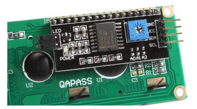
- Locate the back side of the liquid crystal display (LCD) module. Here, you will find a variable resistor.
- The purpose of this variable resistor is to adjust the brightness of the LCD.
- This potentiometer becomes particularly useful when using the display module in varying light conditions.
By utilizing this built-in feature, you can easily modify the brightness of the LCD display to ensure optimal visibility at all times.
Interfacing I2C LCD with ESP32
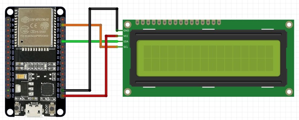
Now we will see the wiring diagram of I2C LCD with the ESP32 development board. The wiring diagram is straightforward. We only need to use two GPIO pins of ESP32 Devkit with this display as you can see in the picture shown here.
In this circuit, we are using the default I2C communication pins of the ESP32 board. In this board, GPIO22 is the default SCL pin, and GPIO21 is the default SDA pin for I2C communication. So you need to connect GPIO22 with SCL pin of LCD and GPIO21 with SDA pin of liquid crystal display. You can also check this table for wiring connections.
| ESP32 Development Board | I2C LCD |
|---|---|
| GPIO22 | SCL |
| GPIO21 | SDA |
| GROUND | GND |
| 3.3 VOLT / VCC PIN | VIN |
Installing I2C LCD Library in Arduino IDE
So we will move to the coding part. Before writing code, we need to prepare the Arduino IDE to write code. The followings are the essentials for this tutorial:
- You should know ESP32 development board; you can check this introduction to esp32 development board tutorial.
- You have to install ESP32 library in Arduino IDE, so you check this post if you have not installed it earlier: How to install ESP32 in Arduino IDE?
- ESP32 pinout which pin you should use?
After installing ESP32 in Arduino IDE, We will introduce the library of I2C LCD in Arduino IDE. This library is not available in the compiler. So we need to install an external library. There are many I2C LCD libraries available. You can use different libraries if you want. But in this tutorial, we are using the library developed by johnrickman. Now add this library by following these steps:
- Go to this link and download the I2C LCD library.
- The file which you download in the last step will be a compressed or zip file. Now unzip this file.
- After unzipping the file, you will get a folder with the name of LiquidCrystal_I2C-master.
- Rename this folder
LiquidCrystal_I2C-masterto LiquidCrystal_I2C. - Now close the Arduino software, if you have already opened it.
- Now copy this folder inside the library folder of your Arduino IDE.
- Now open your Arduino software. Your library will be included successfully.
Till now you have successfully installed the library and made the circuit diagram.
Getting I2C LCD Address
When you connect your I2C display with the ESP32 board, you need to check its address. Because every I2C device has an address associated with it. For many devices of I2C LCD, the default address is 0x27 where “0x” shows the hex format of the numbers. But the address can be different for some cases. This address depends on the position of pads A0, A1, and A2 on the I2C controller on this device. As you can see in this picture, we have three soldering pads, so we can have 8 different values of the address depending on the connections of the pads.
| Pad A0 | Pad A1 | Pad A2 | HEX Address |
|---|---|---|---|
1 | 1 | 1 | 0x27 |
0 | 1 | 1 | 0x26 |
1 | 0 | 1 | 0x25 |
0 | 0 | 1 | 0x24 |
1 | 1 | 0 | 0x23 |
0 | 1 | 0 | 0x22 |
1 | 0 | 0 | 0x21 |
0 | 0 | 0 | 0x20 |
But you don’t need to worry about the internal connections of this device; we will use the code given below to check the address of the controller. Now copy this code and upload it to your board.
#include <Wire.h> // This library includes I2C communication functions

void setup() {
Wire.begin();
Serial.begin(115200);
Serial.println("ESP32 scanning for I2C devices");
}

void loop() {
byte error_i2c, address_i2c;
int I2C_Devices;
Serial.println("Scanning started");
I2C_Devices = 0;
for(address_i2c = 1; address_i2c < 127; address_i2c++ )
{
Wire.beginTransmission(address_i2c);
error_i2c = Wire.endTransmission();
if (error_i2c == 0) {
Serial.print("I2C device found at address_i2c 0x");
if (address_i2c<16)
{
Serial.print("0");
}
Serial.println(address_i2c,HEX);
I2C_Devices++;
}
else if (error_i2c==4)
{
Serial.print("Unknow error_i2c at address_i2c 0x");
if (address_i2c<16)
{
Serial.print("0");
}
Serial.println(address_i2c,HEX);
}
}
if (I2C_Devices == 0)
{
Serial.println("No I2C device connected \n");
}
else {
Serial.println("done I2C device searching\n");
}
delay(2000);
}
This code will search for devices connected with GPIO pins 22 and 21 and display its result on the serial monitor. After connecting the device with the ESP32 board properly, you will get this message on the serial monitor. This message shows the address of I2C liquid crystal display which is 0x27. You will most likely get the same address for LCD with 16 columns and 2 rows.
Displaying Text on I2C LCD using ESP32
Now we will come to the main part of this tutorial. In this section, we will show a static message on the screen.
#include <LiquidCrystal_I2C.h>
int totalColumns = 16;
int totalRows = 2;
LiquidCrystal_I2C lcd(0x27, totalColumns, totalRows);
void setup(){
lcd.init();
lcd.backlight(); // use to turn on and turn off LCD back light
}
void loop()
{
lcd.setCursor(0, 0);
lcd.print("Microcontrollerslab");
lcd.setCursor(0,1);
lcd.print("I2C LCD tutorial");
delay(1000);
lcd.clear();
lcd.setCursor(0, 0);
lcd.print("Static text");
delay(1000);
lcd.setCursor(0,1);
lcd.print("I2C LCD tutorial");
delay(1000);
lcd.clear();
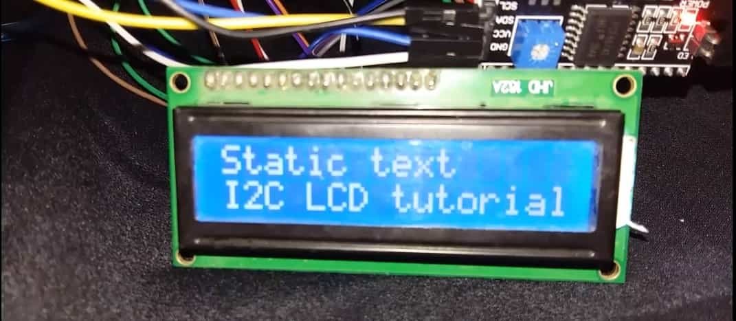
}This code will display the message “Microcontrollerslab” in the first row and “I2C LCD tutorial” in the second row for one second. After that, it will clear the LCD and displays “Static text” in the first row and “I2C LCD tutorial” in the second row as shown below.
How Code works?
Now we will see the working of code. This line will add the library in the code.
#include <LiquidCrystal_I2C.h>These two variables define the name of the total number of rows and columns of the display which in our case is 16×2. If you want to use the screen of any other size, you need to need to change the number here accordingly, for example, 20×4 display.
int totalColumns = 16;
int totalRows = 2;
This line is used to initialize the library with the address of LCD, the total number of columns and rows. The first argument to this function is an address which we have found in the last example. Second and thirds arguments are the size in terms of the number of columns and number of rows.
LiquidCrystal_I2C lcd(0x27, totalColumns, totalRows);Inside the step(), we first initialized the LCD with above-mentioned parameters.
lcd.init();This backlight() function is used to turn on or turn off the backlight. Every LCD has a backlight built-in inside it, so you can control it through this function.
lcd.backlight();In loop() part, code is used to display messages and also to clear the message for LCD. To display anything text on LCD, first, you need to set the cursor position. Cursor position defines where you want to display the text. The setCursor() function is used to set the position. For example, if you want to set the cursor to the first row and first column, you will use this function like this:
lcd.setCursor(0,0);If you want to set the cursor to the first column and second row, you will use this function like this:
lcd.setCursor(0,1);First values inside this function define the column number and the second value defines the row number. So inside the loop(), first we set the cursor to the first row and the second column. After that, lcd.print() will display the message “microcontrollerslab” in the first row.
lcd.setCursor(0, 0);
lcd.print("Microcontrollerslab");
Similarly, these two lines will set the cursor to the second row and display the text “I2C LCD tutorial” on the second row. For one second same text will be displayed in the first and second row. The delay() is used to add the delay of one second.
lcd.setCursor(0,1);
lcd.print("I2C LCD tutorial");
delay(1000);
After waiting for one second, clear() will erase the text.
lcd.clear();Now the other section of the code also works the same way.
lcd.setCursor(0, 0);    // move cursor to starting position
lcd.print("Static text");  // display text " Static text"
lcd.setCursor(0,1);       // move the curos to second row
lcd.print("I2C LCD tutorial");   //display a string
delay(1000);               //  add delay of 1 second
lcd.clear();                 // clear the screen
Demonstration
To see the demonstration of this project, upload the code to the respective ESP boards. But, before uploading code, make sure to select the ESP32 Dev Module or NodeMCU 1.0 from Tools > Board and also select the correct COM port to which the board is connected from Tools > Port.
Once the code is uploaded to the board, adjust the brightness of the display through the potentiometer until the LCD starts displaying the messages:
Display Scrolling Text on I2C LCD using ESP32
Open your Arduino IDE and go to File > New. A new file will open. Copy the code given below in that file and save it.
In this section, we will display a scrolling message on the screen.
#include <LiquidCrystal_I2C.h>

int totalColumns = 16;
int totalRows = 2;

LiquidCrystal_I2C lcd(0x27, totalColumns, totalRows);

String staticMessage = "I2C LCD Tutorial";
String scrollingMessage = "Welcome to Microcontrollerslab! This is a scrolling message.";

void scrollMessage(int row, String message, int delayTime, int totalColumns) {
  for (int i=0; i < totalColumns; i++) {
    message = " " + message;
  }
  message = message + " ";
  for (int position = 0; position < message.length(); position++) {
    lcd.setCursor(0, row);
    lcd.print(message.substring(position, position + totalColumns));
    delay(delayTime);
  }
}

void setup(){
  lcd.init();
  lcd.backlight();
}

void loop(){
  lcd.setCursor(0, 0);
  lcd.print(staticMessage);
  scrollMessage(1, scrollingMessage, 250, totalColumns);
}
How the Code Works?
This line will add the library in the code.
#include <LiquidCrystal_I2C.h>These two variables define the name of the total number of rows and columns of the display which in our case is 16×2. If you want to use the screen of any other size, you need to need to change the number here accordingly, for example, 20×4 display.
int totalColumns = 16;
int totalRows = 2;
This line is used to initialize the library with the address of LCD, the total number of columns and rows. The first argument to this function is an address which we have found in the last example. Second and thirds arguments are the size in terms of the number of columns and number of rows.
LiquidCrystal_I2C lcd(0x27, totalColumns, totalRows);Next, we will define two string variables that will hold the static and the scrolling message that we will display on the LCD.
String staticMessage = "I2C LCD Tutorial";
String scrollingMessage = "Welcome to Microcontrollerslab! This is a scrolling message.";
scrollMessage()
The user defined scrollMessage() function will be used to scroll a text on the LCD. It takes in four arguments. The first is the row where we will display our message. The second is the message that will be displayed. The third is the delay time that will control the speed of the scrolling text. Lastly, the fourth argument is the total columns of the LCD.
void scrollMessage(int row, String message, int delayTime, int totalColumns) {
  for (int i=0; i < totalColumns; i++) {
    message = " " + message;
  }
  message = message + " ";
  for (int position = 0; position < message.length(); position++) {
    lcd.setCursor(0, row);
    lcd.print(message.substring(position, position + totalColumns));
    delay(delayTime);
  }
}
setup()
Inside the setup(), we first initialized the LCD with above-mentioned parameters.
lcd.init();This backlight() function is used to turn on or turn off the backlight. Every LCD has a backlight built-in inside it, so you can control it through this function.
lcd.backlight();loop()
In loop() part, we will first set the cursor and then print the static message by using lcd.print() and pass the staticMessage as an argyment inside it. Then call the scrollMessage() function and pass ‘1’ as the starting row, ‘scrollingMessage’ as the message to be displayed, 250ms delay time and specify the ‘totalColumns’ of the LCD.
void loop(){
  lcd.setCursor(0, 0);
  lcd.print(staticMessage);
  scrollMessage(1, scrollingMessage, 250, totalColumns);
}
Demonstration
To see the demonstration of this project, upload the code to the respective ESP boards. But, before uploading code, make sure to select the ESP32 Dev Module or NodeMCU 1.0 from Tools > Board and also select the correct COM port to which the board is connected from Tools > Port.
Once the code is uploaded to the board, adjust the brightness of the display through the potentiometer until the LCD starts displaying the messages:
Display Custom Characters on I2C LCD using ESP32 and ESP8266
In this section, we will display custom characters on the LCD screen.
For our 16×2 LCD display that we are using, we have the option to display custom characters as well. In this particular LCD, each block consists of 5×8 pixels. These can be used to display custom characters by setting the state of each pixel by inside a byte variable.
There is a very simple way to generate the byte variable of your own custom character. Head over to the following custom character generator: (Custom Character Generator for HD44780 LCD Modules).
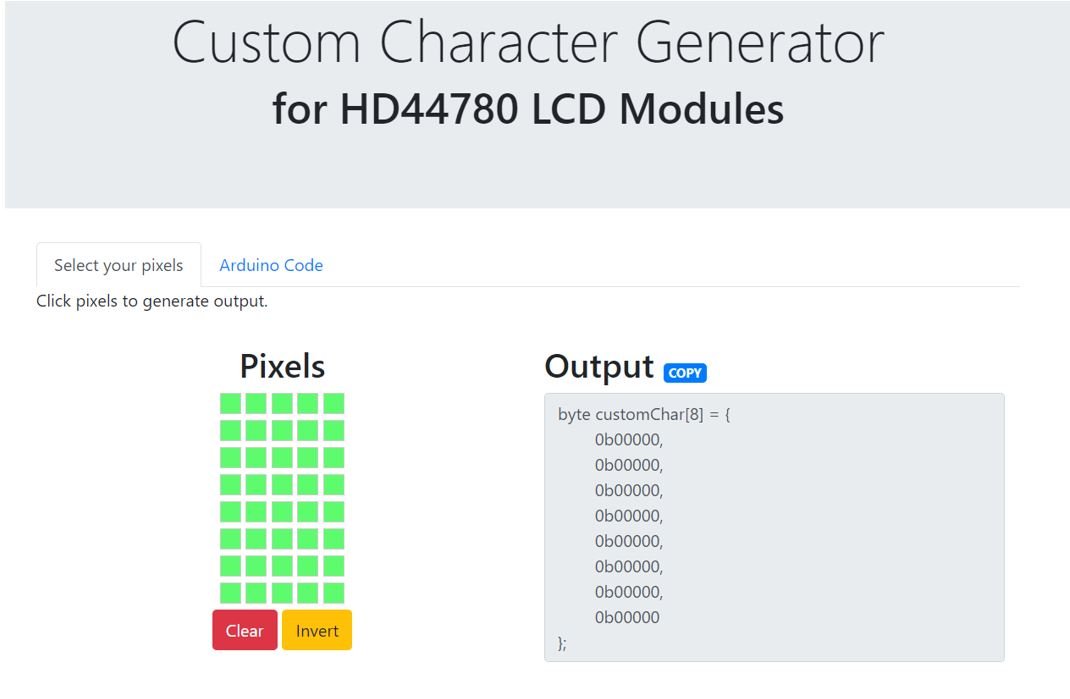
Specify the custom character you want to display by clicking the pixels in the 5×8 pixel block and the corresponding byte variable will be generated.
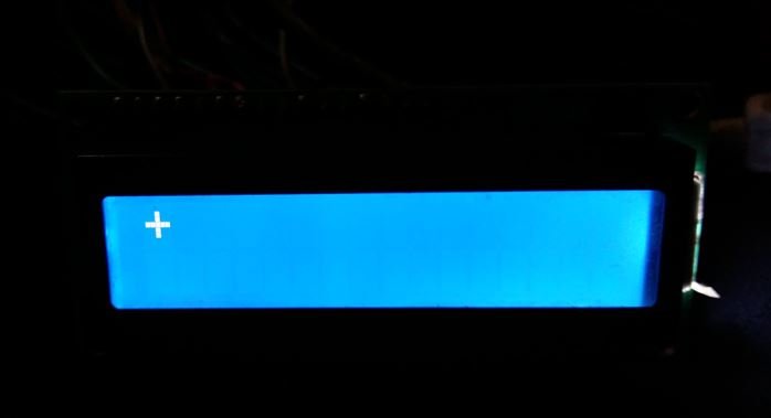
In our case, we will display a ‘+’ character on the screen. This is the byte variable that we will use in our program code to display this particular character on the LCD.

Arduino Sketch
Open your Arduino IDE and go to File > New. A new file will open. Copy the code given below in that file and save it.
In this sketch, we will display a custom character on the LCD.
#include <LiquidCrystal_I2C.h>

int totalColumns = 16;
int totalRows = 2;

LiquidCrystal_I2C lcd(0x27, totalColumns, totalRows);

byte customChar[8] = {
  0b00000,
  0b00100,
  0b00100,
  0b11111,
  0b00100,
  0b00100,
  0b00000,
  0b00000
};

void setup()
{
  lcd.init();
  lcd.backlight();
  lcd.createChar(0, customChar);
}

void loop()
{
 lcd.setCursor(0, 0);
 lcd.write(0);
}
How the Code Works?
Include the byte variable that we obtained from the custom character generator. This is the byte variable for a ‘+’ character.
byte customChar[8] = {
  0b00000,
  0b00100,
  0b00100,
  0b11111,
  0b00100,
  0b00100,
  0b00000,
  0b00000
};
Inside the setup() function we will create the custom character by calling lcd.createChar() and pass a number between 0-7 (allocated location) and the byte variable as parameters inside it.
lcd.createChar(0, customChar);
Inside the loop() function we will display our character using lcd.write() and pass the allocated location as the parameter.
void loop()
{
 lcd.setCursor(0, 0);
 lcd.write(0);
}
Demonstration
To see the demonstration of this project, upload the code to the respective ESP boards. But, before uploading code, make sure to select the ESP32 Dev Module or NodeMCU 1.0 from Tools > Board and also select the correct COM port to which the board is connected from Tools > Port.
Once the code is uploaded to the board, adjust the brightness of the display through the potentiometer until the LCD starts displaying the character:
I2C LCD Advantages
I2C (Inter-Integrated Circuit) 16×2 LCD modules offer several advantages over non-I2C (parallel) LCD modules. Here are some of the key advantages:
- Reduced Pin Count: I2C LCD modules require only two communication pins (SDA and SCL) to interface with the microcontroller, whereas non-I2C LCDs require a larger number of data and control pins (typically 4 or 8 data pins and at least 3 control pins). This reduction in pin count can be beneficial, especially when the microcontroller has limited available pins.
- Simplified Wiring: With fewer pins to connect, the wiring complexity is reduced, making the circuit design and assembly easier and more organized.
- Less I/O Usage: I2C LCD modules use I2C protocol, which is a serial communication protocol. Serial communication requires fewer I/O pins compared to parallel communication, which is used in non-I2C LCDs. This is particularly useful for microcontrollers with limited I/O resources.
- I2C Addressing: I2C devices, including I2C LCDs, can be assigned unique addresses, allowing multiple I2C devices to be connected to the same I2C bus. This enables the connection of multiple I2C devices without conflict, making it easier to expand the system.
- Simplified Code: I2C communication is handled by the hardware I2C controller in the microcontroller, so the code required to interface with the LCD is often simpler and requires less overhead compared to the custom software implementation needed for non-I2C LCDs.
It’s worth noting that there are some trade-offs as well. I2C communication can be slower compared to parallel communication, especially when dealing with large amounts of data. Additionally, the availability and cost of I2C vs. non-I2C LCD modules can vary based on specific requirements and market availability. Therefore, the choice between I2C and non-I2C LCDs should be based on the specific needs and constraints of the project.
In summary:
In this tutorial, we have learned how to interface an I2C LCD with ESP32 using Arduino IDE and how to display custom characters on I2C LCD.
You may also like to check other ESP32 projects :
- Password protected ESP32 web server in Arduino IDE
- Accessing ESP32 web server from anywhere in the world
- DHT11 and DHT22 web server to display temperature and humidity values on the web page
Other I2C LCD tutorials: