In this tutorial, we will learn to interface I2C LCD with STM32 Blue Pill and program it using STM32CubeIDE and HAL libraries. Firstly, we will briefly introduce you to the I2C LCD including its pinout and connection with STM32 Blue Pill. Then we will move ahead and program our board in STMCube IDE to demonstrate some basic functionalities that we can display on the LCD.
We have similar guides for I2C LCD with other microcontrollers also:
- I2C LCD with ESP32 and ESP8266 using MicroPython
- I2C LCD interfacing with Arduino Display Scrolling Text and Custom Characters
- I2C LCD interfacing with ESP32 and ESP8266 in Arduino IDE
Recommended Components
The following components are used in this project or are helpful for getting started with STM32 Blue Pill development.
| Component | How it’s used in this project | Buy on Amazon |
|---|---|---|
| STM32F103C8T6 Blue Pill Board | The STM32 board driving the I2C LCD. | Check Price |
| ST-Link V2 Programmer | SWD programmer/debugger used to flash code onto the Blue Pill. | Check Price |
| 16×2 I2C LCD Display | The 16×2 character LCD with I2C backpack used in this project. | Check Price |
| Breadboard & Jumper Wires | For wiring the LCD to the Blue Pill. | Check Price |
As an Amazon Associate we earn from qualifying purchases. Prices and availability are accurate as of the date/time indicated and are subject to change.
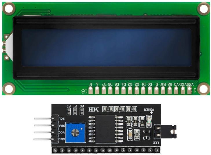
I2C LCD Introduction
The I2C LCD is a 16×2 device which means it can display 16 columns by two rows of characters. The characters are alphanumeric, but you can create custom characters for basic graphics, bar graphs that kind of thing. The LCD has the usual type of hd44780 controller, and it also has an I2C circuit connected with it which makes it easy to connect to the STM board. 16X2 LCD without I2C circuit has sixteen pins.
You can find more information about the pins by going to this article:
If we want to connect this board directly with the STM32 Blue Pill board, we have to use at least eight general-purpose input output pins of STM32 which will be a waste of GPIO pins. So the better solution is to use an I2C LCD instead of a typical 16×2 LCD. In this tutorial, we are using 16×2 I2C LCD. The advantage of using an I2C LCD is that we only need to use two pins of STM32 to connect with this display.
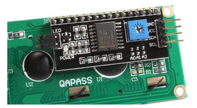
I2C LCD Pinout
So now let’s start with the pinout of this display. This display has four pins:
- Ground pin
- VCC pin
- SDA
- SCL
At the back side of this liquid crystal display, you can also see a variable resistor. This variable resistor is used to modify the brightness of the LCD. This potentiometer is very handy when you are using this display module in different light conditions.
Interfacing I2C LCD with STM32 Blue Pill
For this project we will require the following components:
- STM32 Blue Pill
- I2C LCD
- Connecting Wires
- Breadboard
Connect the components as shown in the schematic diagram below:
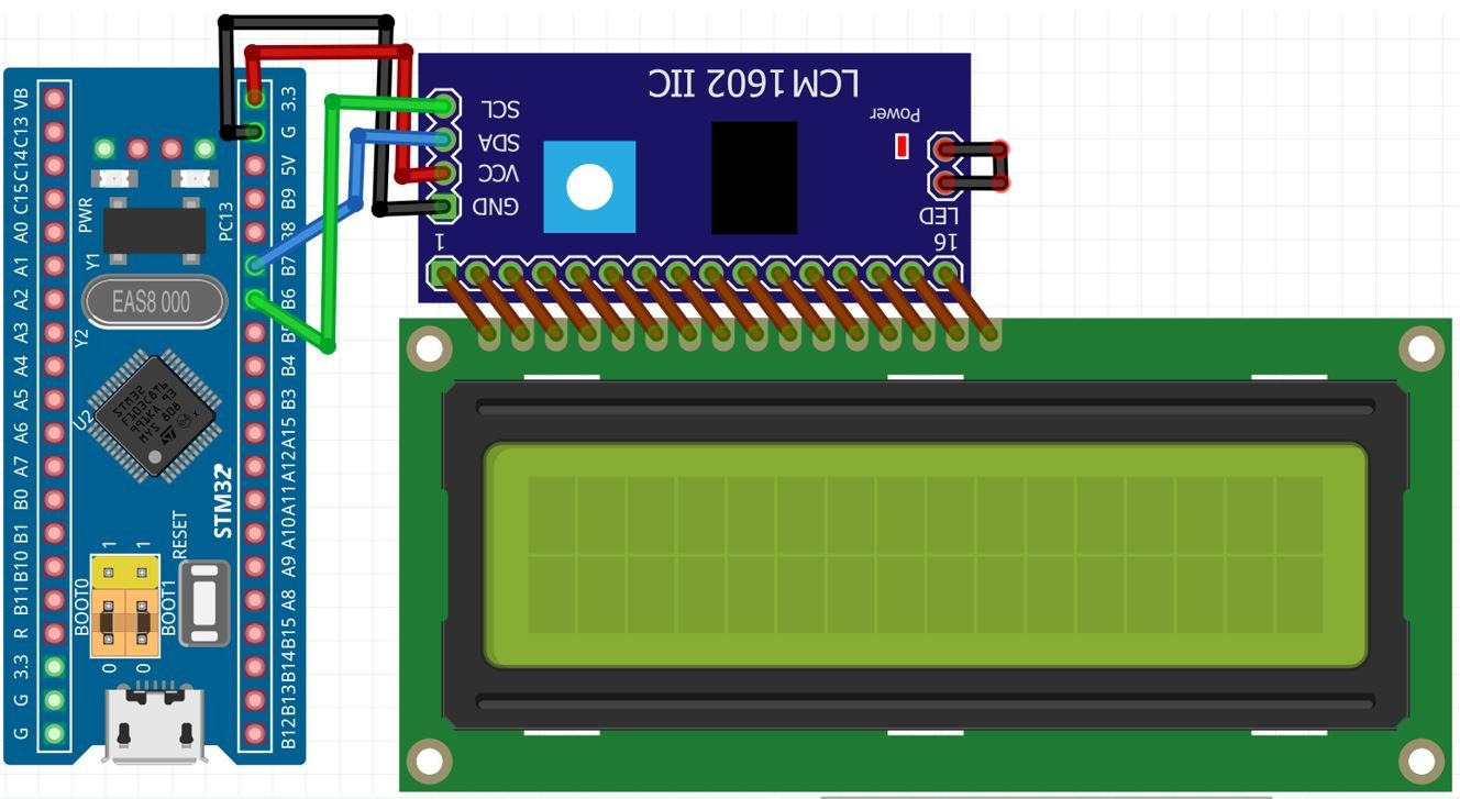
Follow the schematic diagram below to connect all the devices together. We will power the I2C LCD with 3.3V pin of STM32. The SCL and SDA pins of I2C LCD will be connected with the I2C1 SDA and SCL pins of the STM32 board respectively. PB7 is I2C1_SDA pin and PB6 is I2C1_SCL pin. Moreover, the grounds will be in common.
| STM32 Blue Pill | I2C LCD |
|---|---|
| PB6 | SCL |
| PB7 | SDA |
| GND | GND |
| 3.3V | VCC |
STM32 Blue Pill I2C LCD Code
We will use STM32Cube IDE to program our STM32 board. Open the IDE and head over to a new project.
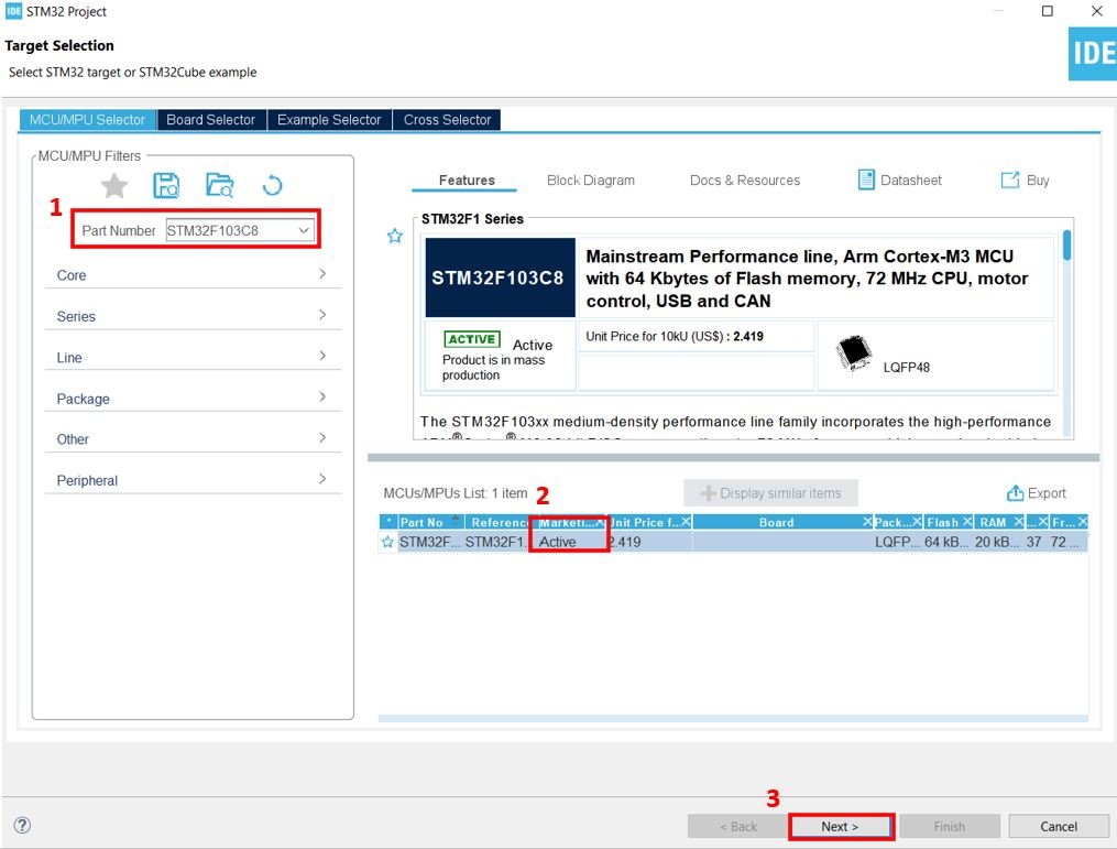
Then for the target selection, specify the STM32 Blue Pill board number. After that click on any column as shown in the picture below. Then click the ‘Next’ button.
Specify the name of your project then click ‘Finish’ to complete the setup of your project.
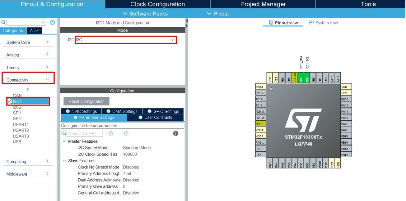
Now head over to Connectivity > I2C1. Select the I2C mode as ‘I2C.’
Now go to System Core > RCC then select ‘Crystal/Ceramic Resonator’ in from the High Speed Clock feature.
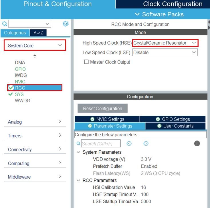
Now we have enabled the RCC external clock source.
Clock Configuration
Next, go to the Clock Configuration found at the top. This will open the following window. Here we will select the clock frequency.
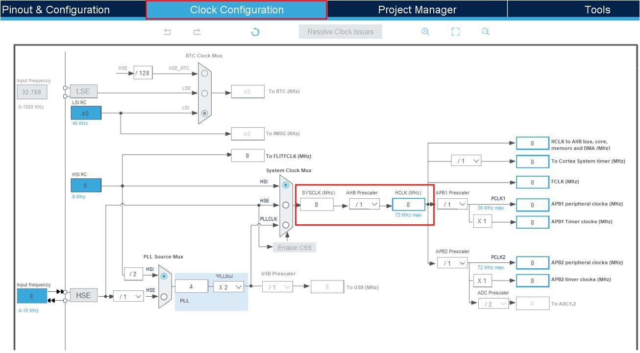
You can specify your system clock. We will set it as 72 MHz. These are the configurations we have set:

Now we will save our file. Press Ctrl + S. The following window will appear. Click ‘Yes.’ This will generate a template code for you.

Another window will appear that will ask if you want to open the perspective. Click ‘Yes.’

I2C LCD Libraries
As we are working with an I2C LCD with our STM32 Blue Pill, we will require the liquidcrystal_i2c library. This library will be used to access different functions that will enable us to display texts and numbers on the I2C display in various ways.
liquidcrystal_i2c.h
Go to Core > Inc and create a new file called ‘liquidcrystal_i2c.h‘ Copy the following code from this link and save it to this file.
You will be required to make the following modifications before saving your file.
- Change line 4 to #include “stm32f1xx_hal.h”
- Change line 58 to #define DEVICE_ADDR (0x27 << 1)
liquidcrystal_i2c.c
Similarly, head over to Core > Src and create a new file called ‘liquidcrystal_i2c.c‘ Copy the following code from this link and save it to this file.
STM32 Blue Pill I2C LCD STM32CubeIDE Code
We will use I2C LCD library functions to display text and numbers on the I2C LCD, both in a static manner and a scrolling manner.
Now let us look at our main.c file that was generated. Inside the main.c file, make sure the following code is part of your script by including the lines of code given below.
#include "main.h"
#include "liquidcrystal_i2c.h"

I2C_HandleTypeDef hi2c1;

void SystemClock_Config(void);
static void MX_GPIO_Init(void);
static void MX_I2C1_Init(void);

int main(void)
{

  HAL_Init();
  SystemClock_Config();
  MX_GPIO_Init();
  MX_I2C1_Init();

    HD44780_Init(2);
    HD44780_Clear();
    HD44780_SetCursor(0,0);
    HD44780_PrintStr("STM32 BLUE PILL");
    HD44780_SetCursor(0,1);
    HD44780_PrintStr("I2C LCD DEMO");
    HAL_Delay(2000);

    HD44780_Clear();
    HD44780_SetCursor(16,0);
    HD44780_PrintStr("SCROLL LEFT");

    for(int i=0; i<20; i++)
    {
      HD44780_ScrollDisplayLeft();
      HAL_Delay(500);
    }

    HD44780_Clear();
    HD44780_SetCursor(0,0);
    HD44780_PrintStr("SCROLL RIGHT");

    for(int i=0; i<20; i++)
    {
      HD44780_ScrollDisplayRight();
      HAL_Delay(500);
    }

    HD44780_Clear();
    HD44780_SetCursor(0,0);
    HD44780_PrintStr("Lets Count 0-10!");
    HAL_Delay(2000);

    char string[5];
    for(int counter=0;counter<= 10;counter++)
    {
      itoa(counter,string,10);
      HD44780_Clear();
      HD44780_SetCursor(0,0);
      HD44780_PrintStr(string);
      HAL_Delay(1000);
    }
    HD44780_Clear();


  while (1)
  {

  }
}
Working of the Code
We start off by including the liquidcrystal_i2c.h library to access the functions to control the I2C LCD.
#include "liquidcrystal_i2c.h"Inside the main function, first all the peripherals are initialized, system clock is configured and all the configured peripherals are initialized.
  HAL_Init();
  SystemClock_Config();
  MX_GPIO_Init();
  MX_I2C1_Init();
The first step is to initialize the I2C LCD. We use the HD44780_Init() function for initialization. This function takes in only a single parameter which is the number of rows. As we are using a 16×2 LCD, hence we have specified the ‘2’ as the parameter.
HD44780_Init(2);Next, we clear the LCD screen by calling HD44780_Clear().
HD44780_Clear();Before printing any text, we set the position of the cursor using the HD44780_SetCursor(). This function takes in two parameters. The first parameter is starting column and the second parameter is the starting row. Here we have specified the column as ‘0’ and row as ‘0’ which means the cursor is positioned at the extreme left side of the screen.
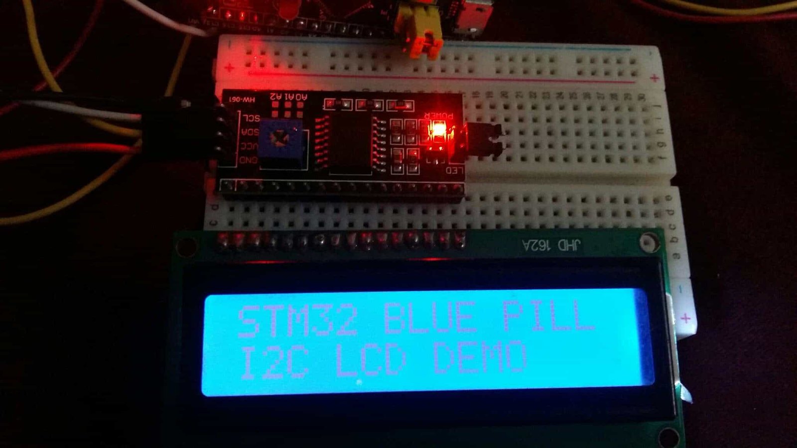
HD44780_SetCursor(0,0);After setting the cursor, we print the string “STM32 BLUE PILL” using the function HD44780_PrintStr(). This function takes in a single argument which is an array of characters that you want to print on the screen.
HD44780_PrintStr("STM32 BLUE PILL");Similarly, we set the cursor at column 0 and row 1 and print “I2C LCD DEMO.”
HD44780_SetCursor(0,1);
HD44780_PrintStr("I2C LCD DEMO");
After a delay of 2 seconds, we clear the screen and print the text “SCROLL LEFT” on the screen. The text will scroll in the left direction as we are using the function HD44780_ScrollDisplayLeft() within a for loop which runs for 20 iterations where the function is called after every 500ms.
HAL_Delay(2000);

    HD44780_Clear();
    HD44780_SetCursor(16,0);
    HD44780_PrintStr("SCROLL LEFT");

    for(int i=0; i<20; i++)
    {
      HD44780_ScrollDisplayLeft();
      HAL_Delay(500);
    }
Likewise, after a delay of 2 seconds, we clear the screen and print the text “SCROLL RIGHT” on the screen. The text will scroll in the right direction as we are using the function HD44780_ScrollDisplayRight() within a for loop which runs for 20 iterations where the function is called after every 500ms.
HD44780_Clear();
    HD44780_SetCursor(0,0);
    HD44780_PrintStr("SCROLL RIGHT");

    for(int i=0; i<20; i++)
    {
      HD44780_ScrollDisplayRight();
      HAL_Delay(500);
    }
After that, we will clear the screen and print the text “Lets Count 0-10!” on column position 0 and row position 0.
HD44780_Clear();
    HD44780_SetCursor(0,0);
    HD44780_PrintStr("Lets Count 0-10!");
    HAL_Delay(2000);
Next, we will display a counter on the LCD screen where each number gets displayed on the LCD for a second and then the screen clears.
char string[5];
    for(int counter=0;counter<= 10;counter++)
    {
      itoa(counter,string,10);
      HD44780_Clear();
      HD44780_SetCursor(0,0);
      HD44780_PrintStr(string);
      HAL_Delay(1000);
    }
    HD44780_Clear();
main.c file
This is how a complete main.c file will be after modification.
#include "main.h"
#include "liquidcrystal_i2c.h"

I2C_HandleTypeDef hi2c1;

void SystemClock_Config(void);
static void MX_GPIO_Init(void);
static void MX_I2C1_Init(void);

int main(void)
{

  HAL_Init();
  SystemClock_Config();
  MX_GPIO_Init();
  MX_I2C1_Init();

    HD44780_Init(2);
    HD44780_Clear();
    HD44780_SetCursor(0,0);
    HD44780_PrintStr("STM32 BLUE PILL");
    HD44780_SetCursor(0,1);
    HD44780_PrintStr("I2C LCD DEMO");
    HAL_Delay(2000);

    HD44780_Clear();
    HD44780_SetCursor(16,0);
    HD44780_PrintStr("SCROLL LEFT");

    for(int i=0; i<20; i++)
    {
      HD44780_ScrollDisplayLeft();
      HAL_Delay(500);
    }

    HD44780_Clear();
    HD44780_SetCursor(0,0);
    HD44780_PrintStr("SCROLL RIGHT");

    for(int i=0; i<20; i++)
    {
      HD44780_ScrollDisplayRight();
      HAL_Delay(500);
    }

    HD44780_Clear();
    HD44780_SetCursor(0,0);
    HD44780_PrintStr("Lets Count 0-10!");
    HAL_Delay(2000);

    char string[5];
    for(int counter=0;counter<= 10;counter++)
    {
      itoa(counter,string,10);
      HD44780_Clear();
      HD44780_SetCursor(0,0);
      HD44780_PrintStr(string);
      HAL_Delay(1000);
    }
    HD44780_Clear();


  while (1)
  {

  }
}
Save the main.c file after modifying it. Now we are ready to build our project.
Building the Project
To build our project press Ctrl + B or go to Project > Build All.
Your project will start building. After a few moments, your project will be successfully built if there are no errors.
Connecting ST-Link Programmer with STM32
Now as we have successfully built our project let us move ahead and upload the code to our STM32 board. First, we will have to connect our Blue Pill STM32 with an ST-Link programmer. We will be using ST-Link V2.

This will provide an interface between our computer and our STM32 board. It consists of 10 pins. We will be using pin2 SWDIO, pin6 SWCLK, pin4 GND, and pin8 3.3V to connect with our STM32 board. The SWDIO is the data input/output pin and the SWCLK is the clock pin. Follow the pin configuration given on ST-LINK V2 to identify each pin.
Follow the table below to connect both devices correctly.
| STM32 | ST-LINK V2 |
|---|---|
| VCC 3.3V pin | pin8 3.3V |
| SWDIO pin | pin2 SWDIO |
| SWCLK pin | pin6 SWCLK |
| GND pin | pin4 GND |

Additionally, move the BOOT jumper to the right to enable the microcontroller to go into programming mode.

- Now connect your ST-LINK V2 with your computer via the USB port. Both devices will power ON.
- Next press the RUN button in the IDE. The ‘Edit configuration’ window will open up. Click ‘OK’.
- After a few moments, the code will be successfully sent to the STM32 board. Otherwise, press the RESET button on your STM32 board.
- Now to bring the Blue pill back to normal mode make sure you bring the BOOT jumper back at its place.
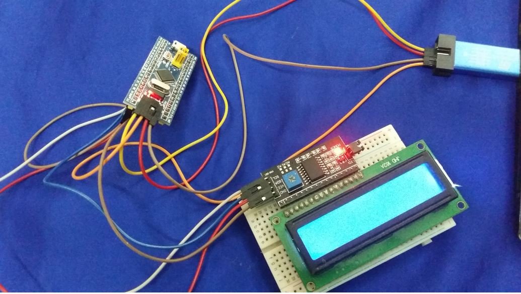
Once the code is uploaded to the board, adjust the brightness of the display through the potentiometer until the LCD starts displaying the messages.
You may also like to read:
- SSD1306 OLED with STM32 Blue Pill using STM32CubeIDE
- 4×3 Keypad with STM32 Blue Pill using STM32CubeIDE
- MicroSD Card Module with STM32 Blue Pill using STM32CubeIDE
- DHT22 Sensor with STM32 Blue Pill using STM32CubeIDE
- HC-05 Bluetooth Module with STM32 Blue Pill using STM32CubeIDE
- HC-SR04 Ultrasonic Sensor with STM32 Blue Pill using STM32CubeIDE