In this STM32 Blue Pill tutorial, we will learn about input/output GPIO pins of STM32 Blue Pill board. We will learn how to use GPIO pins of STM32 as output pins as well as input pins. Accordingly, we will also show how to interface an LED controlled via a push button with the STM32. We will be reading the value from the Push Button and controlling the LED consequently. One digital pin will be connected to the push button and another one for the LED. We will be taking digital input from the push button and the digital output will be connected with LED.
Recommended Components
The following components are used in this project or are helpful for getting started with STM32 Blue Pill development.
| Component | How it’s used in this project | Buy on Amazon |
|---|---|---|
| STM32F103C8T6 Blue Pill Board | The STM32 board reading the button and driving the LED. | Check Price |
| ST-Link V2 Programmer | SWD programmer/debugger used to flash code onto the Blue Pill. | Check Price |
| Tactile Push Button | The digital input read on PA9. | Check Price |
| 5mm LED | Driven HIGH/LOW based on the button state. | Check Price |
| Resistor Kit (220Ω & 10kΩ) | 220Ω for the LED and 10kΩ pull-down for the button. | Check Price |
| Breadboard & Jumper Wires | For wiring the button and LED to the Blue Pill. | Check Price |
As an Amazon Associate we earn from qualifying purchases. Prices and availability are accurate as of the date/time indicated and are subject to change.
A Push button will be used to control device like turning ON and OFF a light-emitting diode when the push button is pressed or not. Similarly, we can use a push button to increase or decrease the speed of dc motor. When you use the push button with STM32, we have to use GPIO pins as digital input pins. Because we will read the state of the push button. The push button will give two logical states either high or low.
You may also like to read this getting started guide:
By the end of this article you will be able to know about:
- STM32 GPIO Ports
- Configure GPIO Output Pin & Input Pin using STM32Cube IDE
- Read the Push Button State
- Write to Change the LED pin State
STM32 GPIO Ports
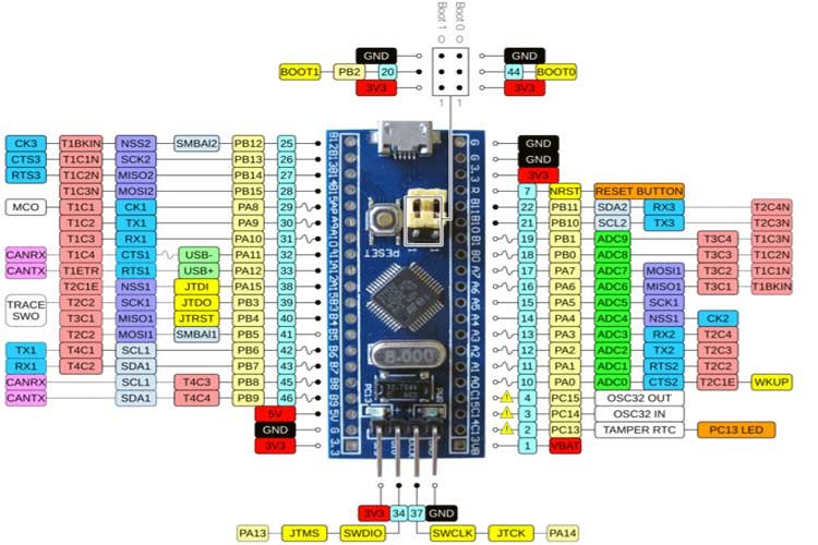
STM32F103C8 has many GPIO ports named GPIOA, GPIOB which are 16 bit wide. The STM32F103C8 features 37 I/O Pins.
Some key points of GPIO Ports:
- The STM32 GPIO ports are general input output pins which are 3.3V tolerant. Among them some can tolerate 5V. Refer to the datasheet to know about each pin.
- When the GPIO pin is configured as an input pin, the APB2 bus speed is used to set the input sampling speed for the pins. Whereas, when the pin is configured as an output, we can set the sped of the pin by programming the appropriate bits in the configuration register.
- Clock enablement is a must no matter which mode of operation is being used.
- When we set a GPIO pin as an input with Hi-Z, this makes the GPIO pin as high impedance. In other other disconnecting it.
According to the stm32f103c8 datasheet:
“Each of the GPIO pins can be configured by software as output (push-pull or open-drain), as
input (with or without pull-up or pull-down), or as peripheral alternate function. Most of the
GPIO pins are shared with digital or analog alternate functions. All GPIOs are high current capable.”
You can refer to the datasheet here
Push Button with STM32 Blue Pill Interfacing Diagram
We will read the state of the push button. The push button will give two logical states either high or low. We will connect the push button with the STM32 board using a resistor.

There are two types of resistors that can be used in this project. Pull-up and pull-down resistors. We will be using Pull- down resistors which work on the principle that whenever the push button is pressed, the input to GPIO pin will be logic high state (1) and otherwise logic low state (0). If it is a logic state high that means 1 the LED would switch on and if the logic state is low that means 0 then the LED is off. It works vice-versa if we use pull-up resistors instead.
Connection Diagram
Now we will connect the circuit with the LED and push button. The following components are required.
Required Components:
- STM32 board
- ST-LINK V2 programmer
- One push button
- One LED
- 220 ohm resistor
- 10k ohm resistor
- Breadboard
- Connecting wires
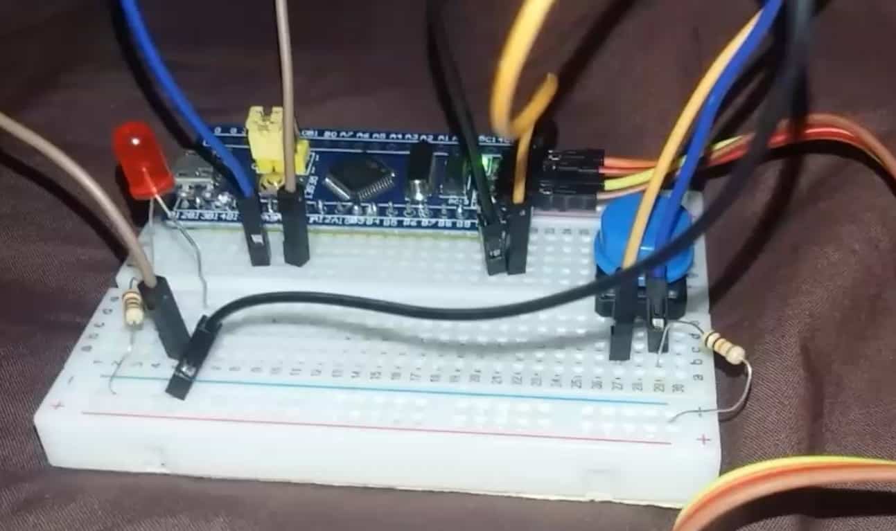
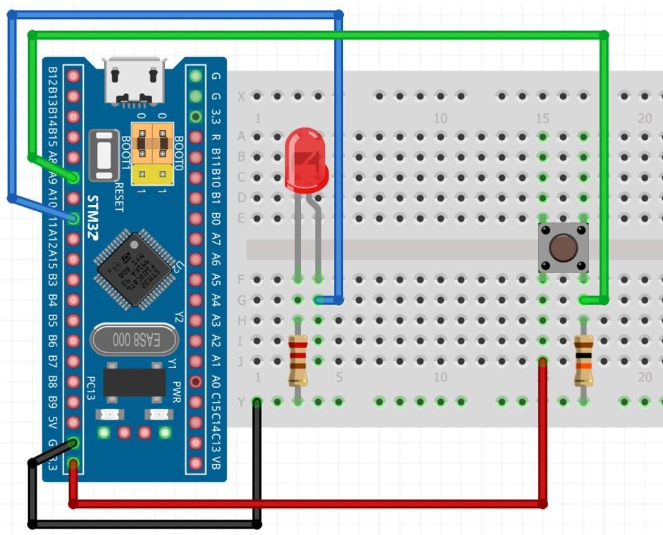
The push-button has four terminals. One terminal is powered by 3.3 volts from STM32 and the other terminal is connected by Pin A9 and the 10k ohm resistor which acts as a pull-down resistor. The other end of the resistor is connected with the common ground.
For the LED we will connect Pin A11 with the anode pin of LED, and the cathode pin is connected with the common ground through the 220-ohm resistor.
When the push button is pressed, a logic state of high (1) will be passed on A9 and the push button input will be in a high state. When the button is released a logic state of low (0) will be passed on A9 and the push button input will be in a logic state LOW. We will read the state of the push button and turn LED ON and OFF, accordingly.
Program Push Button with STM32 Blue Pill in STM32Cube IDE
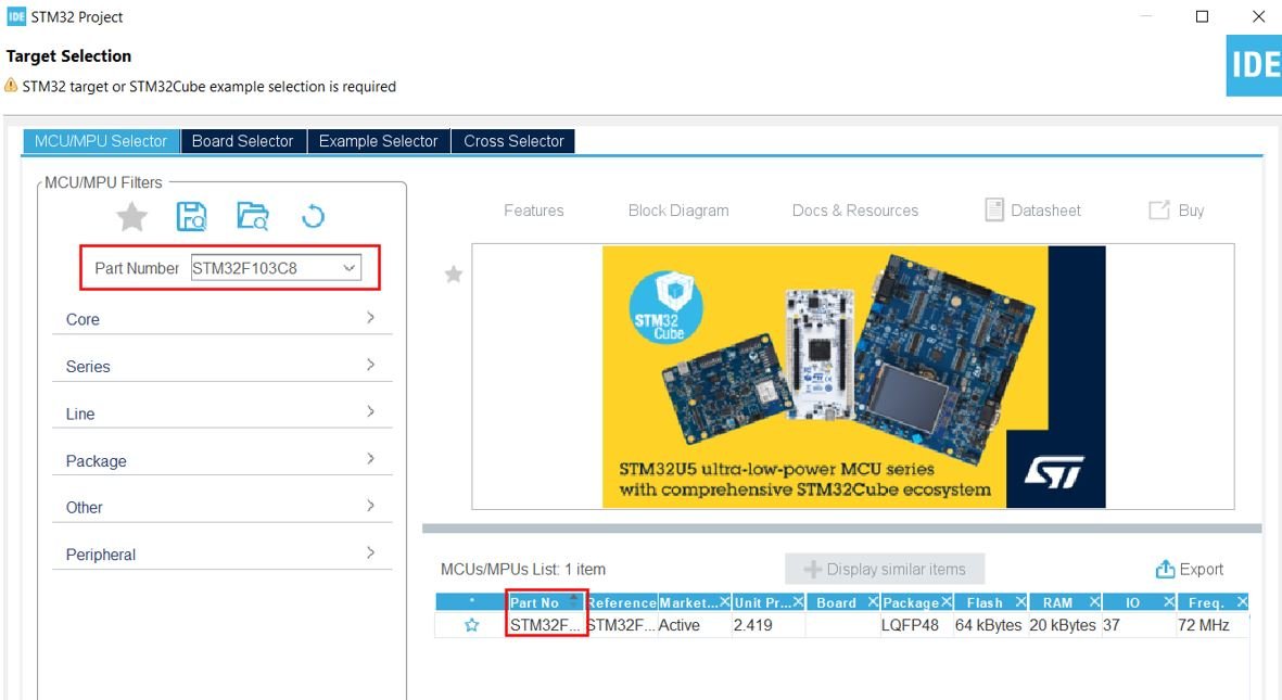
We will use STM32Cube IDE to program our STM32 board. Open the IDE and head over to a new project.
Then for the target selection, specify the STM32 Blue Pill board number. After that click at the Part No column as shown in the picture below. Then click the ‘Next’ button.
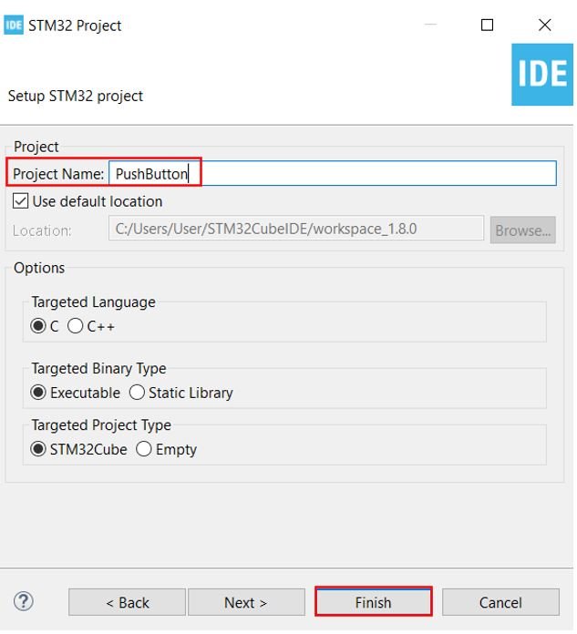
The following window will open. Here specify the name of your project then click ‘Finish’ to complete the setup of your project.
Device Configuration Tool
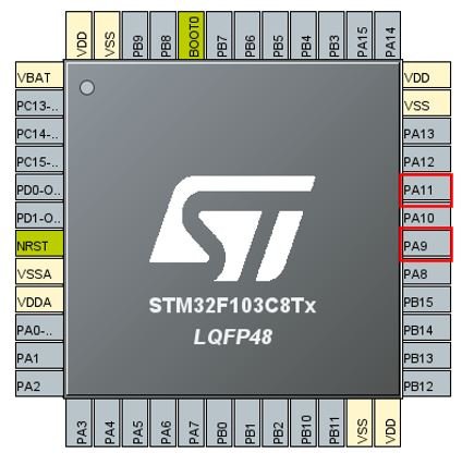
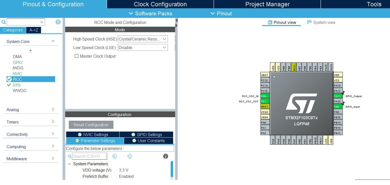
Now here comes the important part. The Device Configuration Tool will now open. Here we will configure the input and output pins. For the input pin we have chosen the digital pin PA9 and for the output pin we have chosen the digital pin PA11. PA9 in our case is connected with the push button and PA11 is connected with the LED as mentioned before.
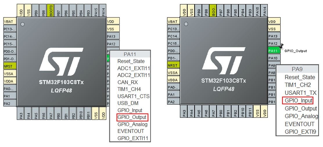
Click at PA11 and select GPIO_OUTPUT. Likewise, click at PA9 and select GPIO_INPUT.
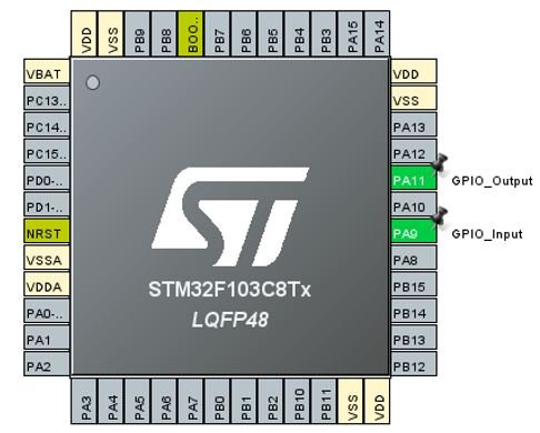
This is how the two pins will look like after attaching them with specific modes.
Now go to System Core > RCC then select ‘Crystal/Ceramic Resonator’ in from the High Speed Clock feature.
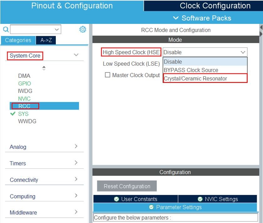
Now we have enabled the RCC external clock source.
Clock Configuration
Next go to the Clock Configuration found at the top. This will open the following window. Here we will select the clock frequency.
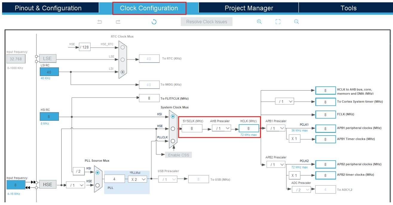
You can specify your system clock. We will set it as 72 MHz. These are the configurations we have set:

Now we will save our file. Press Ctrl + S. The following window will appear. Click ‘Yes.’ This will generate a template code for you.
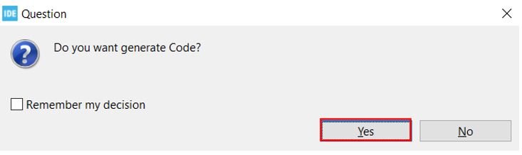
Another window will appear that will ask if you want to open the perspective. Click ‘Yes.’

Push Button with STM32 Blue Pill Code
Now the following page opens. On the right side you will be able to view the Outline of the code. This happened because we opened our code with perspective. In the centre you can view the main.c file and on the left you can view the Project Explorer. If you want to go to the Device Configuration Tool, then click the PushButton.ioc tab.
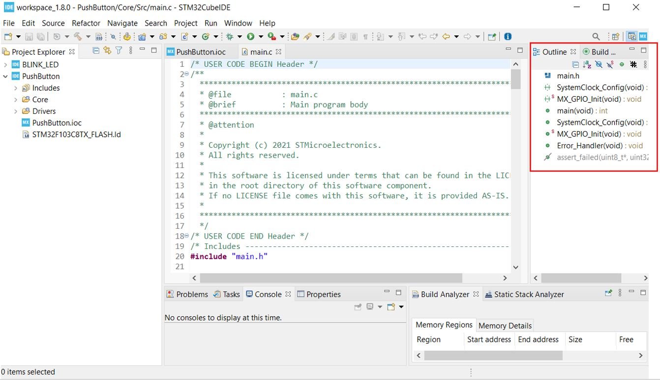
Now let us look at our main.c file that was generated. Look for the MX_GPIO_Init() function.
static void MX_GPIO_Init(void)
{
  GPIO_InitTypeDef GPIO_InitStruct = {0};

  /* GPIO Ports Clock Enable */
  __HAL_RCC_GPIOD_CLK_ENABLE();
  __HAL_RCC_GPIOA_CLK_ENABLE();

  /*Configure GPIO pin Output Level */
  HAL_GPIO_WritePin(GPIOA, GPIO_PIN_11, GPIO_PIN_RESET);

  /*Configure GPIO pin : PA9 */
  GPIO_InitStruct.Pin = GPIO_PIN_9;
  GPIO_InitStruct.Mode = GPIO_MODE_INPUT;
  GPIO_InitStruct.Pull = GPIO_NOPULL;
  HAL_GPIO_Init(GPIOA, &GPIO_InitStruct);

  /*Configure GPIO pin : PA11 */
  GPIO_InitStruct.Pin = GPIO_PIN_11;
  GPIO_InitStruct.Mode = GPIO_MODE_OUTPUT_PP;
  GPIO_InitStruct.Pull = GPIO_NOPULL;
  GPIO_InitStruct.Speed = GPIO_SPEED_FREQ_LOW;
  HAL_GPIO_Init(GPIOA, &GPIO_InitStruct);

}
This is the function that initializes the GPIO pins that we have set up in the Device Configuration Tool. Here as you can see Pin A9 is configured as an input with no pull. This means that the pin A9 is setup in high impedance. Moreover, Pin A11 is configured as an output with no pull as well. The set up speed is set to low frequency.
Then for both the pins the HAL_GPIO_Init() function is also called. This function takes in two parameters. The first parameter is the GPIO Port which is GPIOA in our case. The second parameter is &GPIO_InitStruct.
Modifying Code
Next inside the main() function go to while(1) and insert the following lines of code. These will be responsible to turn the LED ON when the push button is pressed.
while (1)
  {         //button pressed
    if(HAL_GPIO_ReadPin (GPIOA, GPIO_PIN_9))
	 {
	  //Turn LED ON
	  HAL_GPIO_WritePin(GPIOA, GPIO_PIN_11, GPIO_PIN_SET);
	  }
	 else
	 {
	  //Turn LED OFF
	  HAL_GPIO_WritePin(GPIOA, GPIO_PIN_11, GPIO_PIN_RESET);
	 }
  }
The HAL_GPIO_ReadPin() takes in two parameters: the pin connected with the push button port and the push button GPIO pin which is pin9 in our case. This function will be responsible for reading the state of the push button pin
Next the HAL_GPIO_WritePin() function takes in three parameters: the LED port, the LED pin and the state of the pin. This function will be responsible for setting the LED pin ether HIGH or LOW.
When we are specifying the third parameter as GPIO_PIN_RESET, it sets the LED pin to LOW whereas when we are specifying the third parameter as GPIO_PIN_SET, it sets the LED pin to HIGH.
The logic we are using here is that the HAL_GPIO_ReadPin() function reads the push button state. If the push button is pressed then the LED will turn ON. Otherwise, the LED will be OFF. This will be achieved through the HAL_GPIO_WritePin() functions
Save the main.c file after modifying it. Now we are ready to build our project.
main.c file
/* USER CODE BEGIN Header */
/**
  ******************************************************************************
  * @file           : main.c
  * @brief          : Main program body
  ******************************************************************************
  * @attention
  *
  * Copyright (c) 2021 STMicroelectronics.
  * All rights reserved.
  *
  * This software is licensed under terms that can be found in the LICENSE file
  * in the root directory of this software component.
  * If no LICENSE file comes with this software, it is provided AS-IS.
  *
  ******************************************************************************
  */
/* USER CODE END Header */
/* Includes ------------------------------------------------------------------*/
#include "main.h"

void SystemClock_Config(void);
static void MX_GPIO_Init(void);

int main(void)
{
  HAL_Init();
  SystemClock_Config();
  MX_GPIO_Init();
  while (1)
  {         //button pressed
     if(HAL_GPIO_ReadPin (GPIOA, GPIO_PIN_9))
    {
       //Turn LED ON
      HAL_GPIO_WritePin(GPIOA, GPIO_PIN_11, GPIO_PIN_SET);
    }
    else
    {
     //Turn LED OFF
      HAL_GPIO_WritePin(GPIOA, GPIO_PIN_11, GPIO_PIN_RESET);
    }

  }

}


void SystemClock_Config(void)
{
  RCC_OscInitTypeDef RCC_OscInitStruct = {0};
  RCC_ClkInitTypeDef RCC_ClkInitStruct = {0};

  /** Initializes the RCC Oscillators according to the specified parameters
  * in the RCC_OscInitTypeDef structure.
  */
  RCC_OscInitStruct.OscillatorType = RCC_OSCILLATORTYPE_HSE;
  RCC_OscInitStruct.HSEState = RCC_HSE_ON;
  RCC_OscInitStruct.HSEPredivValue = RCC_HSE_PREDIV_DIV1;
  RCC_OscInitStruct.HSIState = RCC_HSI_ON;
  RCC_OscInitStruct.PLL.PLLState = RCC_PLL_ON;
  RCC_OscInitStruct.PLL.PLLSource = RCC_PLLSOURCE_HSE;
  RCC_OscInitStruct.PLL.PLLMUL = RCC_PLL_MUL9;
  if (HAL_RCC_OscConfig(&RCC_OscInitStruct) != HAL_OK)
  {
    Error_Handler();
  }
  /** Initializes the CPU, AHB and APB buses clocks
  */
  RCC_ClkInitStruct.ClockType = RCC_CLOCKTYPE_HCLK|RCC_CLOCKTYPE_SYSCLK
                              |RCC_CLOCKTYPE_PCLK1|RCC_CLOCKTYPE_PCLK2;
  RCC_ClkInitStruct.SYSCLKSource = RCC_SYSCLKSOURCE_PLLCLK;
  RCC_ClkInitStruct.AHBCLKDivider = RCC_SYSCLK_DIV1;
  RCC_ClkInitStruct.APB1CLKDivider = RCC_HCLK_DIV2;
  RCC_ClkInitStruct.APB2CLKDivider = RCC_HCLK_DIV1;

  if (HAL_RCC_ClockConfig(&RCC_ClkInitStruct, FLASH_LATENCY_2) != HAL_OK)
  {
    Error_Handler();
  }
}


static void MX_GPIO_Init(void)
{
  GPIO_InitTypeDef GPIO_InitStruct = {0};

  /* GPIO Ports Clock Enable */
  __HAL_RCC_GPIOD_CLK_ENABLE();
  __HAL_RCC_GPIOA_CLK_ENABLE();

  /*Configure GPIO pin Output Level */
  HAL_GPIO_WritePin(GPIOA, GPIO_PIN_11, GPIO_PIN_RESET);

  /*Configure GPIO pin : PA9 */
  GPIO_InitStruct.Pin = GPIO_PIN_9;
  GPIO_InitStruct.Mode = GPIO_MODE_INPUT;
  GPIO_InitStruct.Pull = GPIO_NOPULL;
  HAL_GPIO_Init(GPIOA, &GPIO_InitStruct);

  /*Configure GPIO pin : PA11 */
  GPIO_InitStruct.Pin = GPIO_PIN_11;
  GPIO_InitStruct.Mode = GPIO_MODE_OUTPUT_PP;
  GPIO_InitStruct.Pull = GPIO_NOPULL;
  GPIO_InitStruct.Speed = GPIO_SPEED_FREQ_LOW;
  HAL_GPIO_Init(GPIOA, &GPIO_InitStruct);

}


void Error_Handler(void)
{
  /* USER CODE BEGIN Error_Handler_Debug */
  /* User can add his own implementation to report the HAL error return state */
  __disable_irq();
  while (1)
  {
  }
  /* USER CODE END Error_Handler_Debug */
}

#ifdef  USE_FULL_ASSERT
/**
  * @brief  Reports the name of the source file and the source line number
  *         where the assert_param error has occurred.
  * @param  file: pointer to the source file name
  * @param  line: assert_param error line source number
  * @retval None
  */
void assert_failed(uint8_t *file, uint32_t line)
{
  /* USER CODE BEGIN 6 */
  /* User can add his own implementation to report the file name and line number,
     ex: printf("Wrong parameters value: file %s on line %d\r\n", file, line) */
  /* USER CODE END 6 */
}
#endif /* USE_FULL_ASSERT */
Building the Project
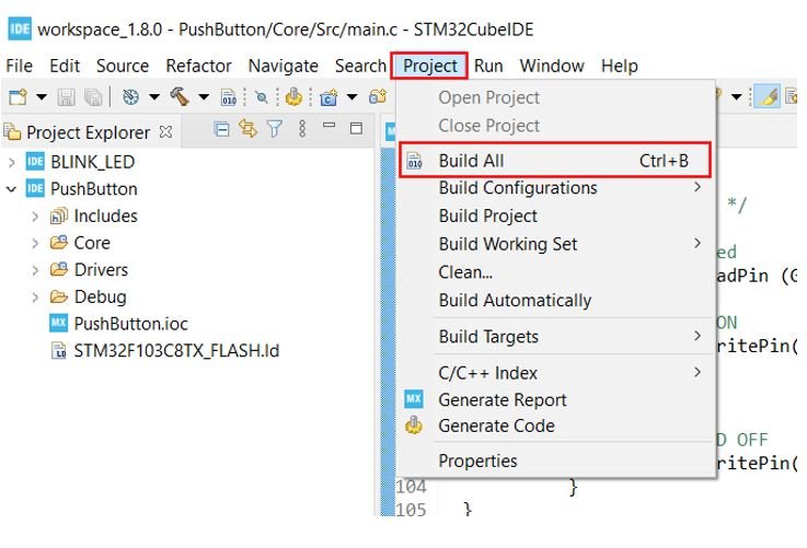
To build our PushButton project press Ctrl + B or go to Project > Build All.
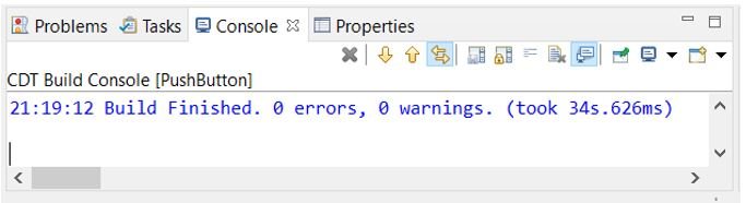
Your project will start building. After a few moments, your project will be successfully built if there are no errors.
Connecting ST-Link Programmer with STM32
Now as we have successfully built our PushButton project let us move ahead and upload the code to our STM32 board. To do that, first we will have to connect our Blue Pill STM32 with a ST-Link programmer. We will be using ST-Link V2.

This will provide an interface between our computer and our STM32 board. It consists of 10 pins. We will be using pin2 SWDIO, pin6 SWCLK, pin4 GND and pin8 3.3V to connect with our STM32 board. The SWDIO is the data input/output pin and the SWCLK is the clock pin. Follow the pin configuration given on the ST-LINK V2 to identify each pin.
Follow the table below to connect both the devices correctly.
| STM32 | ST-LINK V2 |
| VCC 3.3V pin | pin8 3.3V |
| SWDIO pin | pin2 SWDIO |
| SWCLK pin | pin6 SWCLK |
| GND pin | pin4 GND |

Additionally move the BOOT jumper to the right to enable the microcontroller to go into programming mode.

Now connect your ST-LINK V2 with your computer via the USB port. Both the devices will power ON.
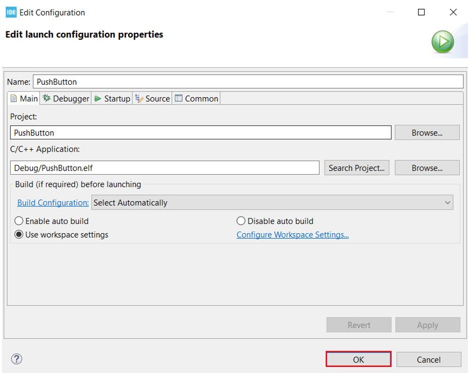
Next press the RUN button in the IDE. The following ‘Edit configuration’ window will open up. Click ‘OK’.
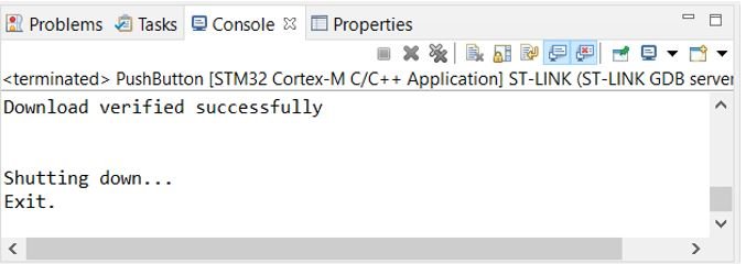
After a few moments, the code will be successfully sent to the STM32 board. You can view the message in the Console terminal.
Otherwise, press the RESET button on your STM32 board.
Now to bring the Blue pill back to normal mode make sure you bring the BOOT jumper back at its place. After doing that press the RESET button on the board.
Now press the push button and the LED will turn ON. When you will release the button the LED turns OFF.
Watch the demonstration video below to have a better insight.