This is a getting started tutorial on STM32 Blue Pill using STM32Cube IDE. In this tutorial, we will learn to control GPIO pins of STM32 Blue Pill. As an example, we will see how to configure them as digital output pins using HAL GPIO driver and STM32Cube IDE.
Recommended Components
The following components are used in this project or are helpful for getting started with STM32 Blue Pill development.
| Component | How it’s used in this project | Buy on Amazon |
|---|---|---|
| STM32F103C8T6 Blue Pill Board | The board whose onboard LED (PC13) we blink via GPIO. | Check Price |
| ST-Link V2 Programmer | SWD programmer/debugger used to flash code onto the Blue Pill. | Check Price |
| Breadboard & Jumper Wires | Handy for wiring the programmer and any external parts. | Check Price |
As an Amazon Associate we earn from qualifying purchases. Prices and availability are accurate as of the date/time indicated and are subject to change.
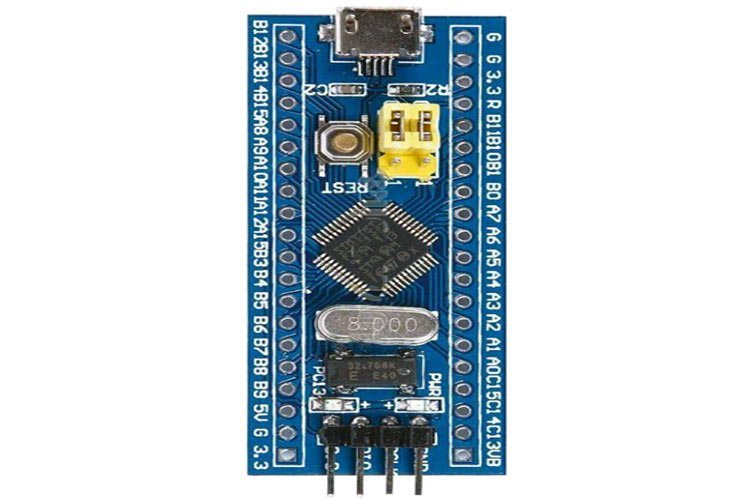
STM32 Blue Pill Introduction
This low-cost STM32 series development board comes with an STM32F103C8T6 microcontroller. STM32F103C8T6 is one of the mid-range microcontroller units of the STM32F103x8 family based on RISC architecture. An integrated Blue Pill Development Board was introduced as a low-cost board as an alternative to STMicroelectronics STM discovery boards. The price of Blue Pill is around 2-3$.
STM32F103C8T6 microcontroller comes with GPIO pins, processor, memory, USB port, Analog to Digital Converters, and other peripherals. An ARM Cortex Core with an amazing speed of 72 MHz and remarkable power efficiency.
This tutorial focuses on Blue pill STM32F103C8 microcontroller featured by ARM Cortex-M and how to program it using STM32Cube. STM32Cube is an IDE provided by STM32 itself.
STM32F103C8T6 Introduction
STM32F103C8T6 Blue Pill Development Board contains a 32-bit Cortex-M3 RISC ARM core with an internal oscillator of 4 -16 MHz. It is a CMOS flash technology chip. This chip has 37 GPIO pins and 10 Analog pins. It has some modern communication interfaces like a CAN and a USB port. The peripherals give outstanding control of the board as it operates at very low voltage, so it is suitable for low-power applications. It also comes with an integrated watchdog and a window watchdog timer for the proper execution of instructions.
Pinout
Following diagram shows the pinout of the STM32F103C8T6 Blue Pill Development Board:
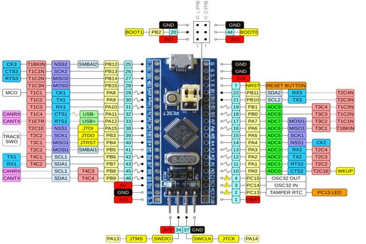
For further information regarding STM32 Blue pill, please read through our previous article: STM32F103C8T6 Blue Pill Development Board
STM32 Blue Pill GPIO Pins
It has a total of 37 GPIO pins which are shared between four ports – PORTA and PORTB (16 pins), PORTC (3 pins), and PORTD (2 pins). Each pin can sink/source current of about 6mA. Furthermore, each pin has an internal Pull-up and pull-down resistors which can be enabled through programming.
Note: All these GPIO pins have multiple functions and are shared across different peripherals such as UART, I2C, SPI, and PWM pins, etc.
Downloading & Installing STM32Cube IDE
We will use STM32Cube development platform to program our STM32 board. To do that we will first show you how to set up the IDE in your system.
The first step is to download the program.
Go to the following link:( https://www.st.com/en/development-tools/stm32cubeide.html#get-software) and click ‘Get latest’ block according to your operating system. We are using Windows.

The following form will open up. You will have to register your account. Give the following information and click the ‘Download’ button. If you already have an account on my.st.com then you can use that to login as well.
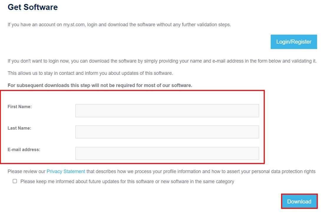
After specifying your personal information and clicking the download button your registration will be complete. You will be given a link in your email address to validate your email address after which the download will automatically start. Note that this email address is the one which you used for registration. The email will be sent by STMicroelectronics.
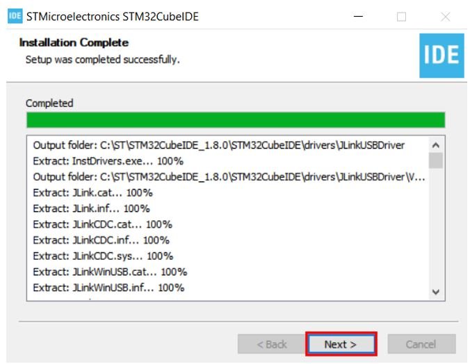
A few moments later, after specifying the directory your download will start. After opening the .zip file you will be asked for your agreement. After accepting the agreement and choosing the desired location to install the IDE, the installation process will start. It will take some time for STM32Cube to get installed.
After the installation is complete, click ‘Next’.
After the installation is completed, click ‘Finish’ to close the setup. Your desktop will now have a shortcut to STM32Cube created.

STM32 Blue Pill LED Blinking Example
As mentioned earlier, we will learn to use GPIO pins of STM32 Blue Pill as digital output pins. For demonstration purposes, we will create a LED blinking example. This board has an onboard LED connected to GPIO pin 13.
First, lets see how to write your first program for STM32 Blue Pill in STM32Cube IDE.
Write your first STM32 Blue Pill Program in STM32Cube IDE
Now as we have already installed the STM32Cube application in our system, let us learn how to use it to program our STM32 boards.
Open the application. You will be asked to specify the directory for the workplace. You can specify the directory and also tick the box below to keep this as the default directory. Next, click ‘Launch’ to start the application.

The STM32Cube workspace will open.
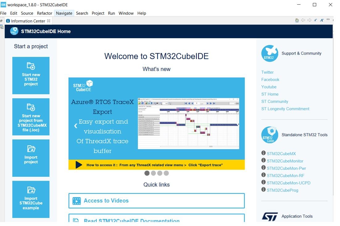
Creating Project for STM32 in STM32Cube
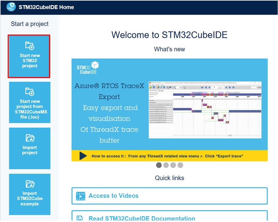
Now click ‘Start new STM32 project’.
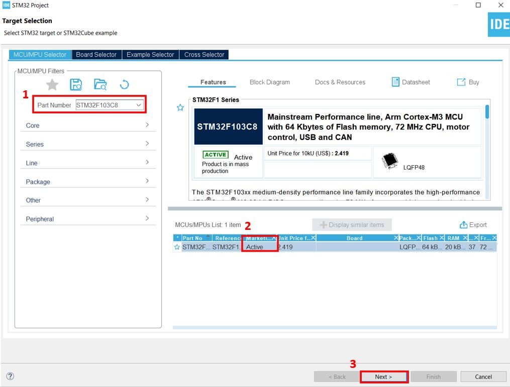
The Target Selection will open.

Select your device from the ‘Part Number.’ We are working with ‘STM32F103C8’.Then click any column entry and then click the ‘Next’ button to proceed further.
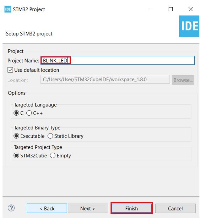
Give your project a name. As we are going to blink the on-board LED of our STM32 board hence we have named our project as ‘BLINK_LED.’ Then click ‘Finish.’
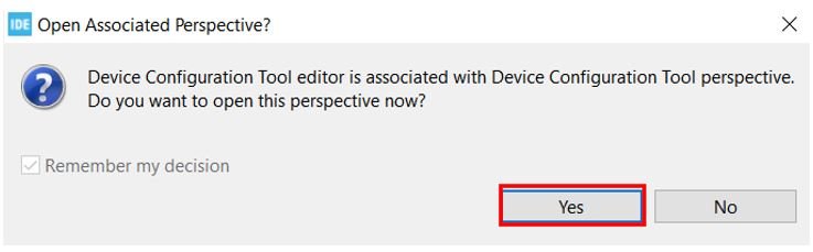
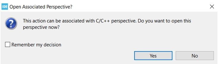
You will be asked to open associated perspective. Click ‘Yes’.
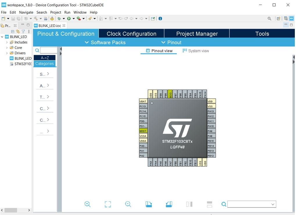
Device Configuration Tool
Now the Device Configuration Tool window will open up. We will be able to set pin specific functions here.
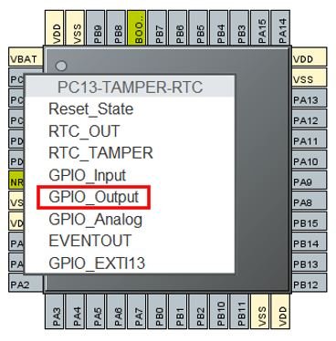
STM32 has an on-board LED connected at PC-13. Refer to the detailed pin out of the board above. Click on PC-13 pin on the Device configuration Tool.

A list of functions will appear associated with the pin. We will set this pin as a ‘GPIO Output.’
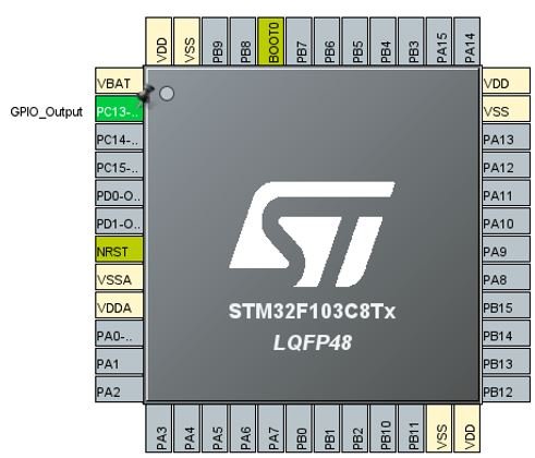
This is how it will look. Here you can see that we have attached GPIO_Output to PC-13.
Additionally, we have more options for pins as well. Go to System Core > GPIO > PC-13 and the pin configuration for PC-13 will open up. Here we have given the pin a user label of ‘LED.’ You can see in Device Configuration Tool, that now PC-13 has been given the label ‘LED.’
Apart from the label, there are several other options to choose from including GPIO output level, mode, pull-up/pull-down state etc.

Now we will save our file. Press Ctrl + S. The following window will appear. Click ‘Yes.’ This will generate a template code for you.

Another window will appear that will ask if you want to open the perspective. Click ‘Yes.’
Code
Now the following page opens. On the right side, you will be able to view the Outline of the code. This happened because we opened our code with perspective.
In the center, you can view the main.c file and on the left you can view the Project Explorer.
If you want to go to the Device Configuration Tool, then click the BLINK_LED.ioc tab.

STM32 Blue Pill LED Blinking Code
Now let us modify the main.c file for our BLINK_LED project. Our aim is to blink the on-board LED indefinitely after a delay.
First, inside the main() function go to while(1) and insert the following lines of code. These will be responsible to blink the onboard LED infinitely.
  while (1)
  {
    HAL_GPIO_WritePin(LED_GPIO_Port, LED_Pin, GPIO_PIN_RESET);
    delay(500000);
    HAL_GPIO_WritePin(LED_GPIO_Port, LED_Pin, GPIO_PIN_SET);
    delay(500000);
  }
Now what is happening is that the HAL_GPIO_WritePin() function takes in three parameters: the onboard LED port, the onboard LED pin, and the state of the pin. This function will be responsible for setting the onboard LED pin either HIGH or LOW.
Notice that we had labelled the onboard LED as ‘LED’ hence we have specified LABEL_GPIO_Port and LABEL_Pin : the first two parameters as LED_GPIO_Port and LED_Port. Remember to replace ‘LABEL’ with your own pin label.
The case where we are specifying the third parameter as GPIO_PIN_RESET, it sets the onboard LED pin to LOW whereas when we are specifying the third parameter as GPIO_PIN_SET, it sets the onboard LED pin to HIGH.
In between these two functions, we are calling the delay() function. It is not an in-built function therefore we will have to define it as well. Insert the following definition of the delay() function after Error_Handler().
void delay (int x)
{
  volatile int i,j;
  for (i=0 ; i < x ; i++)
  {
     j++;
  }
  return;
}
Additionally, add the prototype of the delay() function with the rest of the private function prototypes as shown below:
/* Private function prototypes -----------------------------------------------*/
void SystemClock_Config(void);
static void MX_GPIO_Init(void);
void delay (int x);
Save the main.c file after modifying it. Now we are ready to build our project.
Building the Project
To build our BLINK_LED project press Ctrl + B or go to Project > Build All.

Your project will start building. After a few moments, your project will be built if there are no errors.

Connecting ST-Link Programmer with STM32
Now as we have successfully built our BLINK_LED project let us move ahead and upload the code to our STM32 board. To do that, first we will have to connect our Blue Pill STM32 with a ST-Link programmer. We will be using ST-Link V2.

This will provide an interface between our computer and our STM32 board. It consists of 10 pins. We will be using pin2 SWDIO, pin6 SWCLK, pin4 GND, and pin8 3.3V to connect with our STM32 board. The SWDIO is the data input/output pin and the SWCLK is the clock pin. Follow the pin configuration given on the ST-LINK V2 to identify each pin.
Follow the table below to connect both devices correctly.
| STM32 Blue Pill | ST-LINK V2 |
|---|---|
| VCC 3.3V pin | pin8 3.3V |
| SWDIO pin | pin2 SWDIO |
| SWCLK pin | pin6 SWCLK |
| GND pin | pin4 GND |

Additionally move the BOOT jumper to the right to enable the microcontroller to go into programming mode.

Now connect your ST-LINK V2 with your computer via the USB port. Both the devices will power ON.

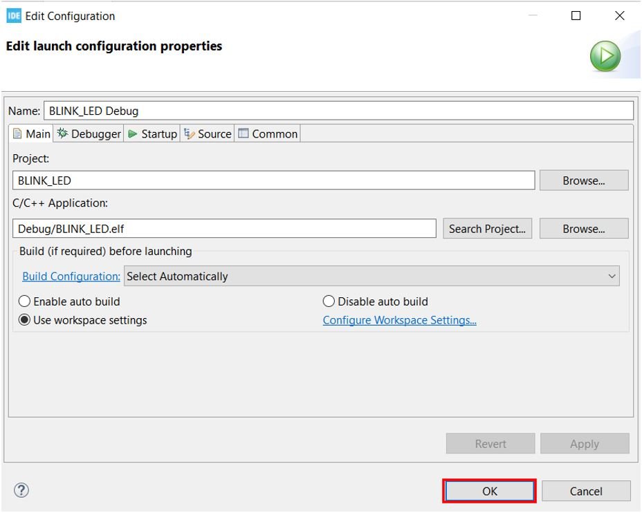
Next press the RUN button in the IDE. The following ‘Edit configuration’ window will open up. Click ‘OK’.
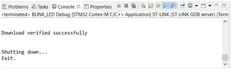
After a few moments, the code will be successfully sent to the STM32 board. You can view it in the Console terminal.
Otherwise, press the RESET button on your STM32 board.
Now to bring the Blue pill back to normal mode make sure you bring the BOOT jumper back at its place. After doing that press the RESET button on the board. Immediately, the onboard LED will start blinking.
Hello, I am delighted to see posts about STM32F103, please continue publishing more content for STM32, and preferably publsih tutorials that explain low level coding using registers not just the HAL.
We have a plan to do register level tutorials in the future also. We currently have TM4C123 Tiva Launchpad tutorials with register level programming:
https://microcontrollerslab.com/category/tiva-launchpad/
I’m a long-time follower of your Arduino and ESP32 articles and have built projects from them. I’m a bit unclear why you have chosen to introduce us to the STM32 cube. Is it a pricing factor or are you leading us to some higher-level projects because of the 72 MHz speed?
Thanks for the fun, just don’t want to spread myself too wide and lose focus.
Hi Paul,
Good to hear from you. Actually, I got a lot of emails regards STM32Cube IDE tutorials and I decided to select STM32 Blue Pill for this series. Because Blue Pill is a low-cost board. We also have a plan to make an STM32 Nucleo tutorial with Arduino Framework. Keep visiting us.
Thanks for the update. Look forward to the new series.
I’m a long time following your posts ESP32. I found this post useful for stm32 to start.
I’d like to power up my code to design for tiny machine learning and computer vision projects.
Thanks for your guides and posts.
can you give me a .hex file for this code ?