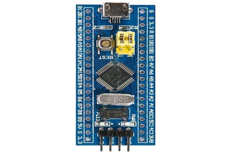
STM32F103C8T6 is one of the mid-range microcontroller units of the STM32F103x8 family based on RISC architecture. An integrated Blue Pill Development Board was introduced as a low-cost board as an alternative to STMicroelectronics STM discovery boards. The price of Blue Pill is around 2-3$.
STM32F103C8T6 microcontroller comes with GPIO pins, processor, memory, USB port, Analog to Digital Converters, and other peripherals. An ARM Cortex Core with an amazing speed of 72 MHz and remarkable power efficiency.
This tutorial is an introduction to the STM32F103C8T6 Blue Pill Development Board. All the features, specifications, pin configuration, GPIO pins and peripherals, and applications will be discussed here.
STM32F103C8T6 Introduction
STM32F103C8T6 Blue Pill Development Board contains a 32-bit Cortex-M3 RISC ARM core with an internal oscillator of 4 -16 MHz. It is a CMOS flash technology chip. This chip has 37 GPIO pins and 10 Analog pins. It has some modern communication interfaces like a CAN and a USB port. The peripherals give outstanding control of the board as it operates at very low voltage, so it is suitable for low-power applications. It also comes with an integrated watchdog and a window watchdog timer for the proper execution of instructions.
STM32F103C8T6 Blue Pill Pinout
Following diagram shows the pinout of the STM32F103C8T6 Blue Pill Development Board:
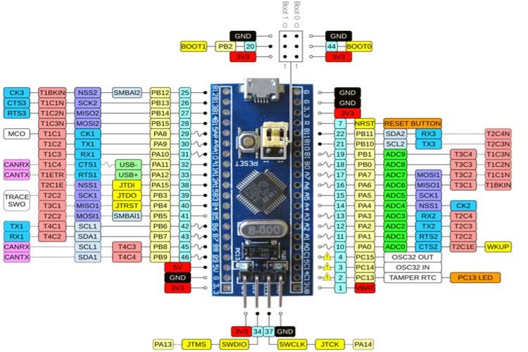
STM32F103C8T6 Blue Pill Pin Configuration
Let us discuss the pinout of the STM32F103C8T6 Blue Pill Development Board. The pin configuration detail in tabular is mentioned below:
| Type | Pin Name | Function |
|---|---|---|
| Power | – 3.3 Volts – 5 Volts – GND | 1. Operational Output Voltage 2. Power Supply from USB or 5V external source pin 3. Ground Pin |
| Analog Pins | PA0-PA7, PB0-PB1 | 10, 12-bit resolution ADC pins |
| I/O Pins | PA0-PA15, PB0-PB15, PC13-PC15 | 37 General Purpose I/O pins |
| External Interrupts | PA0-PA15, PB0-PB15, PC13-PC15 | Interrupt pins |
| PWM | PA0-PA3, PA6-PA10, PB0-PB1, PB6-PB9 | 15 Pulse-width Modulation pins |
| Serial Communication ( UART) | TX1, RX1, TX2, RX2, TX3, RX3 | RTS, CTS USART pins |
| SPI | MISO0, MOSI0, SCK0, MISO1, MOSI1, SCK1, CS0 | 2 Serial Peripheral Interface pins |
| CAN | CAN0TX, CAN0RX | Controller Area Network Bus pins |
| I2C | SCL1, SCL2, SDA1, SD2 | Inter-Integrated Circuit Serial Data and Clock pins |
| Built-in LED | PC13 | LED for Indication |
- External Interrupts: The hardware interrupts are operated to detect external signals.
- PWM: A total of 15 pulse width modulations pins to generate analog voltage signals from digital PWM outputs.
- RTS/CTS: Request-to-Send/Clear-to-Send is a protocol that tells about the transmission and reception of data to keep the flow of data and signals in check.
- SPI: Serial Peripheral Interface to communicate between the Microcontroller Unit and peripherals.
- CAN: A multi-serial bus also responsible for dual directional communication.
- I2C: Another serial interface protocol for synchronized bit-wise data transmission.
Features and Specifications
| Features and Peripherals | Availability |
|---|---|
| Architecture | RISC |
| Pin Count | 47 |
| SRAM | 20 kiloBytes |
| Serial wire Debug | 1 |
| Flash Memory | 64/128 KiloBytes |
| CPU speed | 72 MHz (max) |
| USB Connector | Micro |
| ADC | 2 |
| Number of Timers | 7 |
| Communication Interfaces | 9 |
| USB module | Yes |
| I2C | 2 |
| SPI | 2 |
| Operational Temperature | -400C – 1050C |
| Source/Sink Current | 6 mA |
| Operational Voltage | 2.0V – 3.6V |
| USART module | 3 |
| Internal Oscillator | 4-16 MHz |
| Window watchdog timer (WWDT) | Yes |
| JTAG debug Interface | 1 |
Some of the detailed features include :
- A Cyclic Redundancy Check (CRC) for monitoring the data corruption
- Three different boot options(through user flash or system memory or SRAM) to reorganize the Flash Memory through USART1
- 7 different timers for different sampling rates for analog signals
- A JTAG(Joint Test Action Group) serial protocol for debugging and testing the microcontroller unit
- A Phase-Locked Loop(PLL) clock for stability by phasing output and input signals
- A Window watchdog timer for observing the errors in signal reception and transmission
STM32F103C8T6 Blue Pill Schematic Diagram
Following picture shows the schematic diagram for your reference. In case your Blue Pill got damaged, you can refer to this schematic diagram to replace faulty components:

How to Program STM32F103C8T6 Development Board
There are two ways to program an STM32F103C8T6 Development Board. By using the following methods :
- STLink USBDongle
- External USB or Serial Converter
Support Compilers
There are many options for compilers and IDEs are available to write programs and flash code to STM32F10C8T6 Blue Pill. But these are two the are the most popular and easy to use compilers.
Keil uvision
Softwares like Kiel/CubeMX and STLink’s software are also used to compile and upload programs. This is done through a single wire debug interface which is designed for ARM Cores for the transmissions and Memory access. You can refer to these getting started tutorials on Keil vision:
- How to download and install Keil uVision for ARM
- Getting started with Keil uVision: Write your first Program
Arduino IDE
This MCU is compatible with Arduino Software. It can be programmed using Arduino Compilers. Arduino uses two compilers i.e. avr-g++ and arm-none-eabi-g++. The code can be burnt on the MCU using UART1 pins through the external USB.
To program the STM32F10C8T6 through Arduino Software, one must select the required board from the menu of boards provided by the software. Then download suitable files for the board to program efficiently. Sample sketches of Arduino, for example, Blink can be uploaded to the MCU as the development has an integrated LED. Check these Arduino IDE getting started tutorials:
Applications
- Robotics
- Medical systems
- Home automation systems
- Low-cost embedded systems
- Consumers equipment
- GPS systems
- Industrial Applications
2D Diagram
STM32F103C8T6 comes in two packages, i.e. LQFP48, UFQFPN48. The following figure shows the 2d model of UFQFPN48. It shows us the physical dimensions of the components required when a PCB card is designed.

Related Development Boards:
hi, do you let me to have sch file blue pill? thanks ?