UART Communication stands for Universal asynchronous receiver-transmitter. It is a dedicated hardware device that performs asynchronous serial communication. It provides features for the configuration of data format and transmission speeds at different baud rates. A driver circuit handles electric signaling levels between two circuits. A Universal asynchronous receiver-transmitter (UART) Communication is usually an individual component or part of an integrated circuit. We can use it for communications over a computer or its peripheral devices such as a mouse, monitor or printer. In microcontroller chips, there are usually a number of dedicated UART hardware peripherals available.
UART communication Introduction
Universal Asynchronous Receive Transmit (UART) or Serial communication is one of the most simple communication protocols between two devices. It transfers data between devices by connecting two wires between the devices, one is the transmission line while the other is the receiving line. The data transfers bit by bit digitally in form of bits from one device to another. The main advantage of this communication protocol is that its not necessary for both the devices to have the same operating frequency. For example, two microcontrollers operating at different clock frequencies can communicate with each other easily via serial communication. However, a predefined bit rate that is referred to as baud rate usually set in the flash memory of both microcontrollers for the instruction to be understood by both the devices.
Transmitting and receiving serial data
The transmitting UART takes bytes of data and transmits the bits in a sequential form. The second transmitter which is the receiver reassembles the bits into a complete byte. Serial transmission of data through a single wire is actually more cost-effective than parallel transmission through multiple wires.
Communication between two UART devices may be simplex, full-duplex or half-duplex. Simplex communication is a one-direction type of communication where the signal moves from one UART to another. It doesn’t have provision for the receiving UART to send back signals. A full-duplex is when both devices can transmit and receive communications at the same time. A half-duplex is when devices take turns to transmit and receive.
Structure of a UART Protocol
- A UART contains a clock generator. This allows the sampling in a bit period.
- It also contains input and output shift registers.
- Transmitting and receiving control.
- A read or write control logic.
- Other optional components of a UART are: transmit or receive buffers, FIFO buffer memory, and a DMA controller.
UART technology
There was a time not so long ago when keyboards, mice, and printers had thick cables and clunky connectors. These had to be literally screwed into the computer. These devices where using UART to communicate with computers. Although these clunky cables have been replaced with USB, you can still find UARTs being used in DIY electronics such as Raspberry Pi, Arduino, and other common microcontrollers. We can use it to connect Bluetooth modules and GPS modules.
UART has a different transfer protocol than other communication protocols such as SPI and I2C. It is a physical circuit fount in a microcontroller. It can also function as a stand-alone integrated circuit. One significant advantage of UART is that it only relies on two wires to transmit data.
How two Device Communicate through UART
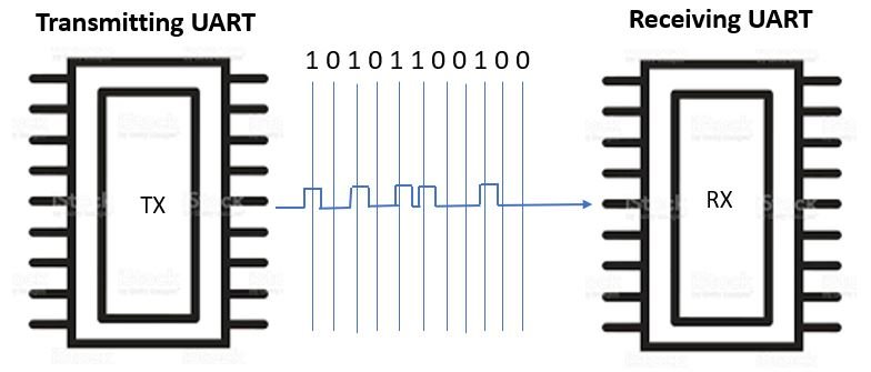
It takes two UART’s to communicate directly with each other. On one end the transmitting UART converts parallel data from a CPU into serial form then transmits the data in serial form to the second UART which will receive the serial data and convert it back into parallel data. This data can then be accessed from the receiving device.
Instead of cloak signals the transmitting and receiving bit use start and stop bit signals for the data packages. These start and stop bits define the beginning and the end of the data packages. Therefore the receiving UART knows when to start and stop reading the bits.
The Receiving UART will detect the start bit then start reading the bits. The specific frequency used to read the incoming bits is known as the baud rate. The baud rate is a measure used for the speed of data transfer. The unit used for baud rate is bits per second (bps). In order for the data transfer to be a success both the transmitting and receiving UART must operate at almost the same baud rate. However, if the baud rates differ between both UARTs they must only differ by 10%. The receiving and transmitting UART must be configured to receive the same data packages.
How UART communication works

Now let us discuss the transmission of data through UART in a step by step manner.
- Firstly, the data bus sends the data to the transmitting UART. The transmitting UART receives data from a data bus. A data bus is used to send data from another device such as a microcontroller, memory or CPU.

- When the transmitting UART receives the data it processes the data by adding a start bit and a stop bit. This, in turn, creates a data package.

- The next step is the transmission of the data from the transmitting UART to the receiving UART. The whole data packet including the data packet, start and stop bits is sent to the receiving UART serially. The data line is sampled at the pre-configured baud rate by the receiving UART.
Bit by bit the data packet is serially output at the Tx pin. UART will then read the data packet bit by bit through its Rx pin
- At the receiving side, the receiving UART gets rid of the start bit, parity bit, and stop bit from the data frame. This is to convert the data back to its original form.
- Receiver will finally transfer the data packet in parallel to the data bus
Explanation of Timing Diagram
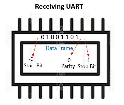
This is how UART transmitted data is organized: It is organized into packets that have one start bit, 5 to 9 data bits. A parity bit is optional, and 2 stop bits.
- Start Bit: When not transmitting data the UART data transmission line is usually high voltage. In order to start the transfer process the transmitting UART switches from high voltage to low voltage for one clock cycle. The receiving UART will detect the high to low voltage transition and start reading the bits at the accurate baud rate.
- Parity: Parity is the oddness or evenness of a number. The parity bit functions to tell the receiving UART if the data has changed during transmission. Bits can change due to electromagnetism, different baud rates or long-distance transmission of data. The UART reads the data frame after receiving the data. It then counts the number of bits and checks if they are even or odd. If the parity bit is a 0 then it is even parity. If the bit is a 1 then it is an odd parity. For the UART to know that the transmission is free of errors the parity bit has to match the data.
- Stop bits: For at least two-bit duration the transmitting UART drives the transmission line from a low to a high voltage.
Baud Rate
The communication between two devices via UART Protocol occurs by transmission of bits. A total of 8 bits are sent one right after the other to transmit a byte. A bit is either a logical low or high. The time interval between two bits is called the baud rate or bit rate. it must be defined in both devices so the sending device can encode the data into bits with this specific time interval and the receiver expects the successive bits at the right time. The most commonly used baud rates is 9600 bits per second. Although other baud rates are also used, but the higher the bit rate, the more chances there are of data corruption. Lower bit rates are used when there is greater physical distance between two devices because the length of the wire increases resistance and thus deteriorates the signal.
Timing Diagram of UART

The data in Serial communication is sent by transmitting data packets. Each data packet consists of starting bit, data byte (8 bits), a parity bit (sometimes optional) and a stop bit.
- Start bit is sent before sending the data byte to inform the receiver device to start logging the data. This bit is active low, meaning that the bit goes low when it has to notify the receiver.
- After the starting bit, data byte is sent. 8 consecutive bits are transmitted and their time is dependent on the baud rate.
Timing diagram Working
- After the data byte, parity bit is sent. This bit is optional and is used to check for data corruption during transmission. When the data byte is being transmitted, number of high bits are counted from the total 8 bits of the data byte. Now two types of parity checks can be implemented, Odd or Even.
- If, for example the number of high bits were 3 in the data byte which is an odd number, the parity bit in case of odd parity will be set to 1 and it will be set to zero in case of even parity check. This parity bit is encoded by the transmitter device into the data packet.
- Now when the receiver receives the data packet, it also counts the number of high bits in the data byte and compares it with the parity bit. If the parity bit confirms the data, it is further processed and if the parity bit and number of high bits in the data byte don’t match, the data is discarded as it is corrupt and error counter is incremented. If this error counter exceeds a certain value, it is advised to reduce the baud rate which will increase the data quality at cost of reduced speed.
- After Parity bit, stop bit is issued which is used to notify receiver about end of data packet. We can also choose to send 2 stop bits to the receiver to slower the communication speed and give it enough time in between receiving consecutive data packets to decrease the error rate.
Errors in UART
- Overrun error: When the receiving UART cannot process the incoming characters before the next characters, this is known as an overrun error. Devices have a different amount of space to hold incoming characters. The CPU or controller must service the UART quickly so that the buffer does not become full. If the buffer becomes full an Overrun error will happen, this will lead to the loss of incoming characters.
- Underrun error: When the UART transmitter has finished sending a character and the transmit buffer is empty then an underrun error has occurred. This is due to the fact that in asynchronous modes this is treated as a sign that no data remains transmitted. This error is common in USARTs. This is due to the serious levels of underrun errors in synchronous systems.
- Framing error: When there is no stop bit at the expected interval A UART will detect an error. The start bit is used to identify the beginning of an incoming data packet. If the data packet does not arrive at the expected state at the expected time the UART will signal a framing error. If the data line experiences a break condition it will also be signaled as a framing error.
- Parity error: A parity error happens when the parity of the number of one-bits does not match the one specified by the parity bit. Since the use of parity bits is optional, this error will occur if you enable the parity-checking.
Conclusion
Let’s summarize the steps of UART communication:
- Step1: The receiving UART receives data from the data bus in parallel.
- Step 2: The transmitting UART adds the start, parity and stop bit to the data packet.
- Step 3: The entire packet is sent from the transmitting UART to the receiving UART serially. Using the configured baud rate the receiving UART samples the data packet.
- Step 4: The receiving UART converts the data back to its original form and then transfers it to the data bus where it can be used or visualized.
UART Communication modules
A UART that combines two UARTs into a single chip is known as a dual UART or DUART. A quadruple UART combines four UARTs in a single chip. If a UART combines eight UARTs into one chip it is called an OCTART or octal UART. The most common OCTART is the Exar XR16L788.
Applications of UART
- Transmitting and receiving UARTs must be set to the same bit, parity and stop bits in order for them to function properly.
- Serial ports used in personal computers and embedded systems use UARTs. These devices use the CPU to sample the state of data transmissions. However, the UART chip can be omitted to save money and space in the devices.
- UARTs were more commonly used a while back in personal computers and their peripherals, such as a mouse and keyboard. However, they have been replaced with USB in recent times.
Pros of UART
Although there are no perfect communication protocols that are perfect, UARTs are good at transmitting and receiving data.
- UARTs are simple and they only rely on two wires.
- They possess a parity bit in order to check for errors in data packets.
- If both sides are set up for structural data change it can happen.
- UART is a widely used method.
Disadvantages of UART
- The data frame is limited to 9 bits.
- The baud rates of the receiving and transmitting UAT must be within ten percent.
UART Serial Programming in Arduino
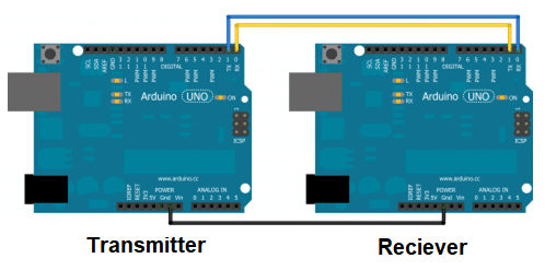
Arduino has the capability to communicate with other devices via UART Protocol. This can be used when connecting one Arduino to another or when connecting an Arduino to a UART compatible module like HC-05 Bluetooth module. To achieve serial communication, follow the following steps:
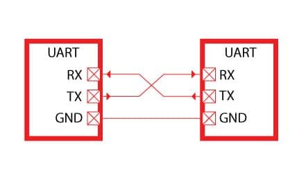
- Connect Tx pin of one Arduino to Rx pin and Rx pin to Tx pin of the other Arduino.
- Connect the grounds of both Arduinos together
UART Transmitter Code for Arduino
As discussed above, when we have to transmit data via serial port, we encode it into data packets. Thankfully, there is a built in Arduino library that does it for us. Lets make an example code that will send a simple “Hello World” to the receiver.
- Initialize the Serial port by calling the function Serial.begin() at a baud rate of 9600bps.. This is done in the setup function because we want to initialize the Serial port only once at the start of the code.
- Transmit the string “Hello World” by calling the function Serial.println() and passing the string “Hello World” to that function.
The basic code looks like this
void setup()

{

  Serial.begin(9600); //Initialize the serial port

}

void loop()

{

  Serial.println("Hello World"); //transmit the string to receiver Arduino

  delay(100); //Wait for 10 milli sec before transmitting it again because we are in the loop() function

}
UART Receiver Code for Arduino
To receive the string transmitted by the transmitter Arduino, we
- Initialize the Serial port by calling the function Serial.begin() at a baud rate of 9600bps. This is done in the setup function because we want to initialize the Serial port only once at the start of the code.
- In the loop() function, we first check whether the transmitter sent any data or not by calling the Serial.available() function. If the data is received by the receiver Arduino, the Serial.available function will output a TRUE and after that we can decode the data packet by using Serial.Read() function.
- Display the decoded data on serial monitor by using Serial.print() function.
The code goes like this
void setup()

{

  Serial.begin(9600);

}


void loop()

{

if (Serial.available()) //If the data is transmitted from the transmitter Arduino, only then the contents of if function will be executed

  {

      Serial.print(Serial.read()); //Print the received byte to the serial monitor.

  }

}
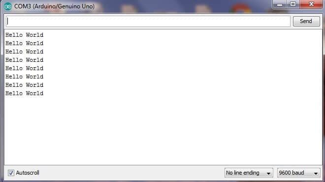
The serial monitor will display
Software Serial UART for Arduino
Arduino has dedicated Tx and Rx pins and it can communicate to only one device at a time via these pins. But what if we want to communicate to multiple devices via Serial Protocol. Well, we can do that by creating a software serial in which any of the digital pins of Arduino can transmit and receive data via Serial protocol.
Software UART Library
To achieve this, the following steps are taken
- Include the software serial library by using the command #include <SoftwareSerial.h>
- Initialize the pins that want to use for Software Serial communication and create object of the class SoftwareSerial. The object can be named whatever you want and is used to differentiate the software serial and the built-in hardware serial of the Arduino that we discussed before in this article. If, for example, we want the pin 2 to be Receiver line Rx and pin 3 to be Transmission line Tx and, we initialize by calling SoftwareSerial class and initializing object by the name of newserial.
- Call the newserial.begin(9600) in the setup function to set the baud rate at 9600bps.
- Transmit a string “Hello World” by calling the function newserial.print(“Hello World”) in the loop function.
The code goes like this
#include <SoftwareSerial.h> //Include Software serial library

SoftwareSerial newserial(2, 3); //Initialize the object newserial and set pin 2 as Rx and 3 as Tx

void setup()

{

  newserial.begin(9600); //Set baud rate of software serial at 9600bps

}

void loop()

{

  newserial.println("Hello World"); //Print the received byte to the serial monitor.

}
If we run the same code on receiver Arduino that we ran before, we would get the same output.
Other Serial communication Protocols:
Practical Tutorials and Projects
The following articles contains examples of UART Serial communication use:
- MSP430 Serial communication module use with examples
- Serial communication PIC microcontroller
- UART Communication with 8051 microcontroller
- How to receive Arduino data through Serial communication in Labview
- Bluetooth module interfacing with Arduino via UART
- Bluetooth module HC 05 interfacing with pic microcontroller
- Control 2 DC Motors via Serial Bluetooth and Arduino
- Serial Bluetooth based dc motor speed and direction control using arduino
- Serial Bluetooth Controlled Robot using pic microcontroller
- Bluetooth based home automation system using android phone