SERIAL COMMUNICATION USING PIC16F877A MICROCONTROLLER, In this tutorial you will learn what is serial communication? What are applications of serial communication? How serial communication pins of PIC16F877A microcontroller is used to transmit and receive data to and from other devices. Lets start with basic introduction of serial communication. Serial communication has many applications it is used to transmit data between pic microcontroller and gsm module. It has many applications in pic microcontroller based projects. I will recommend you to check full list of pic microcontroller guides for beginners.
What is serial communication ?
Unlike parallel communication, where several bits are send at one time, Serial Communication is a process of transmitting data bit by bit. In this tutorial, you will learn how to serially communicate a PC or any other device with a PIC microcontroller. You will also study the use of a communication component – UART (Universal Asynchronous Receiver Transmitter) present within the microcontroller.
Serial vs Parallel Transfer
Computers transfer data in two ways: serial and parallel. In serial Communication, only a single wire is required to transfer n bits of data or one or two wires for ready and acknowledge signals whereas in parallel communication, n wires are required to transfer n bits of data. Serial mode is used to transfer data to greater distances and parallel only works for short distances. Since more hardware is required in parallel communication mode, hence, serial communication is preferred.In data Transmission, if data can both be transmitted and received, it is a duplex transmission. In contrast, a simplex transmission only sends data from one device to the other such as from computer to printer. Duplex Transmission can be Half or Full duplex depending upon whether the data transfer is simultaneous or not. If data is transmitted one way at a time, then it is half duplex. If data can go both ways at the same time then it is Full duplex. PIC microcontroller has a full-duplex, serial mode of Communication.Half and Full-Duplex Transmission
Data Transfer Rate – Baud Rate
The rate of data in serial data communication is known as bits per second or bps. Usually Baud rate is used instead. However, the baud rate and bps are not necessarily equal. This is because baud rate is a modern terminology and is defined as the number of signal changes per second. In modems, sometimes a signal change of signal transfers several bits of data. So there is small difference between bit rate (bps) and baud rate.
Different Serial Communication Protocols
Different protocols are used in data communication for efficient transfer of data between different devices. Some of the serial protocols include RS232, Ethernet, I2C, I2S, PCI, PCI Express, USB etc.
In this lab we will be using RS-232 standard protocol.
PC Serial Port vs Microcontrollers Serial Port
This method of serial communication used by a uController is referred to as TTL serial (transistor-transistor logic). Serial communication at a TTL level will always remain between the limits of 0V and Vcc, which is often 5V or 3.3V..
So, you may see where the problem lies in interfacing these two signals. To connect these two ports you not only have to invert the signals, but you also have to deal with regulating the potentially harmful RS-232 voltages to something that won’t destroy a microcontroller’s serial pins. There are a handful of solutions to this problem of voltage converting and inverting. The most common, and easiest solution is just plugging a MAX-232 in between the two devices:
Most modern computers are not equipped with a serial port. So we use a USB to RS-232 convertor to give them serial communication capability. The Voltage levels of RS-232 (serial) are different from UART of a microcontroller, so we also need a voltage level translator like MAX-232 in-between RX and TX of PC and uController. Fortunately for you, the lab boards you have been using already has this circuit printed on them.The Circuit
TASK
To perform serial communication using PIC16F877A: Serial Communication is the process of sending data one bit at a time. It is achieved by using the UART feature within the pic microcontroller. UART (Universal Asynchronous Receiver Transmitter) is a serial communication interface which is used for transmitting and receiving data. The UART feature is first initialized and then it can be used for transferring data. One of the serial communication architecture includes RS232 standard. It is commonly used in computer serial ports. Using RS232 interface, the communication between a microcontroller and a PC or two microcontrollers can be made possible.
CIRCUIT DIAGRAM :
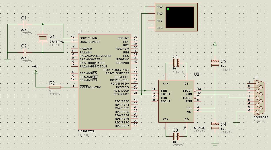
In order to make the communication possible between PIC and a PC, a DB9 connector (female) is used as shown in the schematic, whose male part is connected to the PC. The voltage levels of RS232 protocol are different from that of UART. The voltage level generally used in MCU is HIGH=5V and LOW=0V. Whereas the RS232 working voltages are HIGH=+12V and LOW=-12V.
In order to use the RS232 protocol, we will need a level converter. A level converter will convert the ±12V coming from PC into 5V which can be fed to the controller and vice versa. The level converter used here is called ICMAX232. All the connections of IC with the controller and also with the DB9 connector are shown in the circuit diagram above. RC6/TX and RC7/RX pins of the microcontroller are connected to the T1IN and R1OUT pins of the ICMAX232 respectively. Similarly, the T1OUT and R1IN pins of MAX232 are connected to the DB9 pins 2 (RX) and 3(TX) respectively. Pin 5 of the DB9 connector is grounded. A virtual terminal is connected to the RX and TX pics of the microcontroller to display the transmitting and receiving data.
Serial communication video lecture
C-CODE FOR SERIAL COMMUNICATION USING PIC MICROCONTROLLER
If you have are new to programming check pic microcontroller programming in c. Write the following code in the Code Editor Window of mikroC compiler.
char data_rd;

void main() {

UART1_Init(19200); // Initialize UART module at baud rate 19200 bps

Delay_ms(100); // Wait for UART module to stabilize

UART1_Write_Text("Enter Data");

UART1_Write(10);// moving one line forward

UART1_Write(13);// carriage return

while (1) { // loop executed infinite times

if (UART1_Data_Ready()) { // If data is received from PC

data_rd = UART1_Read(); // read the received data

UART1_Write(data_rd);  // send data via UART

}

}

}
MikroCcompiler has built-in library routines for PIC UART that makes it possible to work with the Asynchronous mode comfortably.In the beginning of the code, a variable of type character – ‘data_rd’ has been declared which holds the value received from PC. You can use a terminal program on PC to transmit and receive data. The baud rate of UART is set to 19200bps in the program. 19200 is the number of bits sent over a serial line per second.The while loop receivesthe data from the PC, stores it in the variable ‘data_rd’ and then sends it again to the terminal on PC.
APPLICATIONS of serial communication :
In this day and age, serial communication is used in various industrial projects where data needs to be collected from different devices. HMI used in banks, marts, industries etc are also serially interconnected.
Serial communication example 2
This code will write “microocontrollers lab” on serial terminal with a delay of four seconds. Delay is generated using timers of pic microcontroller.
void interrupt(){
if (TMR0IF_bit){
 UART1_Write_Text("Bershgal");
 TMR0IF_bit = 0;
 TMR0L = 0x7E;
 TMR0H = 0x13;
}
}
void main() {
ANSELA = 0;
ANSELB = 0;
ANSELC = 0;
ANSELD = 0;
ANSELE = 0;

OSCCON.IRCF0 = 0;
OSCCON.IRCF1 = 1;
OSCCON.IRCF2 = 1;
UART1_Init(9600);

GIE_bit = 1;
TMR0L = 0x7E;
TMR0H = 0x13;
T0CON = 0b10000111;
TMR0IE_bit = 1;
while(1);
}
To download circuit diagram and code of serial communication tutorial using pic microcontroller,Click on following link. Kindly take few seconds to share this article with your friends on social media. Thanks 🙂
you didnt tell us how to send data through PIC to PC
please how did you do it send data through pic to pc??
Hi
you can use any RS232 converter or USB to ttl FTDI converter. You can check this post:
http://microcontrollerslab.com/arduino-usb-ttl-converter-three-ways-use/
what if the data is analog and we need to digitize it and send it to PC?
i can transfer data successfully but it’s transfer garbage values
Where i can enter the data to transimitt it , if am using a proutos progamm , and how i can transmit it , can i replace the vertial termenant by using LCD screen?, or to replace it by just a progamm in the computer that show the transmitted and recsived data ??
How to send two 10 bit ADC data and two 1 bit digital data simultaneously via usart ?
adc data rate is two per second.
Thanks,
Papendu