In this tutorial, we will learn about HC-05 Bluetooth to serial port module and how to interface it with Arduino. This Bluetooth device operates on UART communication. In other words, it uses serial communication to transmit and receive data serially over standard Bluetooth radio frequency. Therefore, we will use TX, RX pins of Arduino to connect with the module.
In this tutorial, we will use an android application to communicate with the Arduino through the HC-05 Bluetooth module. We will see an example to control an LED from the Android application using Bluetooth wireless communication. The LED will be connected with a GPIO pin of the Arduino and in effect, we will be controlling that pin.

Recommended Components
The following components are used in this project or are helpful for building it with the Arduino.
| Component | How it’s used in this project | Buy on Amazon |
|---|---|---|
| Arduino Uno R3 | The main controller board that runs the sketch and drives all the components in this project. | Check Price |
| HC-05 Bluetooth module | Provides the wireless serial link used to send commands to the Arduino. | Check Price |
| 5mm LED | The output that is switched on and off over the Bluetooth connection. | Check Price |
| Resistor kit (220Ω) | A 220Ω resistor limits the current through the LED. | Check Price |
| Breadboard | Lets you build and prototype the circuit without soldering. | Check Price |
| Jumper Wires | Used to make all the connections between the Arduino and the components. | Check Price |
As an Amazon Associate we earn from qualifying purchases. Prices and availability are accurate as of the date/time indicated and are subject to change.
Bluetooth Classic Introduction
Bluetooth is a way of communication which makes the world wonder about it. Bluetooth is now provided in everything which is designed for some type of communication. It is available from smartphones to self-driving vehicles systems. It has interesting history and working system, which proves how versatile it is. It is managed by the Bluetooth Special Interest Group, which set the standards, advance the Bluetooth capabilities.
Bluetooth was invented by a telecom specialist Ericsson in1994. It is an alternate of the RS-232 cables. It created above mentioned body which is supported by Intel and takes care of development and licensing. Any company who want to use the standards or market products with the technology is required to become the member of above committee. The Promoter members are:
- Ericsson
- Intel
- Microsoft
- Nokia
- Lenovo
- Toshiba
- Motorola

How the name Bluetooth came to being? Ericsson, the company that started Bluetooth is from Sweden, which is part of the Scandinavian region, a historical and cultural-linguistic part of Europe. The name comes from an epithet of a tenth-century King of Denmark and Norway named Harald “Bluetooth” Gormsson. In the local language, he was called Blåtand or Blåtann, which translated in English, became ‘Bluetooth’. He was known for uniting the Vikings in ages past, from which the idea of the communication standard came, something that was a single unifying standard for mobile technologies. The logo, in fact, is a combination of two Nordic runes called ‘Hagall’ and ‘Bjarkan’, which were the initials of King Harald “Bluetooth” Gormsson.
How Does Bluetooth Work?

Bluetooth operates in the standard Industrial, Scientific and Medical (ISM) short range frequency band of 2.4 GHz. Specifically, it operated in the 2400–2483.5 MHz frequency band, which includes guard bands as well. It uses something called Frequency Hopping Spread Spectrum (FHSS), which is basically a multiple access method in which data packets are divided based on frequency over 79 designated Bluetooth channels. Each channel has a bandwidth of 1 MHz. The newer Bluetooth 4.0 standard, however, uses 2 MHz steps and thus has 40 designated channels. It uses a variation of FHSS called Adaptive Frequency-hopping spread spectrum (AFH), which theoretically skips channels with interference and results in better communication.
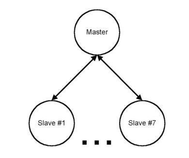
Bluetooth is essentially a protocol with a master-slave architecture, which means that one master device can communicate with up to 7 devices. This was and is a huge advantage to earlier wired communication protocols which could work only with a 1 to 1 configuration. Essentially creating a new standard called Personal Area Networks (PANs), Bluetooth brought about far more effective ad-hoc networks and allows communication without traditional host based networking.
Bluetooth Terminal Application
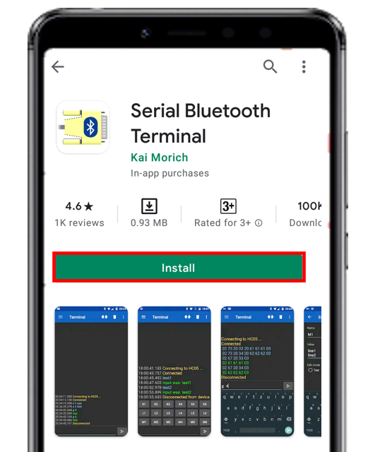
Throughout this guide, we will use an android smartphone that will connect to our ESP8266 development board. So, make sure you have an android phone at hand. We will also use a Bluetooth terminal application to pair the two devices together.
Go to the Play Store and download the application by the name: Serial Bluetooth terminal. This can be seen in the figure below.
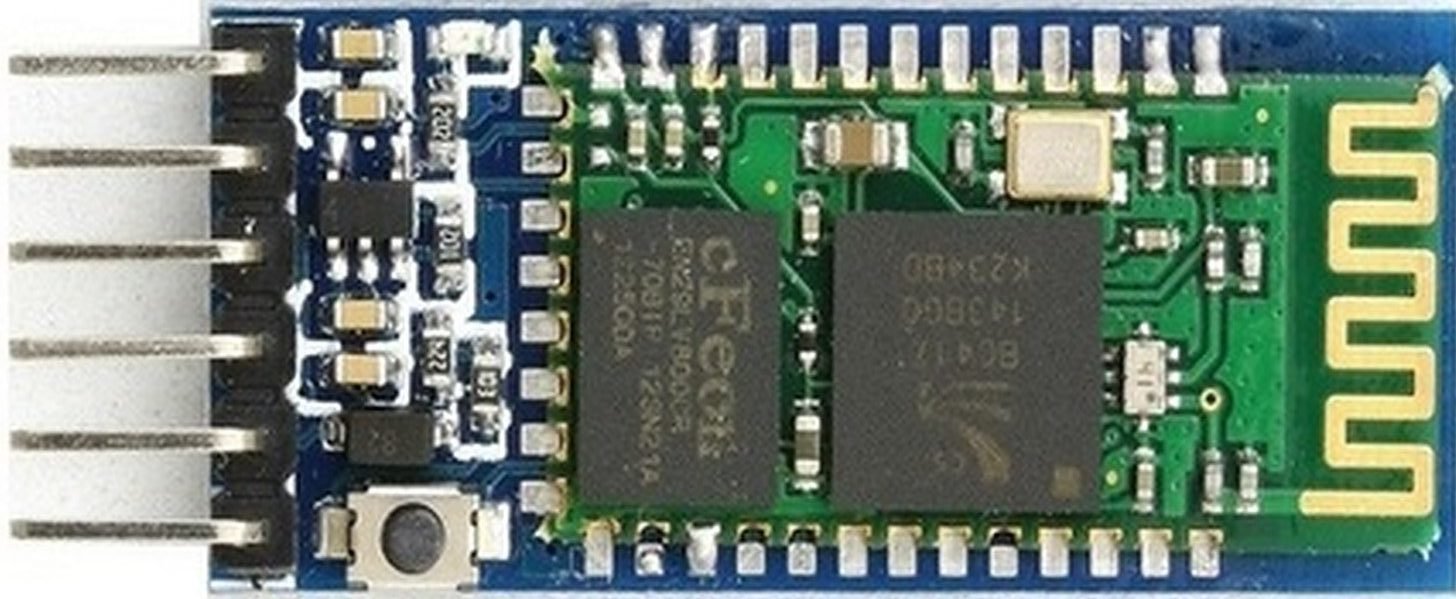
HC-05 Introduction
HC-05 is one of the commonly used Bluetooth device that uses a UART communication protocol. The HC-05 Bluetooth is much different in features from all other Bluetooth devices because of its multiple pins and their functions. It has multiple pins for the different method which makes it unique as compared to others. The module normally operates at UART serial communication with TX and RX pins at 9600 baud rates. However, it can be programmed with AT commands and it supports 9600,19200,38400,57600,115200,230400,460800 baud rates.
Its CSR Bluecore 04-External single chip is already configured to communicate with other Bluetooth devices through serial communication. It offers a two-way communication method and the HC-05 can act as either slave and master. The Bluetooth module offers only short distance communications due to its limitation but still, most of the devices come with it due to its speed and security. The limitation of this device is that it doesn’t allow to transfer any kind of media.
In short, this module can be used to perform low-cost wireless communication between microcontrollers such as Arduino, TM4C123, Pic Microcontroller, Raspberry Pi, BeagleBone, STM32, and Arduino Mega, etc. Also, we can use it for communication between a microcontroller and PC or Android application. There are many Android applications available in the Google Play store which we can use to send and receive data to/from HC05. For this tutorial, we will use ‘Serial Bluetooth Terminal’ application that we installed previously.
Recommended Reading: HC-05 Bluetooth Module
Pinout
The HC-05 comes with multiple pins and indicators, which helps to control different operations and view their states through indicators. This pinout diagram provides indications of all pins.
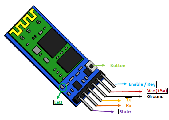
The table below also briefly describes the functionality of each pin.
| Pin | Description |
| VCC | The operating voltage range is 3.3 volts. But I/O pins can withstand voltage of up to 5 volts. Therefore, we can connect 5 volts power source to this pin, and also other pins can also operate on 5 volts signals such as Tx and Rx signals. |
| GND | Ground reference of both ESP8266 and HC-05 should be at the same level. Therefore, we should connect a power supply, HC05, and ESP8266 ground pins to each other. |
| Tx | As discussed earlier, the HC-05 Bluetooth module uses UART communication to transmit data. This is a transmitter pin. The TX pin will be the data transfer pin of the module in UART. |
| Rx | This pin is a data receiving the pin in UART communication. It is used to receive data from the microcontroller and transmits it through Bluetooth. |
| State | The state shows the current state of the Bluetooth. It gives feedback to the controller about the connectivity of Bluetooth with another device. This pin has an internal connection with the onboard LED which shows the working of HC05. |
| Enable/Key | Using an external signal, Enable/Key pin is used to change the HC-05 mode between data mode and command mode. The HIGH logic input will transfer the device in command mode and the LOW logic input will change the mode to data mode. By default, it works in data mode. |
| Button | The command and data mode states are changeable through a button present on the module. |
| LED | This pin shows the working status of module along with the State pin |
Interfacing HC-05 with Arduino

Connect the circuit as follows:
- Bluetooth Tx with Arduino UNO Rx (D0)
- Bluetooth Rx with Arduino UNO Tx (D1)
- Bluetooth VCC with Arduino UNO +5V
- Bluetooth GND with Arduino UNO GND
- No need to connect any other pin as given in figure.
NOTE: Make sure you plug out the Tx and Rx pins out of Arduino before uploading the program. After uploading the program connect them back. Otherwise, you can get an error.
Code for HC-05 Bluetooth module interfacing with arduino
int LED = 13; //led pin
int info = 0; //variable for the information comming from the bluetooth module
int state = 0; //simple variable for displaying the state
int checking = 8;
void setup() {
Serial.begin(9600); //making serial connection
pinMode(LED, OUTPUT); //defining LED pin
digitalWrite(LED, LOW); //once the programm starts, it's going to turn of the led, as it can be missleading.
pinMode(checking, OUTPUT);
}
void loop() {
int sta = digitalRead(checking);
//Serial.println(sta);
if (Serial.available() > 0) { //if there is any information comming from the serial lines...
info = Serial.read();
state = 0; //...than store it into the "info" variable
}
if (info == '1') { //if it gets the number 1(stored in the info variable...
digitalWrite(LED, HIGH); //it's gonna turn the led on(the on board one)
if (state == 0) { //if the flag is 0, than display that the LED is on and than set that value to 1
Serial.println("LED ON"); //^^that will prevent the arduino sending words LED ON all the time, only when you change the state
state = 1;
}
} else if (info == '0') {
digitalWrite(LED, LOW); //else, it's going to turn it off
if (state == 0) {
Serial.println("LED OFF"); //display that the LED is off
state = 1;
}
}
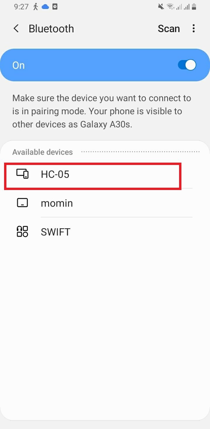
}In your smartphone settings, enable Bluetooth and scan for available Bluetooth devices. You will see the HC-05 device in your scanned list. The default name for this Bluetooth device is “HC-05” and the default pin code is either “0000” or “1234”.
Setting up Android App
We will use an android smartphone to connect with our ESP8266 module. To do that you will have to perform a series of steps.
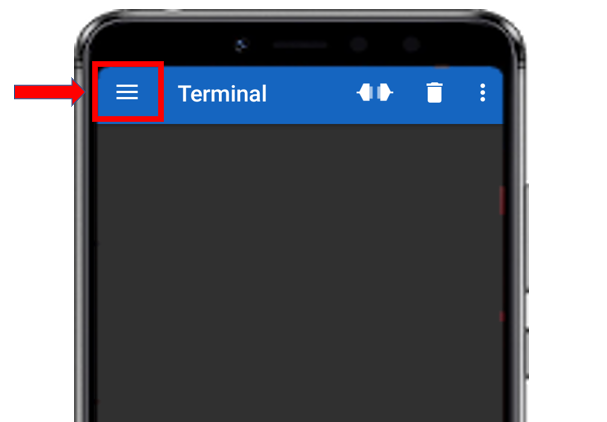
After you have installed the ‘Serial Bluetooth Terminal app, open it. On the top left corner of the screen, you will find three horizontal bars. Tap it.
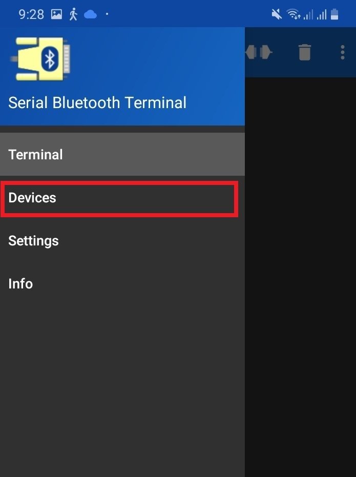
Now, tap on the Devices tab.
In the ‘available devices’ section, select ‘HC-05’
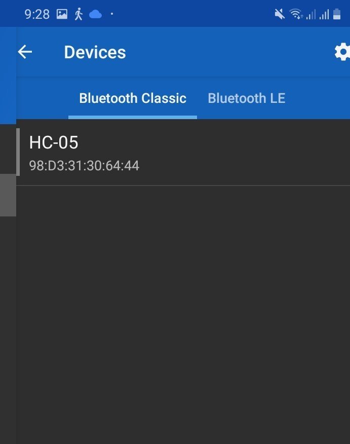
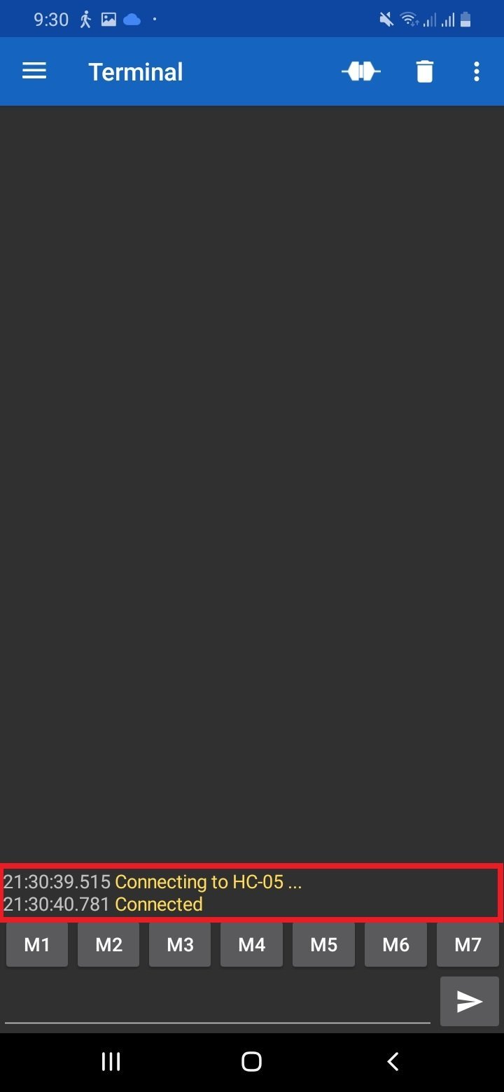
After you have selected the HC-05 module then tap the ‘link’ icon at the top of the screen. At first, you will get the message: ‘Connecting to HC-05.’ After a successful connection, you will get the message: ‘Connected.’
Follow these steps to control LED:
- Download the “Bluetooth Terminal” App from Android playstore on your android phone.
- Open the app and connect with HC-05 Bluetooth.
- Send 1 to turn on the LED.
- Send 0 to turn off the LED.
For the demo, you can see the video given below:
You may like to read:
- HC-05 Bluetooth Interfacing with TM4C123G Tiva C Launchpad – Keil uvision
- HM-10 Bluetooth Module – Interfacing Example with Arduino
- HC-05 Bluetooth Interfacing with ESP8266 NodeMCU – Control GPIO Pins
- Introduction to Bluetooth Low Energy
- Control 2 DC Motors via Bluetooth and Arduino
- Bluetooth Based Home Automation
- Bluetooth based dc motor speed and direction control using Arduino
- HC-05 Bluetooth module interfacing with Arduino
- Bluetooth module HC 05 interfacing with pic microcontroller
- Bluetooth Controlled Robot using pic microcontroller