In this tutorial, we will learn how to interface a buzzer module with Arduino. A buzzer module is an integrated device that uses a DC power supply and electronic transducers to produce sound. These are widely used in other electronic applications, such as timers, alarms, electronic toys, computers, telephones, and many more products, wherever we require sound generation. Buzzers are of two types: active buzzers and passive buzzers. Before diving deep into the details of active and passive buzzers, we will first see what a piezoelectric buzzer is and how it works.
Recommended Components
The following components are used in this project or are helpful for building it with the Arduino.
| Component | How it’s used in this project | Buy on Amazon |
|---|---|---|
| Arduino Uno R3 | The main board that runs the sketch and controls all the components in this project. | Check Price |
| Buzzer module | Active buzzer driven by the Arduino to produce audible tones and alerts. | Check Price |
| Breadboard | A solderless breadboard for prototyping and wiring the circuit without soldering. | Check Price |
| Jumper Wires | Male-to-male jumper wires to connect the Arduino to the breadboard and modules. | Check Price |
As an Amazon Associate we earn from qualifying purchases. Prices and availability are accurate as of the date/time indicated and are subject to change.
Piezoelectric Buzzer
A piezoelectric buzzer uses the piezoelectric effect to generate sound waves. The piezoelectric effect is a phenomenon in which mechanical stress is applied to a certain material, and when mechanical stress is applied to this material, an electric charge is produced across this material. At this time, when an electrical charge is also applied to this material, it starts to deform and vibrate. This phenomenon is used to make sounds using buzzers and many other devices.
Working principle of Piezoelectric Buzzers
Here we will explain the working principle behind the piezoelectric buzzers. A general piezoelectric buzzer uses a ceramic disc or element placed between two metal plates. When an electric supply is provided to these metal plates, they get charged, which forces the ceramic element to contract and expand due to the electric field produced around it by these metal plates. In case you are interested and want to, we have provided a link here: Arduino Piezo Buzzer Document.
This mechanical stress and deformation of the ceramic element produce vibrations. These vibrations are passed through the air as sound waves, and we hear them as audible sounds or tones. These elements will keep making sounds until an electric current is provided to the metal plates. This simple design makes piezoelectric buzzers compact and more power-efficient. This makes them quite popular, and they are used across a variety of equipment, including medical instruments and kid’s toys, to name a few.
Types of Piezoelectric Buzzers
Generally, there are two types of piezoelectric buzzer modules:
- Active Buzzer modules
- Passive Buzzer modules
We have provided a simple comparison between these two types of piezoelectric buzzers in the table below.
| Type of Module | Working Functionality |
| Active Buzzer | An active buzzer generates the sound by itself. We just have to provide the electric current using the Arduino pin and turn the logic HIGH and LOW, similar to the blink example of an LED. |
| Passive Buzzer | A passive buzzer, on the other hand, requires a pulse signal to produce the sound. This sound can be controlled using PWM (Pulse Width Modulation) on the Arduino board. The passive buzzer has various applications and can be used to play music. |
Note: The above table provides information for a general buzzer module. However, some buzzers require more current than the Arduino digital pin provides. In this case, we can use an external power circuit by connecting the MOSFET to our circuit and amplifying the current to the buzzer.
If you are interested in using the buzzer module with the PIC microcontroller, click the link below:
Hardware Components:
Here we have listed the hardware components we will be using in this tutorial:
- Arduino UNO Board
- Active Buzzer – KY-012
- Passive Buzzer – KY-006
- Jumper wires
YouTube Video:
Active Buzzer
An active buzzer generates sound when an electric current is provided to it, as mentioned above. This type of buzzer has an internal oscillator circuit that drives the piezoelectric element to produce the sound without requiring an external PWM signal source. When the active piezoelectric buzzer receives DC voltage, it starts to emit a sound.
One thing to note is that the active buzzer generates sound only at an audible frequency of 2.5 kHz. So, the active buzzer is unable to produce different sounds or melodies.
Specifications of Active Buzzer Module
We have provided the specifications of the active buzzer module below:
- It operates at a voltage range of 3.3V–5V DC.
- This buzzer module has a current rating of 30 mA at 5V DC.
- The resonance frequency of this buzzer is between 2500Hz ± 300Hz.
- It has a small size: 3.3 x 1.3 x 1.2 cm.
Active Buzzer Module Pinout Diagram
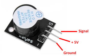
This active buzzer module (KY-012) has only three pins. The functions of these pins are provided in the table below:
| Module Pin | Function of Pin |
|---|---|
| S or Signal | The signal pin provides the electric signal to drive the buzzer. |
| VCC or + | This module has no + or VCC pin, as the signal pin provides the voltage for the buzzer to work. |
| GND or – | The left-most pin is the ground pin of this active buzzer module. |
Schematic of Active Buzzer Module Interfacing with Arduino
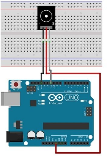
In this section, we have provided the schematic diagram. This schematic diagram helps us properly connect our Arduino Board to the KY-012 buzzer module.

The wiring schematic is very simple. We have connected the GND pin of the KY-012 Buzzer Module to the GND pin of our Arduino Board. Then we connected the middle pin to 5V, and at last we connected the S pin to pin 11 of our Arduino Board. These connections can be seen in the schematic above.
Arduino Sketch – Active Buzzer
Open the Arduino IDE and go to File > New to create a new file. Now copy this sketch given below and paste it in the Arduino File. Select the COM port of the connected Arduino board and click Upload. This will upload the sketch to the Arduino board. If you have followed the tutorial correctly, the buzzer will start producing sound at 2 kHz frequency.
// This code is for testing the active buzzer

int buzzerPin = 11;  // initializing the buzzer pin at pin 11 of Arduino

void setup() {           // Code written in it will only run once

  pinMode(buzzerPin, OUTPUT);   // This will set the pin 11 as output

  beep(50);                 // This will make a beep sound Beep

  beep(50);

  delay(1000);            //Adding a delay of 1 sec.

}

void loop() {             // Code written in it will run continuously

  beep(50);               // This will make a beep sound after every 500 milliseconds

  delay(1000);         // Adding a delay of one second.

}

void beep(unsigned char delayms) {       // Created a function for beep

  analogWrite(buzzerPin, 20);                   // This will set pin 11 to high

  delay(delayms);                                        // Giving a delay

  analogWrite(buzzerPin ,0);                    // This will set pin 11 to LOW

  delay(delayms);                                     // Giving a delay

}
Sketch Explanation
In this section, we are going to look at the above code and try to explain how each part works.
int buzzerPin = 11; // initializing the buzzer pin at pin 11 of ArduinoAt first, we assign the pin that will power the buzzer.
void setup() {           // Code written in it will only run once

  pinMode(buzzerPin, OUTPUT);   // This will set the pin 11 as output

  beep(50);                 // This will make a beep sound Beep

  beep(50);

  delay(1000);            //Adding a delay of 1 sec.

}
In the void setup() function, we set the buzzer pin as the output using the pinMode() function. Then we use the beep function() with a parameter of 50 and a delay of 1 sec, or 1000 ms.
void loop() {             // Code written in it will run continuously

  beep(500);               // This will make a beep sound after every 500 milliseconds

  delay(1000);         // Adding a delay of one second.

}
The void loop() function runs the code continuously. So, in this section, we have again called the beep function with parameter 50. This parameter will delay the beep sound for 500 ms every time beep(500) calls the function.
void beep(unsigned char delayms) {                       // Created a function for beep

  analogWrite(buzzerPin, 20);                                      // This will set pin 11 to high

  delay(delayms);                                                                // Giving a delay

  analogWrite(buzzerPin ,0);                                      // This will set pin 11 to LOW

  delay(delayms);                                                             // Giving a delay

}
At last, we have the beep() function. In this function, we use the analogWrite() function to set the buzzer pin of the Arduino (pin 11) to HIGH. then a delay of 500 ms using the function argument, and then we set the buzzerPin (pin 11) to LOW, again using the analogWrite() function along with another delay of 500 ms. This function ends, and the program again moves to the void loop() function. This cycle keeps repeating itself continuously.
Passive Buzzer
In this section, we will be discussing passive buzzers. As explained earlier, a passive buzzer requires an external signal to generate sound. This is because the passive buzzer does not have an internal oscillator, unlike active buzzers. This means that passive buzzers are unable to produce sounds on their own when DC voltage is provided. To drive the buzzer, we have to provide it with an external PWM signal or a simple ON/OFF signal with varying frequencies to generate the sound using the Arduino board.
This varying-frequency signal can be in the range of 1.5 kHz to 2.5 kHz. By using this versatility, we are able to generate different sounds or melodies using this passive buzzer module. By using the PWM signal, we are controlling the piezoelectric elements vibrating speed.
Specification of Passive Buzzer Module
We have provided the specifications of passive buzzer module below:
- It operates at a voltage range of 1.5V–5V DC.
- The Tone generation range of KY-006 Module is between 1.5 kHz and 2.5 kHz.
- It has a small size: 18.5mm x 15mm [0.728in x 0.591in].
Passive Buzzer Module Pinout Diagram
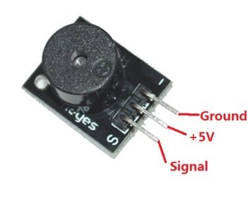
This passive buzzer module (KY-006) has only three pins. The functions of these pins are provided in the table below:
| Module Pin | Function of Pin |
| S or Signal | The signal pin provides the PWM signal to drive the buzzer and produce the different sounds or melodies. |
| VCC or + | This module has no + or VCC pin, as the signal pin provides voltage for the buzzer to work. |
| GND or – | The right-most pin is the ground pin of this passive buzzer module. |
Schematic of Passive Buzzer Module Interfacing with Arduino
In this section, we have provided the schematic diagram. This schematic diagram helps us properly connect our Arduino Board to the KY-006 buzzer module.
The wiring schematic is very simple. We have connected the GND pin of the KY-012 Buzzer Module to the GND pin of our Arduino Board. Then we connected the middle pin to 5V, and at last we connected the S pin to pin 11 of our Arduino Board. These connections can be seen in the schematic above.
Arduino Sketch – Passive Buzzer
Open the Arduino IDE and go to File > New to create a new file. Now copy this sketch given below and paste it in the Arduino File. Select the COM port of the connected Arduino board and click Upload. This will upload the sketch to the Arduino board. If you have followed the tutorial correctly, the buzzer will start producing different sounds.
// This code is for testing the passive buzzer

int out =11;    // initializing pin 11 as buzzer pin

void setup ()    // Code written in it will only run once.
 {
   pinMode(out, OUTPUT);   // Setting pin 11 as output pin
 }

void loop ()                 // Code written in it will run repeatedly
 {
   unsigned char i, j ;        // Declaring variables
   while (1){
     for (i = 0; i <80; i++){              // 100 cycles of sound
       digitalWrite (out, HIGH);    // This will turn the buzzer ON
       delay (1) ;                             // Giving a Delay of 1ms will set frequency 1
       digitalWrite (out, LOW);    // This will turn the buzzer OFF
       delay (1) ;                           // Giving a delay ms
     }
     for (i = 0; i <100; i++){        // 100 cycles of sound
       digitalWrite (out, HIGH);    // This will turn the buzzer ON
       delay (2) ;                            // Giving a delay of 2ms will set frequency 2
       digitalWrite (out, LOW);             // This will turn the buzzer OFF
       delay (2) ;                                     // Giving a delay of 2ms
     }
   }
 }
Sketch Explanation
In this section, we will explain the workings of the above code.
int out =11; // initializing pin 11 as buzzer pinIn this code, we have set the signal pin to pin 11 of the Arduino board.
void setup ()    // Code written in it will only run once.
 {
   pinMode(out, OUTPUT);   // Setting pin 11 as output pin
 }
The void setup() function, we have initialized the pin mode of pin 11 as output using the pinMode() function.
void loop ()                 // Code written in it will run repeatedly
 {
   unsigned char i, j ;        // Declaring variables
   while (1){
     for (i = 0; i <80; i++){              // 100 cycles of sound
       digitalWrite (out, HIGH);    // This will turn the buzzer ON
       delay (1) ;                             // Giving a Delay of 1ms will set frequency 1
       digitalWrite (out, LOW);    // This will turn the buzzer OFF
       delay (1) ;                           // Giving a delay ms
     }
     for (i = 0; i <100; i++){        // 100 cycles of sound
       digitalWrite (out, HIGH);    // This will turn the buzzer ON
       delay (2) ;                            // Giving a delay of 2ms will set frequency 2
       digitalWrite (out, LOW);             // This will turn the buzzer OFF
       delay (2) ;                                     // Giving a delay of 2ms
     }
   }
 }
In the void loop() function, we have used two for loops. The first one goes up to 80 iterations; in this loop, the buzzer turns ON and OFF with a delay of 1 ms. The second loop goes up to the 100th iteration; the buzzer turns ON and OFF with a delay of 2 ms in this loop.
Playing a Melody using Passive Buzzer Module
In this example, we will play a melody using the passive buzzer. We will use the capability of Arduino to produce the PWM signal through which the buzzer will generate tones at different frequencies. The connections are the same as we did for the passive buzzer. Just upload the code, and the buzzer will play a melody.
Melody Game – Arduino Sketch
// This code is for playing a melody

int buzzerpin = 11;
 int DEBUG = 1;

 void setup() {
   pinMode(buzzerpin, OUTPUT);     // Setting pin 11 as output
   if (DEBUG) {
     Serial.begin(9600);     // Setting baud rate at 9600
   }
 }


 int melody[] = {  C,  b,  g,  C,  b,   e,  R,  C,  c,  g, a, C };  // initializing variables for playing melody
 int beats[]  = { 16, 16, 16,  8,  8,  16, 32, 16, 16, 16, 8, 8 };   // initializing the beat values
 int MAX_COUNT = sizeof(melody)


 long tempo = 10000;   // This will Set overall tempo

 int pause = 1000;        // initializing the variable for pause between tones

 int rest_count = 100; //<-BLETCHEROUS HACK; See NOTES

 // Initialize core variables
 int tone_ = 0;
 int beat = 0;
 long duration  = 0;

 // PLAY TONE  ==============================================
 // Pulse the speaker to play a tone for a particular duration
 void playTone() {
   long elapsed_time = 0;
   if (tone_ > 0) { // if this isn't a Rest beat, while the tone has
     //  played less long than 'duration', pulse speaker HIGH and LOW
     while (elapsed_time < duration) {

       digitalWrite(buzzerpin,HIGH);
       delayMicroseconds(tone_ / 2);

       // DOWN
       digitalWrite(buzzerpin, LOW);
       delayMicroseconds(tone_ / 2);

       // Keep track of how long we pulsed
       elapsed_time += (tone_);
     }
   }
   else { // Rest beat; loop times delay
     for (int j = 0; j < rest_count; j++) { // See NOTE on rest_count
       delayMicroseconds(duration);
     }
   }
 }

 // LET THE WILD RUMPUS BEGIN =============================
 void loop() {
   // Set up a counter to pull from melody[] and beats[]
   for (int i=0; i<MAX_COUNT; i++) {
     tone_ = melody[i];
     beat = beats[i];

     duration = beat * tempo; // Set up timing

     playTone();
     // A pause between notes...
     delayMicroseconds(pause);

     if (DEBUG) { // If debugging, report loop, tone, beat, and duration
       Serial.print(i);
       Serial.print(":");
       Serial.print(beat);
       Serial.print(" ");
       Serial.print(tone_);
       Serial.print(" ");
       Serial.println(duration);
     }
   }
 }
Conclusion:
Here we have provided a summary of the topics we have covered in this tutorial:
- Piezoelectric buzzers and their working principle.
- Types of Piezoelectric buzzers.
- Active buzzers and their example.
- Passive buzzers and their examples.
Related Articles:
If you are interested in reading more similar articles, please check the link below:
- Control 28BYJ-48 Stepper Motor with ULN2003 Motor Driver and Arduino
- Interface nRF24L01+ Wireless Module with Arduino
- TM1637 4 Digit 7 Segment Display Module with Arduino
- KY-038 Microphone Sound Sensor Module with Arduino
- Interface Touch Sensor Module with Arduino
- MAX6675 K-Type Thermocouple with Arduino
- RDM6300 RDM630 RFID Reader interfacing with Arduino
thanks a lot, the blog really helped me, am working on electronic bell system and needed help.