In this tutorial, we will learn how about KY-038 microphone sound sensor module and how to interface it with Arduino. We will show you its pinout and features along with its connection diagrams with Arduino. With the help of two Arduino sketches, we will be able to create a sound detection project whereby a clap sound will toggle the state of a LED connected with the Arduino board.
Let us first learn a little bit about the KY-038 Sound sensor module first.
Recommended Components
The following components are used in this project or are helpful for building it with the Arduino.
| Component | How it’s used in this project | Buy on Amazon |
|---|---|---|
| Arduino Uno R3 | Reads the KY-038 digital/analog output and lights an LED based on detected sound level. | Check Price |
| Breadboard | Holds the KY-038 module, LED and resistor for the sound-indicator demo. | Check Price |
| Jumper Wires | Connect the KY-038 output pins and the LED circuit to the Arduino. | Check Price |
| 5mm LED | An LED driven by the Arduino to indicate when the sound sensor detects noise above the threshold. | Check Price |
| Resistor Kit (220/4.7k) | Provides the current-limiting resistor for the indicator LED. | Check Price |
As an Amazon Associate we earn from qualifying purchases. Prices and availability are accurate as of the date/time indicated and are subject to change.
Introducting KY-038 Sound Sensor Module
The KY-038 sound sensor module consists of capacitance sensitive microphone (50Hz-10kHz) and an amplification circuit. The module converts sound waves to electrical signals.
It detects the sound with the help of a microphone and then feeds this sound to processing circuitry which consists of an operational amplifier LM393. It also consists of a potentiometer which is used for setting the sound level and by setting this sound level the output of this sound sensor module could be easily controlled. Similarly, the output of this sensor could be checked by connecting the LED or any other device at output pins.
There are two types of outputs accessible from this sensor, both digital output and analog output. The digital output is obtained when the sound is at a particular threshold value. The potentiometer is used to adjust the sensitivity of the digital output pin. When a particular sound will be higher/lower than the threshold level, the digital output will be low/high. In our case, the digital output will be HIGH and it will be LOW when the sound will be detected.
However, the analog output depicts the direct microphone signal as a voltage level that changes with the intensity of the sound.
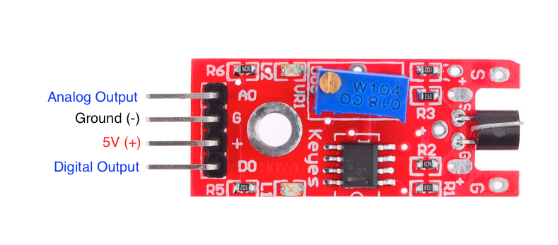
Pinout
The sound sensor module consists of four pins Ao, Vcc, GND, and Do. Ao pin is used of analog output, Vcc pin is used for giving supply voltage to this sound sensor module which is 5V dc. Similarly, a GND pin is used for giving ground to this sound sensor module, and a D0 pin is used for digital output.
The figure of this sound sensor module is shown below:
Interfacing Sound Sensor Module with Arduino
We will require the following components for this project.
Required Components:
- Arduino
- Sound Sensor Module (KY-038)
- Connecting Wires
Note: We will use the digital output pin for this tutorial.
Assemble the devices as shown in the schematic diagram below:
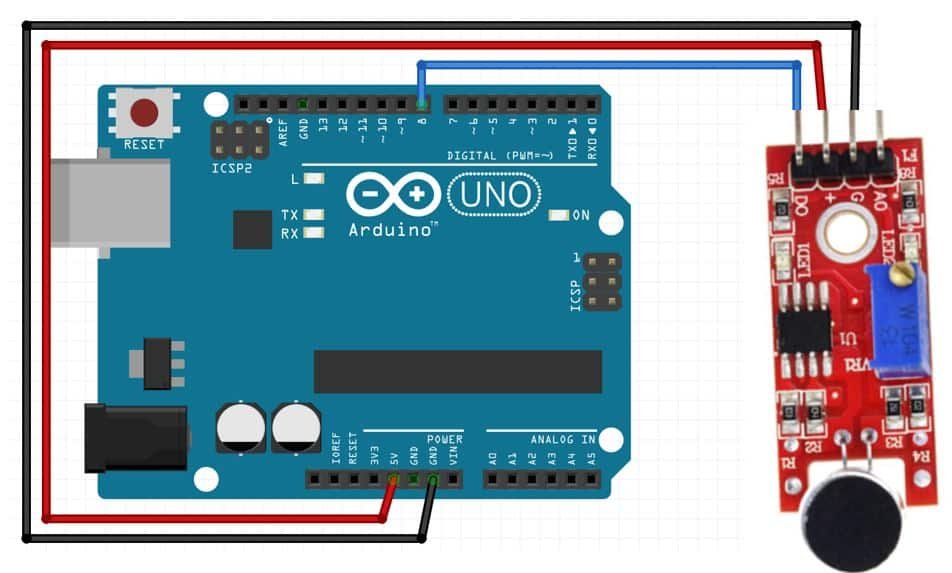
We will connect 3 pins of the KY-038 sound sensor module with Arduino. These include the VCC, GND, and DO pins. The VCC will be connected with the 5V pin from the Arduino. GND of both the devices will be in common. We will connect digital pin 8 with DO.
Arduino Sketch: Calibrating the Sound Sensor Module
Open your Arduino IDE and go to File > New. A new file will open. Copy the code given below in that file and save it.
This code will help us to calibrate our sound sensor module to clap sounds.
#define DO 8
unsigned long last_event = 0;
void setup() {
pinMode(DO, INPUT);
Serial.begin(115200);
}
void loop() {
int output = digitalRead(DO);
if (output == LOW) {
if (millis() - last_event > 25) {
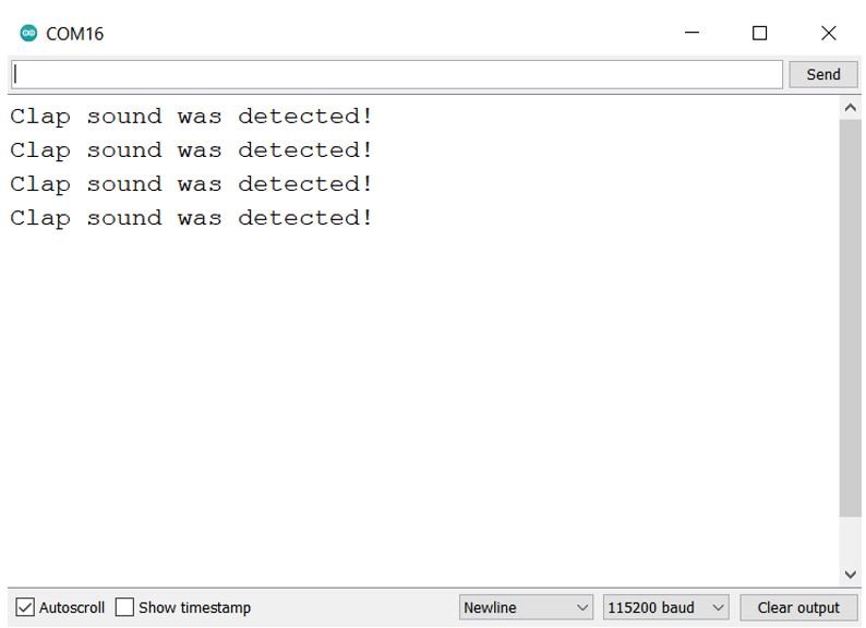
Serial.println("Clap sound was detected!");
}
last_event = millis();
}
}How the Code Works?
Firstly we will define the digital pin that we connected with the digital output (DO) of the sound sensor. It is GPIO8 in our case.
#define DO 8Next, to monitor the clap sounds we will create a variable to store the ‘last_event’. This will store the time since the last clap sound was detected.
unsigned long last_event = 0;Inside the setup() function we will open the serial communication at a baud rate of 115200. Moreover, we will configure the output pin of the sensor as an input pin. This will be achieved by using the pinMode() function and passing DO as the first parameter and ‘INPUT’ as the second parameter.
void setup() {
  pinMode(DO, INPUT);
  Serial.begin(115200);
}
Inside the infinite loop() function, we will first find out the sensor output value using digitalRead(). We will pass the digital pin connected to the sensor as an argument inside it. This will be stored in the integer variable ‘output’.
int output = digitalRead(DO);Then, we will check if the sensor output is LOW or not. Remember the output will be LOW whenever a loud sound will be detected. If the output is indeed LOW and it stays like that for more than 25 milliseconds then the sound is indeed from a clap. Then the serial monitor will display “Clap sound was detected!”
  if (output == LOW) {
    if (millis() - last_event > 25) {
      Serial.println("Clap sound was detected!");
    }
    last_event = millis();
  }
Demonstration
Choose the correct board and COM port before uploading your code to the board.
Go to Tools > Board and select Arduino.

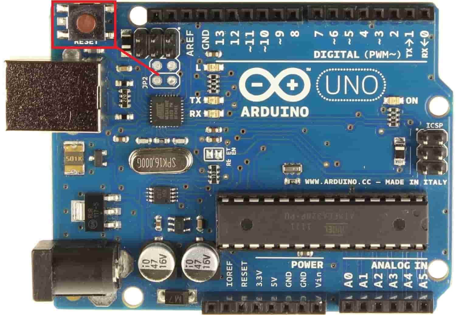
Next, go to Tools > Port and select the appropriate port through which your board is connected. Click on the upload button to upload the code into the Arduino development board. After you have uploaded your code to the Arduino press its RST button.
In your Arduino IDE, open up the serial monitor and set the baud rate to 115200.
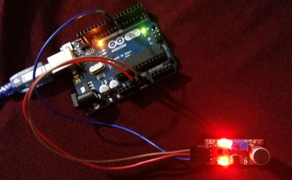
Now clap close to the microphone and notice if the serial monitor detects a clap or not.
You will have to calibrate the sound sensor in order for it to detect the sound precisely. The potentiometer will help us calibrate the sensor. Rotate the potentiometer anticlockwise to increase the sensitivity of the sensor and rotate it clockwise to decrease its sensitivity. Rotating the potentiometer will change the threshold value which will be used to detect the clap sound. When the clap sound is greater than the threshold value set then the output pin goes in a LOW state.
Keep rotating the potentiometer until the clap sound is detected precisely.
Control LED with Clap Sound
Now after successfully calibrating your sensor module it is time to head further and control an LED with the clap sound. In this project, we are keeping it basic and showing you how to control a LED via the sound sensor however you can control any device example buzzer, bulb, etc as well.
You will require the following components for this project.
Required Components
- Arduino
- Sound Sensor Module (KY-038)
- One 5mm LED
- One 220 ohm resistor
- Breadboard
- Connecting Wires
Follow the schematic diagram below to connect all three devices properly.
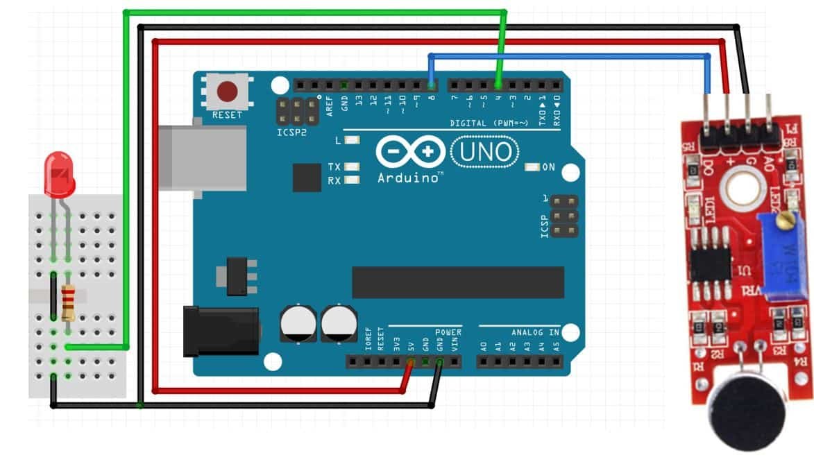
We have connected the LED anode pin with GPIO4 through a 220ohm resistor. Later on, in the program code, we will configure this GPIO pin as a output pin. You can use any appropriate output GPIO pins. The cathode pin is grounded with Arduino ground and sound sensor ground. Moreover, we have powered the sound sensor with 5V from Arduino and connected the digital output pin (DO) with GPIO8.
Arduino Sketch
Open your Arduino IDE and go to File > New to open a new file. Copy the code given below in that file and save it.
This sketch will toggle the state of the LED whenever a clap sound will be detected.
#define DO 8
#define LED_pin 4

unsigned long last_event = 0;
boolean LED_state = false;

void setup() {
  pinMode(LED_pin, OUTPUT);
  pinMode(DO, INPUT);
}

void loop() {
  int output = digitalRead(DO);
  if (output == LOW) {
  if (millis() - last_event > 25) {
    LED_state = !LED_state;
    digitalWrite(LED_pin, LED_state ? HIGH : LOW);
  }
  last_event = millis();
  }
}
How the Code Works?
Most of the code is similar to that of the first sketch. In the first sketch, we displayed a message on the serial monitor when the clap sound was detected. In this sketch, we will toggle the state of the LED.
First, we will define the DO and LED pin connections with Arduino. We have used GPIO8 as digital output (DO) and GPIO4 for LED pin.
#define DO 8
#define LED_pin 4
Next, we will define the ‘last_event’ variable and set it as 0. We will also define a Boolean variable that will hold the LED state. Initially, we have set is as ‘false.’
unsigned long last_event = 0;
boolean LED_state = false;
Inside the setup() function, we will configure the LED pin as an output pin and the digital output pin of the sound sensor as an input pin. This will be done by using the pinMode() function and passing the pins as the first parameter and INPUT/OUTPUT as the second parameter.
void setup() {
  pinMode(LED_pin, OUTPUT);
  pinMode(DO, INPUT);
}
Inside the infinite loop() function, we will first find out the sensor output value using digitalRead(). We will pass the digital pin connected to the sensor as an argument inside it. This will be stored in the integer variable ‘output’.
int output = digitalRead(DO);Then, we will check if the sensor output is LOW or not. Remember the output will be LOW whenever a loud sound will be detected. If the output is indeed LOW and it stays like that for more than 25 milliseconds then the sound is indeed from a clap. Then the state of the LED will toggle. If the state was LOW before the clap sound then it will become HIGH and vice versa.
if (output == LOW) {
  if (millis() - last_event > 25) {
    LED_state = !LED_state;
    digitalWrite(LED_pin, LED_state ? HIGH : LOW);
  }
  last_event = millis();
  }
Demonstration
Choose the correct board and COM port before uploading your code to the board.
Go to Tools > Board and select Arduino.
Next, go to Tools > Port and select the appropriate port through which your board is connected. Click on the upload button to upload the code into the Arduino development board. After you have uploaded your code to the Arduino press its RST button.
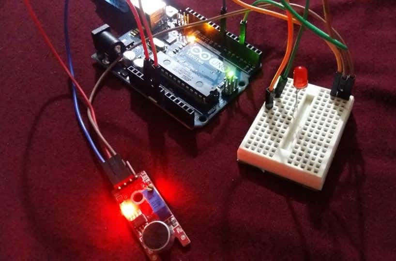
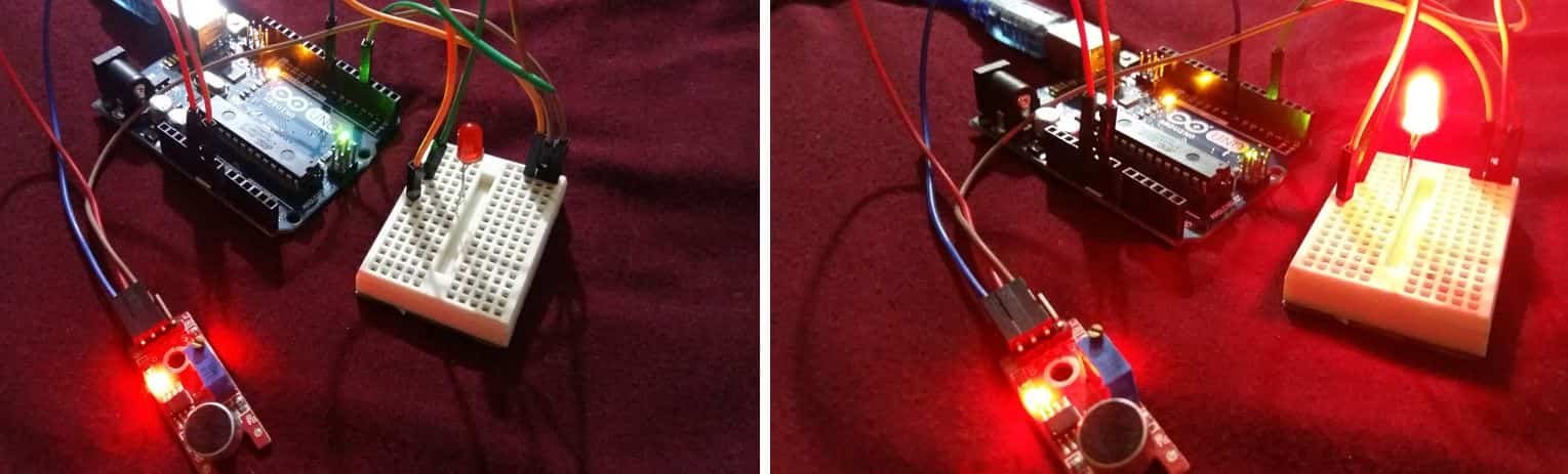
Now clap your hands close to the microphone of the sound sensor. Immediately, the LED will turn ON. It will remain ON until the next clap sound is heard. Then it will turn OFF.
You may like to read our other posts on different sensors interfacing with Arduino:
- MAX6675 K-Type Thermocouple with Arduino
- Interface L298N DC Motor Driver Module with Arduino
- TCS230/TCS3200 Color Sensor with Arduino
- Rotary Encoder Module with Arduino
- HC-SR04 Ultrasonic Sensor Interfacing with Arduino
- DHT11 DHT22 with Arduino – Display Readings on OLED
- Interface NEO-6M GPS Module with Arduino
There is an error in the code. Change the test in loop line as follows :
if (output == HIGH) {
And it works perfectly !